Sign In
Upload
Manuals
Brands
MEN Manuals
Touch Panel
DC19
User Manuals: MEN DC19 Rugged Panel PC
Manuals and User Guides for MEN DC19 Rugged Panel PC. We have
1
MEN DC19 Rugged Panel PC manual available for free PDF download: User Manual
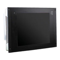
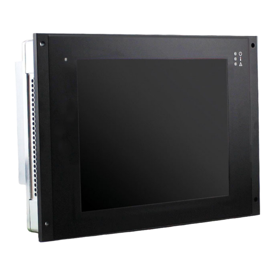
MEN DC19 User Manual (89 pages)
Rugged 10.4" Panel PC with Touch Screen, Rugged EN50155 Train Display Computer
Brand:
MEN
| Category:
Touch Panel
| Size: 3 MB
Table of Contents
Table of Contents
2
Contents
2
About this Document
6
Product Safety
8
Product Compliance
9
Disclaimer
10
Contacts
11
Product Overview
12
Product Description
12
Product Architecture
13
Interfaces
13
Figure 1. Front Interfaces
13
Figure 2. Rear Interfaces
14
Functions
15
Figure 3. Functional Diagram
15
Technical Data
16
Cooling Concept
19
Product Identification
20
Figure 4. Product Label
20
Getting Started
21
Unpacking the DC19
21
Configuring the Hardware
22
Installing a Micro-SIM Card
22
Mounting the DC19
24
Safety Instructions for Mounting
24
Panel Mounting
25
Figure 5. Dimensions and Mounting Hole Positions for Installation Site
25
Connecting and Starting
26
Safety Instructions for Connection
26
Connecting an Earthing Cable
26
Connecting Peripherals
27
Connecting the Power Supply
28
Starting up the System
28
Installing Operating System Software
28
MDIS System Package
28
Figure 6. Power Configuration and Coding Labeling
28
Using the DC19 under Linux
29
Linux Support for Individual Functions
29
Configuring Display Backlight/Button Light and LED Settings
30
LED States
31
Accessing Smbus/I2C Devices Using Duagon Tools
32
Accessing Smbus/I2C Devices Using Standard Linux I2C Tools
34
Managing RTC Time Adjustments
34
Enabling the Alarm Buzzer
35
Switching between RS232 and RS422/RS485 Interface
36
Using the DC19 under Windows
37
Windows Support for Individual Functions
37
Configuring Display Backlight/Button Light and LED Settings
38
LED States
39
Accessing Smbus/I2C Devices
40
Managing RTC Time Adjustments
41
Switching the Alarm Buzzer
41
Switching between RS232 and RS422/RS485 Interface
42
Functional Description
43
Power Supply
43
Display
43
Light Sensor
43
Table 3. Connector Types - Power Supply (4-Pin M12)
43
Table 4. Pin Assignment - Power Supply (4-Pin M12)
43
Table 5. Signal Mnemonics - Power Supply
43
Cpu
44
Processor Core
44
Trusted Platform Module (TPM)
44
Supervision and Management
44
Watchdog
44
Temperature Measurement
44
Front-Panel Leds
45
Alarm Buzzer
45
Table 6. Front-Panel Leds
45
Real-Time Clock (RTC)
46
Memory
47
System RAM
47
Mass Storage
47
Emmc
47
Isolation Voltages
48
Table 7. Isolation Voltages
48
Audio
49
Table 8. Connector Types - Audio M12 A-Coded
49
Table 9. Pin Assignment - Audio (8-Pin M12)
49
Table 10. Signal Mnemonics - Audio
49
Usb
50
Rear Connection
50
Table 11. Connector Types - 5-Pin M12 A-Coded
50
Table 12. Pin Assignment - USB (5-Pin M12)
50
Table 13. Signal Mnemonics - USB 1.X/2.0
50
Ethernet
51
Rear Connection
51
Signal Mnemonics
51
Table 14. Connector Types - Ethernet (8-Pin M12 X-Coded)
51
Table 15. Pin Assignment - Ethernet (8-Pin M12 X-Coded)
51
Table 16. Ethernet Cable Requirements
51
Table 17. Signal Mnemonics - Ethernet
51
Wireless Functionality
52
PCI Express Mini Card
52
Table 18. Pin Assignment - PCI Express Mini Card (Pcie and USB 2.0)
52
GNSS (Optional)
53
Table 19. Signal Mnemonics - PCI Express Mini Card
53
LTE (Optional)
54
WLAN (Optional)
54
Antenna Connectors (Optional)
54
SIM Card Interface
55
Figure 7. Switchable Micro-SIM Slots Default Allocation
55
Figure 8. SIM Card Switching Option
56
Multifunction Vehicle Bus (MVB) (Optional)
57
Digital I/O
57
Table 20. Connector Types - 5-Pin M12 B-Coded
57
Table 21. Pin Assignment - Digital I/O (5-Pin M12 B-Coded)
57
Table 22. Signal Mnemonics - Digital I/O
57
Rs232/Rs485/Rs422
58
Table 23. Connector Types - RS232/RS422/RS485 (5-Pin M12)
58
Table 24. Pin Assignment - RS232/RS422/RS485 (5-Pin M12)
58
Table 25. Signal Mnemonics - RS232
58
Table 26. Signal Mnemonics - RS422/RS485
58
CAN Bus
59
CAN Bus Termination
59
Table 27. Connector Types - 5-Pin M12 A-Coded
59
Table 28. Pin Assignment - CAN Bus (5-Pin M12)
59
Table 29. Signal Mnemonics - CAN Bus
59
Starter Kit
60
Power Cable
60
Table 30. Connector Types - 4-Pin M12 A-Coded
60
Table 31. Pin Assignment - Power (4-Pin M12)
60
Ethernet Cable
61
Table 32. Connector Types - Ethernet RJ45
61
Table 33. Pin Assignment - Ethernet (RJ45)
61
Table 34. Signal Mnemonics - Ethernet
61
USB Type a Cable
62
Table 35. Connector Types - USB 2.0
62
Table 36. Pin Assignment - USB 2.0
62
Table 37. Signal Mnemonics - USB 1.X/2.0
62
CAN D-Sub Cable
63
Table 38. Connector Types - 9-Pin CAN Bus D-Sub
63
Table 39. Pin Assignment - CAN Bus
63
RS232/RS422/RS485 D-Sub Cable
64
Audio D-Sub Cable
64
Digital I/O D-Sub Cable
66
Hardware/Software Interface
67
Smbus/I2C Devices
67
Digital I/O, Serial Interface, Alarm Buzzer SMB Register (0X40)
68
Wireless Function and Power Watchdog SMB Register (0X42)
68
BMC API (Application Programming Interface)
70
Command Packets
70
Maintenance
89
Cleaning the Display
89
Advertisement
Advertisement
Related Products
MEN Categories
Computer Hardware
Network Router
Switch
PCI Card
Industrial PC
More MEN Manuals
Login
Sign In
OR
Sign in with Facebook
Sign in with Google
Upload manual
Upload from disk
Upload from URL