
Summary of Contents for MEN DC19
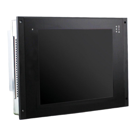
- Page 1 20DC19-00 E1 2020-10-27 DC19 Rugged 10.4" Panel PC with Touch Screen Rugged EN50155 Train Display Computer User Manual...
-
Page 2: Table Of Contents
Using the DC19 under Windows........ - Page 3 Contents 3 Functional Description......... . 43 Power Supply.
- Page 4 Contents 5 Maintenance ..........89 Cleaning the Display .
- Page 5 Contents Table 40. Signal mnemonics – CAN bus........63 Table 41.
-
Page 6: About This Document
About this Document About this Document This document is intended only for system developers and integrators. It describes the design, functions and connection of the product. The manual does not include detailed information on individual components (data sheets etc.). History Issue Comments Date... - Page 7 About this Document Conventions Indicates important information or warnings concerning situations which could result in personal injury, or damage or destruction of the component. Indicates important information concerning electrostatic discharge which could result in damage or destruction of the component. Indicates important information or warnings concerning proper functionality of the product described in this document.
-
Page 8: Product Safety
Product Safety Product Safety Read the user manual carefully before using the product. Keep the user manual for later reference. Conditions for Use, Field of Application The product is designed to function correctly in the market, application area and environmental conditions specified in the applicable standards which are listed in the Technical Data. -
Page 9: Product Compliance
Product Compliance Product Compliance duagon products are tested according to the standards given in the Technical Data and thus enable you to achieve certification of the product according to the standards applicable in your field of application. If the product delivered was certified by duagon and is modified by the customer, e.g., by installing an additional hardware component, the certification achieved by duagon becomes invalid and may have to be repeated for the new product configuration. -
Page 10: Disclaimer
Disclaimer Disclaimer Changes duagon Germany GmbH ("duagon") reserves the right to make changes without further notice to any products herein. Liability duagon makes no warranty, representation or guarantee of any kind regarding the suitability of its products for any particular purpose, nor does duagon assume any liability arising out of the application or use of any product or circuit, and specifically disclaims any and all liability, including, without limitation, consequential or incidental damages. -
Page 11: Contacts
Phone +33 450 955 312 sales-deu@duagon.com sales-fra@duagon.com www.duagon.com www.duagon.com China MEN Micro Inc. MEN Mikro Elektronik (Shanghai) Co., Ltd. 860 Penllyn Blue Bell Pike Jinjiang Xiangyang Tower Blue Bell, PA 19422 200040 Shanghai Phone +1 215 542 9575 Phone +86 159 0077 2985 sales-usa@duagon.com... -
Page 12: Product Overview
CCTV. Powerful & Energy-Efficient Computing The DC19 is powered by an Intel Atom processor from the E3900 series running at up to 1.6 GHz and equipped with up to 8 GB RAM with ECC and a 32 GB soldered eMMC. -
Page 13: Product Architecture
Product Overview Product Architecture 1.2.1 Interfaces Figure 1. Front interfaces Power LED Light sensor Temperature LED Warning LED 20DC19-00 E1 2020-10-27 ... -
Page 14: Figure 2. Rear Interfaces
Product Overview Figure 2. Rear interfaces Antenna Audio Ethernet 2 Earthing Stud cut-outs micro-SIM D-Sub cut-outs Digital I/O RS232/ Ethernet 1 Power Supply slots (dual SIM) for MVB RS422/ Connector RS485 20DC19-00 E1 2020-10-27 ... -
Page 15: Functions
Product Overview 1.2.2 Functions Figure 3. Functional diagram Power Supply DDR3 Gigabit Ethernet SDRAM Gigabit Ethernet USB 2.0 Power LED RS232/RS422/RS485 Temperature LED Warning LED Digital I/O eMMC 32 GB Intel Atom Processor Audio in/out E3900 Series Up to 2 antennas PCIe Mini Card Slot A 2 micro-SIM... -
Page 16: Technical Data
Product Overview Technical Data The following CPU types are supported: Intel Atom x5-E3930, 2 cores, 2 threads, 1.3 GHz, 1.8 GHz Turbo Boost, 6.5 W, 2 MB cache Intel Atom x5-E3940, 4 cores, 4 threads, 1.6 GHz, 1.8 GHz Turbo Boost, 9.5 W, 2 MB cache Intel Atom x7-E3950, 4 cores, 4 threads, 1.6 GHz, 2.0 GHz Turbo Boost, 12 W, 2 MB cache... - Page 17 Product Overview Audio 1x M12, A-coded, receptacle Stereo line input, single-ended Stereo line output, differential 1x USB 2.0, M12, A-coded, receptacle Ethernet 2x 10/100/1000BASE-T, M12, X-coded, receptacle PCI Express Mini Card 2x PCI Express Mini Card slot PCIe Full-Mini;...
- Page 18 (W) 310 mm, (D) 214 mm, (H) 75 mm Cutout: (W) 280 mm, (H) 205 mm See the duagon website for technical product drawings including the exact dimensions of DC19: www.duagon.com/products/dc19/#doc Weight: 4.5 kg Cooling: Air cooling, natural convection, airflow 0.4 m/s ...
-
Page 19: Cooling Concept
Application Note Recommendations for a Robust Software Setup Cooling Concept The DC19 is cooled by natural convection for fanless operation. Leave the following minimum space to those sides of the system that are needed for cooling to enable the required airflow: 15 cm ... -
Page 20: Product Identification
Product Identification The documentation may describe several different models and design revisions of the DC19. You can find the article number, design revision and serial number on either the product label or the system label. Article number: Indicates the product family and model. This is also the main ... -
Page 21: Getting Started
Getting Started Getting Started Unpacking the DC19 After unpacking, check whether there are any transport or other damages on the system. If one of the following situations arises, have the equipment checked by service personnel: The power cable or plug is damaged. -
Page 22: Configuring The Hardware
2.2.1 Installing a micro-SIM Card The dual micro-SIM card slot is located at the back of the DC19 housing and is protected by a metal cover. Figure 2, Rear interfaces on page 14 for the position of the micro-SIM card slot. - Page 23 Getting Started Insert the micro-SIM card into the card slot. Connected to M.2 card Connected to PCIe Mini Card 20DC19-00 E1 2020-10-27 ...
-
Page 24: Mounting The Dc19
Getting Started Mounting the DC19 2.3.1 Safety Instructions for Mounting Risk of Damages or Injuries Make sure that the supporting structure, e.g., cabinet or wall, where you want to install the system supports the weight of the system. Risk of Fire Through Overheating Make sure that the equipment does not overheat. -
Page 25: Panel Mounting
2.3.2 Panel Mounting The DC19 has been designed to either sit on a flat surface or be securely mounted in a cabinet, case or installed in the drivers desk in the driver’s cabin of a train. When mounting the DC19, first ensure that the surface has been prepared and that the cut-out area meets the required dimensions for the back part of the housing. -
Page 26: Connecting And Starting
Connecting and Starting 2.4.1 Safety Instructions for Connection Adhere to the following safety instructions before you connect the DC19: Works on the computer system may only be carried out by personnel qualified for the specific task, who, based on their training and experience, are able to identify risks and avoid potential hazards when working with these products/systems. -
Page 27: Connecting Peripherals
Connect an externally powered USB hub and connect a USB keyboard and mouse to it. » Connect all peripheral devices needed for your system function. See the duagon website for ordering information on the DC19 starter kit including all necessary cables: www.duagon.com/products/dc19/#ord Chapter 3.20 Starter Kit on page 60 for a detailed description of the starter kit. -
Page 28: Connecting The Power Supply
MDIS System Package The DC19 is supported by the MDIS framework. MDIS stands for MEN Driver Interface System and is a framework for device drivers for almost any kind of I/O hardware. It greatly simplifies system configuration, also in combination with specialized board BSPs. -
Page 29: Using The Dc19 Under Linux
Getting Started Using the DC19 under Linux 2.6.1 Linux Support for Individual Functions Notes: Functions have been tested with the mentioned software. Functions may be optional. 2.6.1.1 Board Management Controller (BMC) BMC device on SMBus Supported by: Standard Linux I2C tools Supported by: 13MD05-90 MDIS system package 2.6.1.2... -
Page 30: Configuring Display Backlight/Button Light And Led Settings
Supported by: duagon 13Y040-90 tool 2.6.2 Configuring Display Backlight/Button Light and LED Settings duagon provides a software tool for configuring the DC19 functionality. See the duagon website for the 13Y040-90 tool: www.duagon.com/software/13y040-90/ Carry out the following steps to install and use the tool: »... -
Page 31: Led States
Getting Started A list of the possible commands appears: ./13y040-90 Usage: 13Y040-90 <options> Print Usage Get device Info Toggle Display Enable increase display backlight intensity by 1% decrease display backlight intensity by 1% toggle touch enable -r10 increase display backlight intensity by 10% -d10 decrease display backlight intensity by 10% increase button light intensity... -
Page 32: Accessing Smbus/I2C Devices Using Duagon Tools
2.6.3 Accessing SMBus/I2C Devices using duagon Tools duagon provides a number of MDIS software tools for accessing DC19 functions via the SMBus, which are included in the MDIS5 System Package for Linux,13MD05-90: xm01bc_ctrl provides access to the board management controller (BMC) ... - Page 33 Getting Started » Print a list of all possible parameters of the xm01bc_ctrl tool sudo xm01bc_ctrl <device name> <device name> is a place holder for the name of the device Usage: xm01bc_ctrl [<opts>] <device> [<opts>] Function: Control XM01BC PIC Options: device device name show voltage values...
-
Page 34: Accessing Smbus/I2C Devices Using Standard Linux I2C Tools
Accessing SMBus/I2C Devices using Standard Linux I2C Tools duagon provides an application note with detailed information: See the duagon website: Using the Standard I2C Tools on MEN CPUs under Linux More information on supported functions and hardware implementation Chapter SMBus/I2C Devices ... -
Page 35: Enabling The Alarm Buzzer
Getting Started 2.6.6 Enabling the Alarm Buzzer There are two ways to enable the alarm buzzer: Using duagon software tools for Linux. Using standard Linux I2C tools 2.6.6.1 duagon Tools The alarm buzzer can be enabled and disabled via register 0x40 on the SMBus. This is done using the smb2_ctrl tool included in the MDIS5 System Package for Linux, 13MD05- To enable the alarm buzzer, e.g.: ... -
Page 36: Switching Between Rs232 And Rs422/Rs485 Interface
Getting Started 2.6.7 Switching between RS232 and RS422/RS485 Interface By default, the serial interface of the DC19 is set to RS422/RS485. The interface can be switched to RS232 in two ways: Using duagon software tools for Linux. Using standard Linux I2C tools ... -
Page 37: Using The Dc19 Under Windows
Getting Started Using the DC19 under Windows 2.7.1 Windows Support for Individual Functions Notes: Functions have been tested with the mentioned software. Functions may be optional. 2.7.1.1 Unsupported Functions The following functions are not supported: duagon D017M PCI Express Mini Card CAN bus ... -
Page 38: Configuring Display Backlight/Button Light And Led Settings
Supported by: duagon 13Y040-70 tool 2.7.2 Configuring Display Backlight/Button Light and LED Settings duagon provides a software tool for configuring the DC19 functionality. See the duagon website for the 13Y040-70 tool: www.duagon.com/software/13y040-70/ Carry out the following steps to install and use the tool: »... -
Page 39: Led States
Getting Started A list of the possible commands appears: > ./13y040-70 Usage: 13Y040-70 <options> Print Usage Get device Info Toggle Display Enable increase display backlight intensity by 1% decrease display backlight intensity by 1% toggle touch enable -r10 increase display backlight intensity by 10% -d10 decrease display backlight intensity by 10% increase button light intensity... -
Page 40: Accessing Smbus/I2C Devices
Getting Started 2.7.3 Accessing SMBus/I2C Devices duagon provides the Windows ERTC/SMB Support Package (13Y021-70) for accessing SMBus/I2C devices, e.g., board management functions. » Install the Windows ERTC/SMB Support Package 13Y021-70. See the duagon website for detailed information and documentation for 13Y021-70: www.duagon.com/products/software/13y021-70/ All necessary drivers are installed automatically. -
Page 41: Managing Rtc Time Adjustments
Getting Started Access the board information EEPROM (SMB address 0xAC) to read byte at offset 8: > smb2_ctrl smb2_1 rbd -a=0xac -o=0x8 Access the CPU board BMC (in this example at SMB address 0x9C) to read out the operating hours counter: >... -
Page 42: Switching Between Rs232 And Rs422/Rs485 Interface
2.7.6 Switching between RS232 and RS422/RS485 Interface By default, the serial interface of the DC19 is set to RS422/RS485. The interface can be switched to RS232 via register 0x40 on the SMBus. This is done using the Windows ERTC/ SMB Support Package (13Y021-70). The tool required for this is called smb2_ctrl. -
Page 43: Functional Description
Functional Description Functional Description Power Supply The DC19 is supplied via a power inlet connector at the back panel. Table 3. Connector types – power supply (4-pin M12) Connector Type On DC19 4-pin M12 plug, A-coded e.g., PHOENIX SACC-CI-M12MS-4CON-L180 THR-... -
Page 44: Cpu
Trusted Platform Module (TPM) A trusted platform module for authenticating the hardware to ensure platform integrity is available on the DC19. The TPM module is compliant to the TPM specification. Supervision and Management The DC19 provides an intelligent board management controller (BMC) with the following... -
Page 45: Front-Panel Leds
Linux. Alarm Buzzer The DC19 features a buzzer for signaling an alarm. The buzzer is connected to a frequency generator. It is enabled via an SMBus signal and has an SPL of 70 dB +/-3 dB in free air at a distance of 1 m. -
Page 46: Real-Time Clock (Rtc)
Functional Description Real-Time Clock (RTC) The DC19 includes a real-time clock connected to the processor as the system RTC (ERTC) RX-8571. The RTC has an accuracy of approximately 1.7 seconds/day (11 minutes/year) at 25°C. The real-time clock device is connected to the CPU via SMBus. -
Page 47: Memory
Functional Description Memory 3.9.1 System RAM The DRAM system memory of DC19 is scalable. Chapter 1.3 Technical Data on page See the duagon website for available standard configurations: www.duagon.com/products/dc19/#ord 3.10 Mass Storage 3.10.1 eMMC The DC19 has a pre-installed eMMC multimedia device. -
Page 48: Isolation Voltages
Functional Description 3.11 Isolation Voltages Isolation voltage groups: 1 = Power 2 = GND / Shield, USB, DisplayPort, Audio 3 = ETH_1 4 = ETH_2 5 = RS232/RS422/485 6 = CAN 7 = DIG_IN1..2, ISO_REF_GND, OPT1, OPT2 ... -
Page 49: Audio
Functional Description 3.12 Audio Table 8. Connector types – Audio M12 A-coded Connector Type On DC19 8-pin M12 straight receptacle, A-coded (SACC-CI-M12FS-8CON-L180-THR - 1557808) Mating 8-pin M12 plug, A-coded (Phoenix Contact SACC-M12MS-8Q SH - 1543236 (straight)) Table 9. Pin assignment – Audio (8-pin M12) -
Page 50: Usb
3.13.1 Rear Connection Table 11. Connector types – 5-pin M12 A-coded Connector Type On DC19 5-pin M12 straight receptacle A-coded, e.g., Phoenix Contact SACC-CI- M12FS-5CON-L180-THR SH - 1432363 Mating 5-pin M12 plug A-coded Table 12. Pin assignment – USB (5-pin M12) -
Page 51: Ethernet
3.14.1 Rear Connection Table 14. Connector types – Ethernet (8-pin M12 X-coded) Connector Type On DC19 8-pin M12 receptacle, X-coded e.g., Phoenix Contact SACC-CI-M12FS-8CON-L180-10G - 1402457 Mating 8-pin M12 plug, X-coded e.g., Phoenix Contact VS-08-M12MS-10G-P SCO - 1417430 (straight) e.g., Phoenix Contact VS-08-M12MR-10G-P SCO - 1417443 (angled) Table 15. -
Page 52: Wireless Functionality
Functional Description 3.15 Wireless Functionality 3.15.1 PCI Express Mini Card The DC19 supports: Full-size cards according to the PCI Express Mini Card Standard. USB 2.0 PCI Express x1 The PCIe Mini Card must be implemented together with antenna cables. -
Page 53: Gnss (Optional)
Wake signal SMB_CLK System management bus clock SMB_DATA System management bus data USB 2.0 USB_D+/- USB lines 3.15.2 GNSS (Optional) The DC19 offers cutouts prepared for GNSS. See the duagon website for available GNSS modules: www.duagon.com/products/dc19/#ord 20DC19-00 E1 2020-10-27 ... -
Page 54: Lte (Optional)
The DC19 offers cutouts prepared for WLAN. See the duagon website for available WLAN modules: www.duagon.com/products/dc19/#ord 3.15.5 Antenna Connectors (Optional) By default, the DC19 is equipped with two antenna cutouts at the rear panel. The DC19 supports: RP-SMA ... -
Page 55: Sim Card Interface
3.15.6 SIM Card Interface The DC19 is equipped with an externally accessible dual micro-SIM card holder. To get access to a mobile phone network you need a SIM card (subscriber identity module) and a contract with a mobile service provider. -
Page 56: Figure 8. Sim Card Switching Option
Functional Description Figure 8. SIM card switching option SIM1 PCIe Mini Card SIM2 PCIe Mini Card SIM1 PCIe Mini Card SIM2 PCIe Mini Card 20DC19-00 E1 2020-10-27 ... -
Page 57: Multifunction Vehicle Bus (Mvb) (Optional)
3.16 Multifunction Vehicle Bus (MVB) (Optional) The DC19 can be ordered with an MVB interface with physical layers ESD + (Electrical Short Distance) or EMD (Electrical Middle Distance), according to IEC 61375 (TCN standard). MVB can be added using a PCI Express Mini Card and features: Cyclic transmission of process data (PD) (broadcast) ... -
Page 58: Rs232/Rs485/Rs422
Chapter 4.1.1 Digital I/O, Serial Interface, Alarm Buzzer SMB Register (0x40) on for more information on the SMBus configuration registers. page 68 The DC19 does not have an internal BIAS network for terminating the RS485/RS422 interface. Table 23. Connector types – RS232/RS422/RS485 (5-pin M12) -
Page 59: Can Bus
3.19 CAN Bus Table 27. Connector types – 5-pin M12 A-coded Connector Type On DC19 5-pin M12 straight receptacle A-coded, e.g., Phoenix Contact SACC-CI- M12FS-5CON-L180-THR SH - 1432363 Mating 5-pin M12 plug A-coded Table 28. Pin assignment – CAN bus (5-pin M12) -
Page 60: Starter Kit
Functional Description 3.20 Starter Kit See the duagon website for ordering information on the DC19 starter kit including all necessary cables: www.duagon.com/products/dc19/#ord The starter kit 05DC19-00 includes the following components: 1x AC/DC power supply to power 4-pin M12 cable ... -
Page 61: Ethernet Cable
Functional Description 3.20.2 Ethernet Cable Table 32. Connector types – Ethernet RJ45 Connector Type On cable Modular 8/8-pin receptacle according to FCC68 Mating Modular 8/8-pin plug according to FCC68 Table 33. Pin assignment – Ethernet (RJ45) 10GBASE-T/ 1000BASE-T BI_DA+ BI_DA- BI_DB+ BI_DC+ BI_DC-... -
Page 62: Usb Type A Cable
Functional Description 3.20.3 USB Type A Cable Table 35. Connector types – USB 2.0 Connector Type On cable 4-pin USB Type A receptacle according to Universal Serial Bus Specification Revision 1.0 Mating 4-pin USB Type A plug according to Universal Serial Bus Specification Revision 1.0 Table 36. -
Page 63: Can D-Sub Cable
Functional Description 3.20.4 CAN D-Sub Cable Table 38. Connector types – 9-pin CAN bus D-Sub Connector Type On cable 9-pin CAN bus D-Sub receptacle Mating 9-pin CAN bus D-Sub plug Table 39. Pin assignment – CAN bus CAN_L CAN_TERM CAN_GND CAN_TERM CAN_H Table 40. -
Page 64: Rs232/Rs422/Rs485 D-Sub Cable
Functional Description 3.20.5 RS232/RS422/RS485 D-Sub Cable Table 41. Connector types – 9-pin D-Sub plug Connector Type On cable 9-pin D-Sub plug Mating 9-pin D-Sub receptacle Table 42. Pin assignment – RS232/RS422/RS485 (9-pin D-Sub) RS232 RS422 RS485 RS232 RS422 RS485 TX/RX- TX/RX+ Table 43. - Page 65 Functional Description Table 47. Signal mnemonics – Audio Signal Direction Function AUDIO_GND Audio ground AUDIO_IN_+/- Single ended stereo audio input AUDIO_OUT_L_+/- Audio out, left channel AUDIO_OUT_R_+/- Audio out, right channel 20DC19-00 E1 2020-10-27 ...
-
Page 66: Digital I/O D-Sub Cable
Functional Description 3.20.7 Digital I/O D-Sub Cable Table 48. Connector types – 9-pin D-Sub Connector Type On cable 9-pin D-Sub receptacle Mating 9-pin D-Sub plug Table 49. Pin assignment – Digital I/O (9-pin D-Sub) I-GND DIG_OUT_2 DIG_OUT_1 DIG_IN_2 DIG_IN_1 Table 50. Signal mnemonics –... -
Page 67: Hardware/Software Interface
Hardware/Software Interface Hardware/Software Interface This chapter is intended for software developers or system integrators who need deeper knowledge of the implementation details of the product’s interfaces and its internal connections. SMBus/I2C Devices Table 51. SMBus/I2C devices 8-Bit Address 7-Bit Address Function Board Management Controller (BMC) 0x9A... -
Page 68: Digital I/O, Serial Interface, Alarm Buzzer Smb Register (0X40)
Hardware/Software Interface 4.1.1 Digital I/O, Serial Interface, Alarm Buzzer SMB Register (0x40) Table 52. Digital I/O, Serial Interface, Alarm Buzzer SMB Register (0x40) UART_ Name BUZ_EN GPO1 GPO0 GPI1 GPI0 CONFIG Reset Bit Field Description BUZ_EN Enable or disable audio alarm buzzer at front panel 0: Enable alarm buzzer ... - Page 69 Hardware/Software Interface Bit Field Description CARD_B_PWR_EN Control power to the wireless interface card B 0: Disable power supply to wireless interface card 1: Enable power supply to wireless interface card WDOG_EN Reset the power supply watchdog (ignition) 0: Reset the power supply watchdog (ignition) ...
-
Page 70: Bmc Api (Application Programming Interface)
Hardware/Software Interface BMC API (Application Programming Interface) The DC19 uses a generic command interface for communication between the host (CPU) and the controller (BMC). Application software uses command packets to communicate with the BMC. The application software controls the BMC via I2C/SMBus. The device address is 0x4D (in 7-bit, non-shifted notation) or 0x9A/0x9B (in 8-bit, shifted notation, write/read). - Page 71 Hardware/Software Interface The packet types are directly mapped to the corresponding SMBus “bus protocols” as defined in the System Management Bus Specification. Table 56. API – Packet types mapping on SMBus Packet Type SMBus Protocol PT_SB Send byte PT_RBD Read byte PT_WBD Write byte PT_RWD...
- Page 72 Hardware/Software Interface Commands WDOG_TIME_SET and WDOG_TIME_GET Command WDOG_TIME_SET Opcode: 0x14 Packet Type: PT_WWD Data 0 WD_TOUT (LSB) Data 1 WD_TOUT (MSB) Command WDOG_TIME_GET Opcode: 0x14 Packet Type: PT_RWD Data 0 WD_TOUT (LSB) Data 1 WD_TOUT (MSB) Bit Field Description WD_TOUT Trigger timeout, in steps of 100 ms 0x0001: 100 ms ...
- Page 73 4.2.1.3 Power Resume Mode Commands These commands allow configuring the behavior of the DC19 in case the power is reapplied after a power failure and input voltages return to their allowed limits. The setting is persistent, i.e. it is stored in non-volatile memory.
- Page 74 Hardware/Software Interface Command RESUME_MODE_SET Opcode: 0x20 Packet Type: PT_WBD Data RES_MODE Command RESUME_MODE_GET Opcode: 0x20 Packet Type: PT_RBD Data RES_MODE Bit Field Description RES_MODE Resume mode 0x00: Off 0x01: On 0x02: Former 20DC19-00 E1 2020-10-27 ...
- Page 75 4.2.1.4 Reset Signal Blocking These commands allow blocking of DC19 reset inputs. The setting is persistent, i.e. it is stored in non-volatile memory. In a system with master and slave CPU boards, normally the slave boards will get a reset whenever the master board resets.
- Page 76 Hardware/Software Interface 4.2.1.5 Software Reset These commands allow performing CPU resets under application software control. Different types of resets are available: SW_RESET issues a “warm reset”. SW_COLD_RESET issues a “cold reset”. SW_RTC_RESET issues a “cold reset”, together with an RTC reset. ...
- Page 77 Hardware/Software Interface 4.2.1.6 Voltage Supervision The voltage supervision commands allow the customer application to monitor different voltages on the DC19. Table 62. BMC API – Voltage supervision commands Command Packet Type Opcode Functional Description VOLT_LOW(0) PT_RWD Get lower limit of +3.3 V (in mV)
- Page 78 Hardware/Software Interface Command VOLT_ACT(x) Opcode: 0x60 + x Packet Type: PT_RWD Data 0 Actual value of voltage x (LSB) Data 1 Actual value of voltage x (MSB) Command NUM_VOLTS Opcode: 0x8E Packet Type: PT_RBD Data Number of supervised voltages 20DC19-00 E1 2020-10-27 ...
- Page 79 Hardware/Software Interface 4.2.1.7 Error Counters The error counter commands allow querying and clearing error counters. The BMC provides error counters for each type of error that can occur. Using this information, the application software can determine how often certain errors have occurred, but it is not possible to determine the chronological order of the errors.
- Page 80 Hardware/Software Interface Command ERRCNT_xx (16 to 32) Opcode: 0xB0 + x Packet Type: PT_RBD Data Value of error counter number xx Command ERR_CNT_CLR This command clears all error counters. Opcode: 0x7F Packet Type: PT_WBD Data 0x69 Command NUM_ERR_CNTRS Opcode: 0x8D Packet Type: PT_RBD Data Number of error counters...
- Page 81 Hardware/Software Interface 4.2.1.8 Firmware Revision The firmware revision commands allow querying the separate parts of the BMC firmware revision. Table 65. BMC API – Firmware version commands Command Packet Type Opcode Functional Description GETREV_WORD0 PT_RWD Get firmware revision major part 0x80 GETREV_WORD1 PT_RWD...
- Page 82 4.2.1.9 Hardware Board Type This command allows the BMC to query the board type, i.e. a unique ID that MEN assigns to each hardware board the generic BMC is implemented on. The board type is programmed into the BMC during production. The setting is persistent, i.e. is stored in a non-volatile memory.
- Page 83 Hardware/Software Interface 4.2.1.10 Last Error This command allows querying the last error. Table 66. BMC API – Last error command Command Packet Type Opcode Functional Description ERR_LAST PT_RBD Get last error 0x90 Command ERR_LAST Opcode: 0x90 Packet Type: PT_RBD Data LAST_ERR_CODE Bit Field Description...
- Page 84 Hardware/Software Interface 4.2.1.11 Power Failure Flags This command allows querying the power failure flags of the DC19. Table 67. BMC API – Power failure flags command Command Packet Type Opcode Functional Description ERR_PWR_FLAGS PT_RBD Get power failure flags 0x91 Command ERR_PWR_FLAGS Whenever a power failure occurs, the respective flag is set to 1 until the Power Failure Flag Register is cleared.
- Page 85 Hardware/Software Interface 4.2.1.12 Reset Reason This command allows querying the reason of the last reset. The BMC maintains a Reset Reason Register that stores the reason for the last reset issued by the BMC. Table 68. BMC API – Reset reason command Command Packet Type Opcode...
- Page 86 Hardware/Software Interface 4.2.1.13 Clear Error Registers This command allows clearing the Reset Reason Register, Last Error Register and Power Failure Flag Register, collectively called ’error registers’. Table 69. BMC API – Clear error registers command Command Packet Type Opcode Functional Description ERR_REG_CLR PT_WBD Clear error registers...
- Page 87 Hardware/Software Interface 4.2.1.15 Operating Hours Counter This command allows querying the operating hours counter. The operating hours counter counts the number of hours and minutes the board has been (at least partly) powered on, i.e. when the system is in S3 or S0 state. S0 to S5 are the power states as defined in the ACPI specification, or an equivalent state.
- Page 88 Set LED state 0xA0 LED_CTRL_GET PT_RBD Get LED state 0xA0 Command LED_CTRL_SET Opcode: 0xA0 Packet Type: PT_WBD Data Command LED_CTRL_GET Opcode: 0xA0 Packet Type: PT_RBD Data Bit Field Description The DC19 BMC API supports no LEDs 20DC19-00 E1 2020-10-27 ...
-
Page 89: Maintenance
Maintenance Maintenance Cleaning the Display Clean the display of the DC19 with a moist, soft cloth. Do not use abrasive detergents in order to avoid damaging the laminated glass that protects the display. 20DC19-00 E1 2020-10-27 ...
Need help?
Do you have a question about the DC19 and is the answer not in the manual?
Questions and answers