Sign In
Upload
Manuals
Brands
MEASUREMENT TECHNOLOGY Manuals
Measuring Instruments
LCI-100
MEASUREMENT TECHNOLOGY LCI-100 Manuals
Manuals and User Guides for MEASUREMENT TECHNOLOGY LCI-100. We have
1
MEASUREMENT TECHNOLOGY LCI-100 manual available for free PDF download: Installation Manual
MEASUREMENT TECHNOLOGY LCI-100 Installation Manual (70 pages)
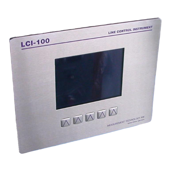
Line Control Instrument
Brand:
MEASUREMENT TECHNOLOGY
| Category:
Measuring Instruments
| Size: 0 MB
Table of Contents
Table of Contents
2
Overview
6
Figure 1.1 - LCI-100 Front Panel
6
Quick Start
7
Mounting
7
Basic Field Wiring
7
Figure 2.1 - Power Hookup - DC Power
7
Basic Hardware Configuration
8
Basic Operation
8
Figure 2.2 - Tension Hookup - 4 Wire 4-20 Ma Signal
8
Figure 2.3 - Payout Hookup - 2 Channel 12VDC Proximity Switch
8
Mechanical Installation
11
Environmental Considerations
11
Dimensions and Cutout
11
Display Mounting
11
Options and Wiring Diagrams
12
Figure 4.1 - Identification of Hardware Options and Manual Sections by Function
12
Wiring Hookup - Local Display
13
Display Power and Fuse
13
Tension Sensor Inputs
13
Figure 4.2 - Fuse Rating and Replacement Part - Local Display
13
Figure 4.3 - Local Display Power Hookup - DC Power
13
Figure 4.4 - Local Display Power Hookup - AC Power
13
Figure 4.5 - Tension Hookup - 3 Wire 4-20 Ma Signal
14
Figure 4.6 - Tension Hookup - 4 Wire 4-20 Ma Signal
14
Figure 4.7 - Tension Hookup - 2 Wire 4-20 Ma Signal
15
Figure 4.8 - Tension Hookup - 4 Wire DC Voltage Input
15
Figure 4.9 - Tension Hookup - 4 Wire Strain Gauge
15
Count Sensor Inputs
16
Figure 4.10 - Tension Hookup - Isolated 2 Wire 4-20 Ma Signal
16
Figure 4.11 - Payout Hookup - 12V NPN/PNP Switches - Primary
16
Figure 4.12 - Payout Hookup - 12V NPN/PNP Switches - Secondary
17
Figure 4.13 - Payout Hookup - TTL Encoder - Primary
17
Figure 4.14 - Payout Hookup - TTL Encoder - Secondary
17
Alarm Outputs
18
Shunt Calibration
18
Figure 4.15 - Alarm Output Hookup - 8 Channels
18
Figure 4.16 - Shunt Calibration Hookup
18
Analog Outputs
19
Figure 4.17 - Non- Isolated Analog Output Hookup
19
Figure 4.18 - Non- Isolated Analog Output Hookup
19
Serial Communications
20
Figure 4.19 - Isolated Analog Output Hookup - 4 Channels
20
Figure 4.20 - RS-485 Network Communcation Hookup
20
Wiring Hookup - LCI-90R Remote Display
21
LCI-90R Display Power and Fuse
21
Figure 4.21 - Remote Display Fuse Rating and Replacement Part
21
Figure 4.22 - Remote Display Power Hookup - DC Power
21
Figure 4.23 - Remote Display Power Hookup - AC Power
21
LCI-90R Communication Ports
22
Figure 4.24 - LCI-90R Auxiliary RS-232 Hookup
22
Figure 4.25 - LCI-90R Network RS-232 Hookup
22
Figure 4.26 - LCI-90R Network RS485 Hookup
22
LCI-90R Display Brightness Adjustment
23
Local Display Operation
24
Front Panel Identification
24
Figure 5.1 - LCI 100 Front Panel
24
Programming Menu
25
Alarms
26
Figure 5.2 - LCI 100 Menu Tree
26
Acknowledging Alarms
27
Setting Alarm Limits
27
Figure 5.3 - Sample Alarm Message Display
27
Configuring Alarms
28
Tension Calibration
29
Figure 5.4 - Digital Output Module Locations and Menu Names
29
Scale and Offset
30
Two Point Live Calibration
30
Look-Up Tables
31
Tension Tare
32
Shunt Calibration
33
Wrap Angle (Single-Input Configurations)
34
Wrap Angle Adjustments
34
Sensor Angle (Two-Axis Input Configurations)
35
Sensor Angle Correction for Dual-Axis Load Pins
35
Payout Calibration
36
Payout Scale
36
Payout Preset
36
Display Configuration
37
Locating Variables on Screen
37
Setting Display Units
38
Figure 5.5 - LCI-100 Display Units
38
Setting Decimal Places
39
Setting Bar Graph Range
39
Tension Display Smoothing
39
Screen Saver
39
Hardware Configuration
40
Security
40
Factory Setup
40
Analog Input Configuration
41
Using Multiple Tension Sensors
41
Sensor Input Check Alarm
42
Analog Output Channels
43
Calibrating the Analog Output Signal
43
Figure 6.1 - Analog Output Module Locations and Menu Names
43
Alarm Configuration
44
Alarm Types
45
Alarm Limits
45
Alarm Outputs
45
Serial Communication
45
Local/Remote Operation Modes
46
Programming Remote Displays
47
AUX Com Port Settings
47
Protocol Descriptions
48
Polling Strings
49
Remote Display Operation
50
Active Remotes - REM-A
50
Blind Remotes - REM-B
51
Troubleshooting
52
DIAG Screen Operation
52
Figure 8.1 - Diagnostics Screen Display
52
Troubleshooting Procedures
53
Technical Support
57
Appendix A - Dimensional Drawing
58
Appendix B - Jumper Settings on Interface PCB - REV 1
59
Appendix C - Analog Hardware Configuration
61
Appendix D - Interface PCB REV 1
63
Appendix E - Wrap Angle Calculations
64
Appendix F - Idealized Dual Axis Load Pin Geometry
65
Appendix G - Non Idealized Dual Axis Load Pin Geometry
66
Appendix H - LCI-100 Specifications
67
Appendix I - LCI-90R Specifications
70
Advertisement
Advertisement
Related Products
MEASUREMENT TECHNOLOGY LCI-90
MEASUREMENT TECHNOLOGY Categories
Measuring Instruments
More MEASUREMENT TECHNOLOGY Manuals
Login
Sign In
OR
Sign in with Facebook
Sign in with Google
Upload manual
Upload from disk
Upload from URL