Table of Contents
Advertisement
Quick Links
INSTALLATION MANUAL
LCI-100 Line Control Instrument
LCI-100
TENSION
0
SPEED
61.00
TENSION L
MENU
Measurement Technology NW
Revision 1.02.B
November 20, 2000
100000
110000
PAYOUT
FPM
23500
PAYOUT H
DIAG
ALRM CALB
Copyright 2000
th
4211 24
Ave West
Seattle WA 98199, USA
Phone: 206.634.1308
Fax: 206.634.1309
Email: LCI@mtnw-usa.com
LINE CONTROL INSTRUMENT
LBS
250000
FT
SPEED H
RSET
MEASUREMENT TECHNOLOGY NW
www.mtnw-usa.com
Advertisement
Table of Contents
Troubleshooting

Related Manuals for MEASUREMENT TECHNOLOGY LCI-100

Summary of Contents for MEASUREMENT TECHNOLOGY LCI-100
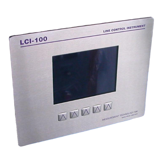
- Page 1 INSTALLATION MANUAL LCI-100 Line Control Instrument Revision 1.02.B November 20, 2000 LCI-100 LINE CONTROL INSTRUMENT TENSION 100000 110000 250000 SPEED PAYOUT 61.00 23500 TENSION L SPEED H PAYOUT H MENU DIAG ALRM CALB RSET MEASUREMENT TECHNOLOGY NW www.mtnw-usa.com Copyright 2000...
-
Page 2: Table Of Contents
Measurement Technology NW LCI-100 Operator Manual Page 2 Table of Contents Overview ......................... 6 Quick Start........................7 Mounting........................7 Basic Field Wiring ......................7 Basic Hardware Configuration..................8 Basic Operation......................8 Mechanical Installation....................11 Environmental Considerations ................... 11 Dimensions and Cutout ....................11 Display Mounting ....................... - Page 3 Measurement Technology NW LCI-100 Operator Manual Page 3 Sensor Angle (two-axis input configurations)............. 35 5.8.1 Sensor Angle Correction for Dual-Axis Load Pins................35 Payout Calibration ..................... 36 5.9.1 Payout Scale ..............................36 5.9.2 Payout Preset...................Error! Bookmark not defined. 5.10 Display Configuration ....................36 5.10.1...
- Page 4 Page 4 14.0 Appendix F – Idealized Dual Axis Load Pin Geometry ..........65 15.0 Appendix G – Non Idealized Dual Axis Load Pin Geometry........66 16.0 Appendix H – LCI-100 Specifications................. 67 17.0 Appendix I – LCI-90R Specifications ................. 70...
- Page 5 Figure 5.3 – Sample Alarm Message Display ................ 27 Figure 5.4 – Digital Output Module Locations and Menu Names ......... 29 Figure 5.5 – LCI-100 Display Units ..................38 Figure 6.1 – Analog Output Module Locations and Menu Names ......... 43...
-
Page 6: Overview
This manual is intended to cover the installation, set-up, and operation of the LCI-100 and the LCI-90R remote display. -
Page 7: Quick Start
LCI-100. For a complete technical description please refer to Sections 3.0-6.0. Mounting The LCI-100 will fit in a 9.25 x 7.00” cutout, with a minimum of 5.5” depth clearance (see Appendix A for dimensional drawing). The instrument is held in place with removable panel clamps that screw to all sides of the display. -
Page 8: Basic Hardware Configuration
Sections 4.0-6.0. Basic Operation The LCI-100 base unit is configured at the factory to display Tension at the top of the screen, both numerically and as an analog bar graph immediately underneath. Speed is displayed in the middle on the left and Payout on the right, as shown on the cover. - Page 9 Measurement Technology NW LCI-100 Operator Manual Page 9 To calibrate either the Tension or Payout sensors, just press the CALB button on the RUN screen. This will bring up the 2.0 CALIBRATE display. (Or press MENU to get the 0 MAIN MENU shown below, then select 2 CALIBRATION;...
- Page 10 Measurement Technology NW LCI-100 Operator Manual Page 10 To calibrate the Tension sensor, select menu item 1 TENSION (THREE METHODS) to move to the 2.1 TENSION CAL METHOD 1 menu shown below. Select Item 2 and enter the full-scale Tension sensor output in pounds. Then select Item 3 and enter the Tension offset in pounds.
-
Page 11: Mechanical Installation
5.5”. Environmental Considerations The front face of the LCI-100 is designed for NEMA 4X applications. It consists of a 316 stainless steel top layer, a sealed lexan window, and five membrane-sealed stainless steel push buttons. The rear cage is NEMA 1 and requires protection with a suitable enclosure. -
Page 12: Options And Wiring Diagrams
I/O modules installed. The wiring diagrams are given in this Section; the optional I/O modules are listed in Appendix D. The table below gives of a summary of the LCI-100 functions, referenced to their associated menu, required hardware options, and section of this manual covering the wiring termination. -
Page 13: Wiring Hookup - Local Display
216.500 LCI-100-AC 1/2 A Figure 4.2 – Fuse rating and replacement part – Local display The LCI-100-DC requires an 18-36 Volt DC power source. The connection for the power is shown below. POWER IN Power: 18-36 VDC, 0.625 A DC + V–... -
Page 14: Figure 4.5 - Tension Hookup - 3 Wire 4-20 Ma Signal
The factory configuration internally connects the auxiliary DC output COM to the CH (1-6) LO. The LCI-100 can accept input from dual axis load pins on any two adjacent channels. The first channel should be the x-axis input, the second channel should be the y-axis input. -
Page 15: Figure 4.7 - Tension Hookup - 2 Wire 4-20 Ma Signal
Measurement Technology NW LCI-100 Operator Manual Page 15 Direct Input – 4-20 mA, Two Wire, Channel 1 AUX DC OUT Force Xducer: 2 Wire, 4-20 mA 24 VDC EXCITATION ANALOG CH1 HI SIGNAL + Note: 24V COM internally connected to CH1LO. -
Page 16: Count Sensor Inputs
2.3 volts for high-low transitions. Each different sensor type requires a specific hardware jumper setting on the inter- face PCB (see Appendix B). The LCI-100 can accept two separate quadrature inputs. Below are the wiring diagrams for the different sensor types with typical excitation voltages. -
Page 17: Figure 4.12 - Payout Hookup - 12V Npn/Pnp Switches - Secondary
Measurement Technology NW LCI-100 Operator Manual Page 17 Dual NPN/PNP Switches, +12 V Excitation, Secondary Channel DIGITAL Payout Sensors – Proximity Switch EXCITATION – SENSOR A EXCITATION – SENSOR B SIGNAL – SENSOR A SIGNAL – SENSOR B COMMON – SENSOR A COMMON –... -
Page 18: Alarm Outputs
The LCI-100 provides a method for “shunt calibration” of a load cell or load pin. The sensor must have an internal relay that connects a precision resistor across one leg of the bridge. The LCI-100 uses the Opto 8 output module to energize this relay. Shunt Calibration Connections... -
Page 19: Analog Outputs
Page 19 4.1.6 Analog Outputs The LCI-100 provides two non-isolated analog outputs, or up to four isolated analog outputs using signal conditioning modules. In both cases these outputs can be 4-20 mA, 0-5 Vdc, or 0-10 Vdc. Each different output type requires a specific hardware jumper setting on the interface PCB (see Appendix B). -
Page 20: Serial Communications
Figure 4.19 – Isolated Analog Output Hookup – 4 Channels 4.1.7 Serial Communications The LCI-100 provides both RS-232 and RS-485 serial communication options with a maximum of two ports. The base model has no serial ports. A RS-232 network port can be added for data logging to a single remote device in close proximity. -
Page 21: Wiring Hookup - Lci-90R Remote Display
A LCI-90R remote can be used to independently display (and optionally echo) all the line variables measured by a LCI-100. The LCI-90R does not support field I/O and thus has a much reduced wiring and configuration specification compared to the LCI-100. This sec- tion describes the wiring and other options associated with the LCI-90R. -
Page 22: Lci-90R Communication Ports
4.2.2 LCI-90R communication ports The LCI-90R provides two serial communication ports on TB2, the network and the auxiliary ports. The connection to the LCI-100 is made via the network port, which is factory configured as either RS-232 (standard) or RS-485 (optional). The RS-232 configuration is suitable when the LCI-100 is connected to a single LCI-90R remote within 50 feet. -
Page 23: Lci-90R Display Brightness Adjustment
Measurement Technology NW LCI-100 Operator Manual Page 23 4.2.3 LCI-90R display brightness adjustment The display brightness on the LCI-90R HT model can be varied by using SW-2 on the rear panel to change the scan rate, or by adjusting the rotary potentiometer (also on the rear panel) marked DISP. -
Page 24: Local Display Operation
Local Display Operation Front Panel Identification The LCI-100 front panel, shown in Figure 5.1, features a high visibility display and a five- button keypad. Each key has a label at the bottom of the screen that identifies its function. When a key is pressed its function (and the label) changes to reflect the current “operating mode”... -
Page 25: Programming Menu
Page 25 Programming Menu The LCI-100 is user programmable via the front panel keypad and the display. Program- ming options include selection of input/output signal ranges, setting screen displays and formats, defining alarm points, and calibrating the unit. The menu tree is shown below in Figure 5.2. -
Page 26: Alarms
Figure 5.2 – LCI 100 Menu Tree Alarms The LCI-100 provides the user with up to six optional visual alarms that can be configured to indicate high and low conditions of Tension, Payout, and line Speed. Each alarm can be assigned to any of the three measured variables, and can be designated as a high or low alarm. -
Page 27: Acknowledging Alarms
This alarm configuration menu is covered in Section 5.3.3. In addition to these six high-level alarms, the LCI-100 can be configured to monitor each analog input channel, watching for a low-level fault condition. This is particularly useful with multiple input configurations, where the failure of a single sensor might not be easily noticed. -
Page 28: Configuring Alarms
Measurement Technology NW LCI-100 Operator Manual Page 28 1.0 SET ALARMS > 1 TENSION > 10000 TONS TENSION > 8000 TONS PAYOUT > 2500 FT PAYOUT < 100 FT SPEED > 250 FPM NONE CHANGE CONFIGURATION 5.3.3 Configuring Alarms To configure the alarm settings, go to menu 4.3 ALARM CONFIGURATION shown below by pressing the MENU key from the RUN screen and navigating through the menu (or by selecting Item 7 in the 1.0 SET ALARMS menu above) -
Page 29: Tension Calibration
Measurement Technology NW LCI-100 Operator Manual Page 29 Setting Hardware/Terminal Block OPTO Module 1 / OPTO 1 ± OPTO Module 2 / OPTO 2 ± OPTO Module 3 / OPTO 3 ± OPTO Module 4 / OPTO 4 ± Figure 5.4 – Digital Output Module Locations and Menu Names, 4 of 8 Channels Shown Item 4 Selects HIGH or LOW alarm conditions. -
Page 30: Scale And Offset
Measurement Technology NW LCI-100 Operator Manual Page 30 5.4.1 Scale and offset The Scale and Offset values displayed in Menu 2.1 are the actual numbers used in the calculation of displayed Tension (unless a lookup table is being used). The menu for setting scale and offset values, 2.1 TENSION CAL METHOD 1, is shown below. -
Page 31: Look-Up Tables
Measurement Technology NW LCI-100 Operator Manual Page 31 Perform this calibration as follows: 1) Apply known or measured LOw Tension to the cable. 2) Move to Item 2 using the DOWN key and press ENT. Edit the DISPLAY LO value to correspond to the applied load. Press ENT when complete. -
Page 32: Tension Tare
Measurement Technology NW LCI-100 Operator Manual Page 32 Tension Tare To perform a tension tare, press CALB to display the main 2.0 CALIBRATION menu, shown below. Select Item 2 and press ENT to activate the edit keys. Press either INCR or DECR to toggle between ON and OFF. -
Page 33: Shunt Calibration
Measurement Technology NW LCI-100 Operator Manual Page 33 Shunt Calibration To perform a shunt calibration, press CALB to display the main 2.0 CALIBRATION menu shown below. Select Item 3 and press ENT to activate the edit keys. Press either INCR or DECR to toggle between ON and OFF. Press ENT to accept the selection. At this time the contacts on the Opto 8 module will either be closed (ON) or opened (OFF). -
Page 34: Wrap Angle (Single-Input Configurations)
150 FT 5.7.1 Wrap angle adjustments The LCI-100 has the ability to correct for variations in sheave geometry by allowing the user to specify the wrap angle. (See §13 for a definition of this angle, and a table showing the effect it has on the measured tension.) The wrap angle correction only applies to fixed sheave angle geometries;... -
Page 35: Sensor Angle (Two-Axis Input Configurations)
90° from each other, one labeled ‘x’, the other ‘y’. The LCI-100 combines these signals to cal- culate the actual line tension, which is independent of the wrap angle. However, the calculation is only correct if the ‘y’... -
Page 36: Payout Calibration
Payout Scale = Number of Targets / Sheave Circumference The LCI-100 expects to receive pulses generated by a pair of offset sensors that see the targets in sequence (or quadruture pulses generated by a shaft encoder). The quadrature signal allows the count to increment or decrement depending on the direction of motion. -
Page 37: Display Configuration
5.10 Display Configuration The LCI-100 allows the user to change the display position of the three line variables on the RUN Screen, change the units of measure, and the number of decimal places. The LCI-100 also has a screen saver to prolong the life of the display. These features are accessed via the 3.0 DISPLAY CONFIGURATION menu. -
Page 38: Setting Display Units
Units – Abbreviation Tension Pounds – LBS Tons – TONS Kilopounds – KIPS Kilograms – KGMS Speed Feet per Minute – FPM Meters per Minute – MPM Payout Feet – FT Meters – M Figure 5.5 – LCI-100 Display Units... -
Page 39: Setting Decimal Places
In this case, the LCI-100 displays “OL” on top of the rightmost digit to indicate that the display is over the digit limit for that field. If this happens, consider switching that variable to a different display location or use a different set of units. -
Page 40: Hardware Configuration
Page 40 Hardware Configuration The LCI-100 will work with a wide variety of input sensors, output alarms and data systems. The 4.0 SYSTEM CONFIGURATION menu, shown below, allows the LCI-100 to be customized for a particular installation. Once these settings have been made, this menu also offers a security feature that locks out unauthorized changes. -
Page 41: Analog Input Configuration
LCI-100 are NONE and TENSION; consul the factory for other options. Items 4-7 are disabled when NONE is selected. Item 4 The LCI-100 can combine the input from several sensors. The choices here are NONE, SUM or 2-AXIS. Use of multiple sensors is discussed in Section 6.3.1. -
Page 42: Sensor Input Check Alarm
0-10V outputs. Consult the factory if such operation is required for your installation. 6.3.2 Sensor Input Check Alarm Sensor input checking is a unique feature of the LCI-100, which is particularly important for multiple input configurations, but can be useful for single input operation as well. -
Page 43: Analog Output Channels
6000 LBS OFFSET 3000 LBS Item 1 Selects the channel number, 1-2, that the configuration applies to. These channels correspond specific terminal blocks on the back of the LCI-100 as shown below: Channel No Module Used Module Used AOUT – 1 ANALOG –... -
Page 44: Alarm Configuration
20 mA or 5 V, etc. Line values above the "full scale" value generate the same (maximum) out- put. This flexible arrangement allows the LCI-100 to meet the requirements of almost any conceivable data system or output device. -
Page 45: Alarm Types
“Opto Modules”, which can then be wired to set off an external alarm. Since the LCI-100 can have up to eight (8) such modules, the possible output options (Item 3) are: SCREEN, SCR+OP1, SCR+OP2, … SCR+OP8. More than one alarm can be assigned to the same module , but keep in mind that Input Check errors (§6.3.2) always turn on OPTO1 and the Shunt Cal feature (§5.6) always uses... -
Page 46: Local/Remote Operation Modes
POLLED Item 1 Selects LOCAL, REM-A or REM-B modes of operation. REM-A and REM-B modes turn the LCI-100 into a remote display, receiving data through the network communication port, rather than field sensors. See Section 7.0 for details. Item 2 This item only appears when units are set to LOCAL mode. Selecting this item, changing it to YES, and pressing RUN downloads the entire set of configuration parameters to all REM-B units attached to the Network port. -
Page 47: Programming Remote Displays
LCI-100 Operator Manual Page 47 a different viewer. When a LCI-100 is set as REM-A, it will not accept configuration information from a LOCAL display; it is only configured from the keypad and menu. REM-B displays (also called "Blind Remotes") mimic the operating mode of the LCI-90R, which has no buttons and can only be configured from a LOCAL unit. -
Page 48: Protocol Descriptions
0, 1, 2, 3. Protocol '0' is a special 'diagnostic' protocol that is normally only used during produc tion. Protocol '1' is the LCI-100’s Remote Data protocol. This format is the same one used to send data to Remote Displays over the network communications port; it is a check-... -
Page 49: Polling Strings
"Terminal Emulator" program running on a PC (for example "HyperTerm"), just hitting the Enter key will cause the LCI-100 to send a data string. Similarly, a data- logging system only needs to send a "blank line" to get a response. -
Page 50: Remote Display Operation
(including the Alarm settings) in a manner that differs from the Local unit. Setting up a REM-A display is completely straight-forward: simply use the Keypad keys as described for the Local LCI-100, but be sure to set Item 1 of the 4.4 SERIAL CONFIGURATION menu to REM-A. -
Page 51: Blind Remotes - Rem-B
Blind Remote displays (LCI-90R) have the same display and communications hardware found in the LCI-100, but lack a front panel keypad. This means that they can only be con- figured by connecting them to a LCI-100 Local display, or, per request, by the Supplier. -
Page 52: Troubleshooting
Page 52 Troubleshooting The LCI-100 was designed with the user in mind. Using full language menus and a minimum of abbreviations makes the programming and operation much easier to understand. A diagnostics screen described in the section below is easily accessible by the user to check raw input signals. -
Page 53: Troubleshooting Procedures
+5 or +12 Vdc. If these voltages are out of range, the internal power supply is suspect. CPU failure Check for communication with Contact supplier remote displays. If remote displays are not updating and the LCI-100 has power, then the CPU is suspect... - Page 54 Press DIAG to view diagnostics No sensor input If no input signal, then screen. Use a multimeter to compare replace or repair the raw input value with the LCI-100 tension sensor displayed input Confirm that the sensor has excita- Review Section 4.1.2 tion power with a multimeter.
- Page 55 DC signal. Check that cable shields are Try variations on shield grounded near the LCI-100 for best grounding. Try both noise immunity. ends, or no grounding. Baseline noise – cannot be remedied...
- Page 56 Measurement Technology NW LCI-100 Operator Manual Page 56 Problem “REMOTE DISPLAY NO VALID DATA” Displayed Possible Causes Diagnosis Remedies Incorrect menu configuration If using the display as a local, check Change the Menu 4.5 Menu 4.5, Item 1. Item 1 LOC/REMOTE...
-
Page 57: Technical Support
DIP switch and jumper settings, any hardware options insta lled, plus a description of the field devices in use and how they are terminated on the LCI-100. Measurement Technology Northwest 4211 24... -
Page 58: Appendix A - Dimensional Drawing
Measurement Technology NW LCI-100 Operator Manual Page 58 Appendix A – Dimensional Drawing... -
Page 59: Appendix B - Jumper Settings On Interface Pcb - Rev 1
Measurement Technology NW LCI-100 Operator Manual Page 59 10.0 Appendix B – Jumper Settings on Interface PCB – REV 1 Jumper Position Description [1-2] A/D Ch1 grounded Open A/D Ch1 enabled [1-2] A/D Ch2 grounded Open A/D Ch2 enabled [1-2]... - Page 60 Measurement Technology NW LCI-100 Operator Manual Page 60 Open B2-Encoder JP20 [1-2] T+/R+ RS485 serial termination Open No serial termination JP21 [1-2] T-/R- RS485 serial termination Open No serial termination JP22 [1-2] A/D Ch5 enabled [2-3] Isolated D/A Ch3 enabled...
-
Page 61: Appendix C - Analog Hardware Configuration
Measurement Technology NW LCI-100 Operator Manual Page 61 11.0 Appendix C – Analog Hardware Configuration Non-isolated Analog Input (0-5VDC): Sensor Input Jumper Settings Hardware Modifications Channel 1 JP1 Open Signal wires installed to defeat isolation barrier Channel 2 JP2 Open,... - Page 62 Measurement Technology NW LCI-100 Operator Manual Page 62 Non-isolated Analog Output (0-10VDC): Output Channel Jumper Settings Hardware Modifications AOUT 1 JP12(1-2) None AOUT 2 JP13(1-2) None Non-isolated Analog Output (4-20mA) Internal Excitation: Output Channel Jumper Settings Hardware Modifications AOUT 1...
-
Page 63: Appendix D - Interface Pcb Rev 1
Measurement Technology NW LCI-100 Operator Manual Page 63 12.0 Appendix D – Interface PCB REV 1... -
Page 64: Appendix E - Wrap Angle Calculations
Measurement Technology NW LCI-100 Operator Manual Page 64 13.0 Appendix E – Wrap Angle Calculations LOAD ON SHEAVE LINE TENSION-TO FAIRLEAD 1/2 WRAP ANGLE EXIT ANGLE ENTRY ANGLE 1/2 WRAP ANGLE LINE TENSION = LOAD ON SHEAVE * WACF LOAD ON SHEAVE = LINE TENSION / WACF... -
Page 65: Appendix F - Idealized Dual Axis Load Pin Geometry
Measurement Technology NW LCI-100 Operator Manual Page 65 14.0 Appendix F – Idealized Dual Axis Load Pin Geometry TO WINCH TO FAIRLEAD OR OVERBOARD Note: This is the idealized condition where the Y-axis is parallel to the line going to the winch. This is a fixed relationship, but as the equations below show, α... -
Page 66: Appendix G - Non Idealized Dual Axis Load Pin Geometry
In an actual installation the load pin may not be aligned such that the y-axis of the load pin is exactly parallel to the winch line. The LCI-100 has the ability to correct for this orientation error. In the example above the load pin is oriented along X1 and Y1 axis. -
Page 67: Appendix H - Lci-100 Specifications
Measurement Technology NW LCI-100 Operator Manual Page 67 16.0 Appendix H – LCI-100 Specifications LCI-100 PHYSICAL/POWER Std/Option Temp. -20°C to 60°C -40°C to 75°C Environmental NEMA 4X front panel NEMA 1 rear enclosure Dimensions 10.0” wide x 8.0” high x 5.5” deep Cut out: 9.25”... - Page 68 Measurement Technology NW LCI-100 Operator Manual Page 68 LCI-100 DIGITAL I/O – ALARMS Std/Option Channels Eight total, input and output, menu configurable Type Fused output module: dry contact, 1.0 A max, 3-60 VDC Fused output module: solid state, 1.0 A max, 3-60 VDC...
- Page 69 Measurement Technology NW LCI-100 Operator Manual Page 69 LCI-100 ANALOG OUTPUT Std/Option Type 4 to 20 mA, non-isolated, 15 VDC maximum 0-10 VDC, non-isolated, load range 0 to 1000 Ω 4 to 20 mA, isolated, load range 0 to 750 Ω...
-
Page 70: Appendix I - Lci-90R Specifications
Measurement Technology NW LCI-100 Operator Manual Page 70 17.0 Appendix I – LCI-90R Specifications LCI-90R PHYSICAL/POWER Std/Option Temp. -20°C to 60°C -40°C to 75°C Environmental NEMA 4X front panel NEMA 1 rear enclosure Dimensions 7.6” wide x 5.7” high x 4.0” deep Cut out: 7.15”...
Need help?
Do you have a question about the LCI-100 and is the answer not in the manual?
Questions and answers