Sign In
Upload
Manuals
Brands
Maquet Manuals
Medical Equipment
Betastar 1131
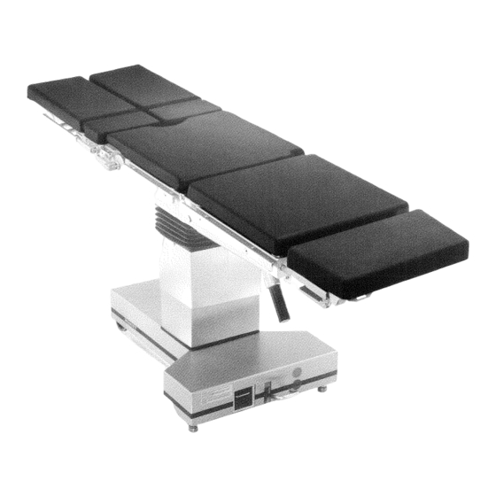
Maquet Betastar 1131 Manuals
Manuals and User Guides for Maquet Betastar 1131. We have
1
Maquet Betastar 1131 manual available for free PDF download: Maintenance & Repair Instructions
Maquet Betastar 1131 Maintenance & Repair Instructions (233 pages)
Brand:
Maquet
| Category:
Medical Equipment
| Size: 13.35 MB
Table of Contents
Table of Contents
3
Table of Contents
4
Product View
6
Padding and Covers
7
Table Top Padding (Lectrolite)
7
Table Top Pads (PU)
7
Removing the Base Cover (Models with Trapezoidal Base Only)
9
Removal of the Base Covers (Models with T-Shaped Base Only)
11
Column Casing
13
Castors and Locking Device
15
Replacing the Fixed Castors (Models with Trapezoid Base Only)
15
Replacing the Swivel Castors (Models with Trapezoid Base Only)
15
Replacing the Castor Bushing (Models with Trapezoid Base Only)
17
Cleaning and Maintenance of the Castors
19
Locking Cam Maintenance (Models with T-Shaped Base Only)
19
Replacing the Swivel Castors (Models with T-Shaped Base Only)
19
Wartung / Reinigung der Rollen
19
Replacing the Fixed Castors (Models with T-Shaped Base Only)
21
Replacing the Locking Cam (Models with T-Shaped Base Only)
21
Replacing the Pedal and the Pedal Shaft (Two Pieces)
21
Bockrollen
21
Replacing the Shaft at the Pedal Controlling Transverse Movement
23
Electrical Equipments
25
Replacing the Tappet, Spring and Rubber Stopper
23
3 Elektrische Einrichtungen
25
Removing the Transformer
25
Transformer with Circuit Board and Voltage Selector
25
Kabeltrommel
27
Battery Charger
29
Removing the Cable Reel (Models with T-Shaped Base Only)
27
Replacing the Battery Charger
31
Batterien
33
Replacing the Batteries
33
Replacing the DC Motor
35
Säulenverkleidungen
35
Hand Control Unit
37
Replacing the Valve Wiring and Cable
37
Ventilverdrahtung
37
Empfängerplatine, Programmspeicher
39
IR Receiver Board
39
Replacing the Flange Socket and Cover
39
Replacing the Receiver Board, Microcontroller
39
Setting the "0" Position Potentiometers for Tilt/Trendelenburg Control
41
Setting the "0" Position Potentiometers for the Back
43
Hydraulic Equipment
45
Hydraulic Pressure Hoses
45
4 Hydraulische Einrichtungen-
45
Elevation Cylinder and Guide
47
Observe Proper Installation Position
49
Adjustment of the Elevation Unit
53
Setting Amount of Play at Operating Table in Longitudinal Direction
55
Setting Amount of Play at Operating Table in Transverse Direction
55
Gimbal Joint/Trendelenburg Cylinder
57
Kardan-Gelenk
57
Guide Housing
59
Trendelenburg Cylinder
59
Lateral Tilt Cylinder/Hydraulic Power Unit
57
Führungsgehäuse
59
Hydraulikaggregat
61
Replacing the Hydraulic Power Unit
61
Back Cylinder (1223 and 1131 with Hydraulic-Powered Back Only)
63
Kantungszylinder
63
Tilt Cylinder
63
Leg Plate Cylinder ( Only 1211 )
65
Leg Plate Cylinders (12 11 Only)
65
Replacing the Valve Assembly
67
Ventilgruppe
67
Hydraulic Pump
69
Pressure Limiter Valve
69
Changing the Oil
71
Intake Filter
71
Oil Level
71
Saugfilter
71
Replacing the Orifice Plates in Control Valve Unit 1
73
Bowden Cable for Longitudinal Shift and Trendelenburg Cylinder
75
Grip and Spring
77
Table Top
75
5 Repair Works Table Top
77
Gas-Loaded Spring in the Left-Hand Rail (1131, 1211 Only)
77
Gas-Loaded Spring in the Right-Hand Rail (1131, 1211 Only)
79
Adjustment of Gas Spring Actuation (Right-Hand Handle)
81
Joint Clamp
85
Einstellung Exzenterhebel der Beinplatten
87
Resetting the Clamping Mechanism
87
Setting the Eccentric Lever at the Leg Plates
87
Adjusting the Eccentric Lever at the Head Rest
89
Einstellung Exzenterhebel der Kopfplatten
89
Technical Description
91
6 Technische Beschreibung
91
"0" Position
93
Sequence of Functions - Electrical and Hydraulic
93
7 Wartungsaufgaben
94
Maintenance Routines
95
Electrical Tests
95
Hydraulic Tests
95
Mechanical Tests
95
Auxiliary Components for Repair and Maintenance Operations
97
Repair Instructions
99
Survey
101
Tools Required
101
Dismounting of Hand Control
103
Mounting of Insert Nuts
105
Setting the Insert Nuts
105
Mounting of Spiral Cable
107
Mounting Instructions
111
Mounting the Buffer Bracket to Side of the Transformer Drawer
115
Mounting the Buffer Bracket to Side of the Battery Drawer
117
Mounting the Rubber Buffer
119
Mounting the Spacer Plate and Cover Rail
121
Survey Modifications
125
Mounting Instructions for Castor Conversion Kit
127
Jacking up the Operating Table
128
Removal of Base Cover
128
Removal of Swivel Castors
128
Mounting of Base Cover
130
Mounting of Swivel Castors
130
Retrofit Set Intermediate Plate for Valve Control Unit 1
135
Exchange of Welding Assemblies
140
Adjustment of Selflocking Device
142
Bore Hole/Thread for Prestress Screw to be Machined on Site
144
Instructions for Modification Set for Cable Reel
146
Attachment of T-Base Cover
147
Detachment of T-Base Cover
147
Jacking up of the Operating Table
147
Modification of Operating Table/Replacement of Old Cable Reel
147
Removal of Cable Reel
149
Assembly of the Cable Reel
151
Mounting the Buffer Bracket to Side of Transformer Drawer
156
Mounting Instructions for Retrofit Kit for Base Rails
159
Allgemeines
166
Seite/Page:
167
8. Anhang, Werkzeuge, Etc. 8.01 -
169
Seite/Page:
169
Batterien
171
Ladegerät
171
Motorschutz
173
Motortest
173
Messungen , (Tests), Hydraulik
179
Hydraulikzylinder
181
Ölstandskontrolle
181
Generals
196
Test Instructions, Troubleshooting
197
Design and Function
199
Batteries
201
Battery Charger Test
201
Measurements (Tests), Electric and Electronic System
201
Transformer Secondary Leads
201
Motor Test
203
Protective Motor Switch
203
0"- Position Potentiometers
205
Control Unit and Receiver Board
207
Measurements (Tests), Hydraulic System
209
Working Pressure
209
Checking the Oil Level
211
Hydraulic Cylinders
211
Leaks at the Check Valve
213
Leakage at the Control Valves (SV1 to SV6)
215
Motor Runs but no Function Executed Although Function Button Pressed
217
Motor Starts Without any of the Control Unit Buttons Being Pressed
217
Troubleshooting - What to Do, if
217
Operating Table Cannot be Operated Using the IR Remote Control
219
Red Light on the Control Unit Display
219
Height Function Does Not Move Upward and Moves Downward very Slowly
221
No Function of the O.R. Table at All
221
Acoustic Alarm Signals
223
Continuous Signal in the Column Head
223
Instructions for Gas-Spring Supported Adjustment of Back Section
225
Instructions for Gas Spring Back Section
226
Replacement and Adjustment of Gas Spring in Right-Hand Back Rail
227
Adjustment of Gas Spring Actuation - Right-Hand Handle
229
Instructions Gas Spring Back Section
230
Advertisement
Advertisement
Related Products
Maquet 1133.02BX
Maquet 1133.02BFX
Maquet 1133.12B1
Maquet 1133.12B3
Maquet 1133.12F1
Maquet 1133.12F3
Maquet Betamaquet 1140 10A
Maquet Betamaquet 1140 10B
Maquet Betamaquet 1140 20B
Maquet 111801
Maquet Categories
Medical Equipment
Fan
Heater
Air Compressor
More Maquet Manuals
Login
Sign In
OR
Sign in with Facebook
Sign in with Google
Upload manual
Upload from disk
Upload from URL