Sign In
Upload
Manuals
Brands
Magnum Manuals
Scales
TE100
Magnum TE100 Electronic Bagging Scale Manuals
Manuals and User Guides for Magnum TE100 Electronic Bagging Scale. We have
2
Magnum TE100 Electronic Bagging Scale manuals available for free PDF download: Operation And Maintenance Manual, Quick Reference Manual
Magnum TE100 Operation And Maintenance Manual (98 pages)
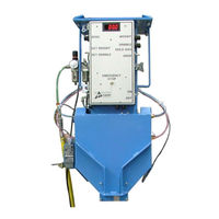
Electronic Small Bagging Scale
Brand:
Magnum
| Category:
Scales
| Size: 5.09 MB
Table of Contents
Table of Contents
7
1 Product Description
15
General Description
15
Introduction
15
Manual Scope
15
Electrical Requirements
15
Pneumatic Requirements
15
Major Systems and Components
16
Figure 1-1. TE100 Front View
16
Scale Cabinet Assembly
17
Scale Cabinet
17
Figure 1-2. Scale Cabinet and Shut off Gate
17
Shut off Gate
18
Shut off Gate Bearings
18
Shut off Gate Cylinder
18
Dribble Gate
18
Dribble Gate Cylinder
18
Dribble Gate Mounting Rails
18
Load Cell
18
Figure 1-3. Load Cell
18
MAC Valves
19
Figure 1-4. MAC Valves
19
Figure 1-5. MAC Valve Flow Adjustment
19
Filter/Regulator/Lubricator (FRL) Assembly
20
Control Panel
20
Figure 1-6. Filter/Regulator/Lubricator (FRL) Assembly
20
Figure 1-7. Control Panel
20
Spout Assembly
21
Spout
21
Figure 1-8. Spout Assembly
21
Bag Clamp Arms
22
Figure 1-9. Chain Links and Pivot Block
22
Figure 1-10. Bag Clamp Arm - Shown with Stainless Steel Deflector
22
Bag Clamp Cylinders
23
Bag Clamp Pads
23
Figure 1-11. Bag Clamp Cylinder (1 of 2 Shown)
23
Figure 1-12. Bag Clamp Pads
23
Start Switch
24
Bag Position Switch
24
Figure 1-13. Start Switch
24
Figure 1-14. Bag Position Switch
24
Figure 1-15. TE100 with Small Bag Adapter Installed
25
2 Receiving Equipment
27
General Description
27
Uncrating the Equipment
27
Figure 2-1. Typical Shipping Box (2 Boxes Shown)
27
3 Setup/Installation
29
General Description
29
Figure 3-1. Mounting the TE100
29
Mechanical Setup
30
Making Electrical Connections
30
Electrical Connections
30
Figure 3-2. Hanging the Cabinet Assembly on the Hopper Flange
30
Figure 3-3. Shipping Bracket Location
30
Figure 3-4. MAC Valve Connections and Schematic
31
Load Cell Connections
32
Making Pneumatic Connections
32
Lubrication Requirements
32
Figure 3-5. Load Cell Connections
32
Figure 3-6. Lubricator - Oil Flow Control
32
Dry Cycle
33
Calibration
33
Figure 3-7. Control Panel
34
Figure 3-8. Relay Board
35
Figure 3-9. Relay Board Schematic
35
Table 3-1. TE100 Operational Controls
36
Figure 3-10. Decimal Point Switches
37
Weight Display Setup
37
Figure 3-11. Display Trim Pot
38
Figure 3-12. ZERO Knob and Lock Collar
38
Zeroing the Weight Display
38
Calibration of Scale to Full-Scale Weight
39
Figure 3-14. Hanging a Certified Test Weight on the TE100
39
Figure 3-16. Coarse Weight Gain Switches
40
Adjusting Density Correction Setting
41
Table 3-2. Coarse Weight Gain Switch Combinations
41
Figure 3-18. Over/Under Reject Controls
43
Over/Under Reject Adjustments
43
Table 3-3. Over/Under Reject Dial Settings
43
Dribble Gate Setup
44
Figure 3-19. Dribble Gate Cylinder Mounting
44
Installing the Optional Small Bag Adapter
45
4 Operation
47
General Description
47
Operational Controls
47
Initial Setup
48
Figure 4-1. Control Panel
48
Figure 4-2. Over/Under Reject Controls
50
Table 4-1. Auto Correction Example (Target Weight = 50.0 Lbs)
50
Normal Operation (Typical Fill Cycle)
51
Table 4-2. Over/Under Reject Dial Settings (0 to 100 = 0.8 Lbs)
51
Maintaining Operational Efficiency
52
5 Preventive Maintenance
53
General Description
53
Daily Maintenance Procedures
53
Cleaning
53
Check Calibration
53
Monthly Maintenance
53
6 Troubleshooting
55
General Description
55
The Troubleshooting Process
55
Trouble Symptoms
55
Scale Is Not Accurate
55
Scale Does Not Return to Zero
56
The Machine Is Unable to Auto Correct to the Target Weight
56
The Weighments Fluctuate between too Light and too Heavy
56
Filled Bag Won't Drop
57
Bag Won't Stop Filling
57
Air Cylinder Failure
57
MAC Valve Failure
57
7 Repair and Adjustment
59
General Description
59
System Adjustments
59
Bag Clamp Adjustment
59
Figure 7-1. Pivot Block Setscrew Location (Setscrew Uninstalled Here)
59
Shut off Gate Adjustment
60
Figure 7-2. Shut off Gate Adjustment
60
MAC Valve Flow Control Adjustment
61
Figure 7-3. Adjusting Airflow from the MAC Valve
61
System Repairs
62
Spout Replacement
62
Spout Removal
62
Table 7-1. Bag Clamp Cylinder Air Supply Lines (1 Side Shown)
62
Spout Installation
63
Figure 7-4. Spout Mounting Bolts
63
Load Cell Replacement
64
Load Cell Removal
64
Load Cell Installation
64
Figure 7-5. Checking Load Cell Alignment (as Viewed from the Top of the TE100)
64
Dribble Gate Cylinder Replacement
65
Dribble Gate Cylinder Removal
65
Dribble Gate Cylinder Installation
65
Dribble Gate Replacement
65
Dribble Gate Removal
65
Dribble Gate Installation
65
Shut off Gate Cylinder Replacement
66
Shut off Gate Cylinder Removal
66
Shut off Gate Cylinder Installation
66
Shut off Gate Replacement
66
Shut off Gate Removal
66
Shut off Gate Installation
67
Figure 7-6. Shut off Gate Mounting
67
Figure 7-7. Shut off Gate Mounting Screw Ground off Smooth
67
Shut off Gate Seal Replacement
68
Shut off Gate Seal Removal
68
Shut off Gate Seal Installation
68
Bag Clamp Arm Replacement
68
Bag Clamp Arm Removal
68
Bag Clamp Arms Installation
69
Figure 7-9. Stainless Steel Deflector
69
Figure 7-10. Bag Clamp Arm Bolts and Bearings
69
Bag Clamp Arm Spring Replacement
70
Bag Clamp Arm Spring Removal
70
Figure 7-11. Bag Clamp Arm Bolts and Bearings Installed
70
Bag Clamp Arm Spring Installation
71
Bag Clamp Cylinder Replacement
71
Bag Clamp Cylinder Removal
71
Bag Clamp Cylinder Installation
71
Bag Clamp Pivot Block Replacement
72
Bag Clamp Pivot Block Removal
72
Bag Clamp Pivot Block Installation
72
Figure 7-12. Bag Clamp Pivot Block
72
Air Supply Line Replacement
73
Air Supply Line Removal
73
Air Supply Line Installation
73
Pneumatic Quick Connect Fitting Replacement
73
Pneumatic Quick Connect Fitting Removal
73
Figure 7-13. Air Supply Fitting
73
Pneumatic Quick Connect Fitting Installation
74
Main Circuit Board Replacement
74
Main Circuit Board Removal
74
Main Circuit Board Installation
74
Glossary
75
Index
78
Appendix A Safety Procedures
79
Appendix B Spare Parts
81
Table B-2. TE100 Spare Parts List
81
Appendix C Mechanical Drawings
83
Appendix D Electrical Drawings
93
Advertisement
Magnum TE100 Quick Reference Manual (2 pages)
Brand:
Magnum
| Category:
Scales
| Size: 0.11 MB
Advertisement
Related Products
Magnum T40I
Magnum T40AC
Magnum T40DC
Magnum Peak T5
Magnum Peak T7
Magnum Categories
Bicycle
Tuner
Transceiver
Paint Sprayer
Portable Generator
More Magnum Manuals
Login
Sign In
OR
Sign in with Facebook
Sign in with Google
Upload manual
Upload from disk
Upload from URL