Sign In
Upload
Manuals
Brands
Magnum Energy Manuals
Control Panel
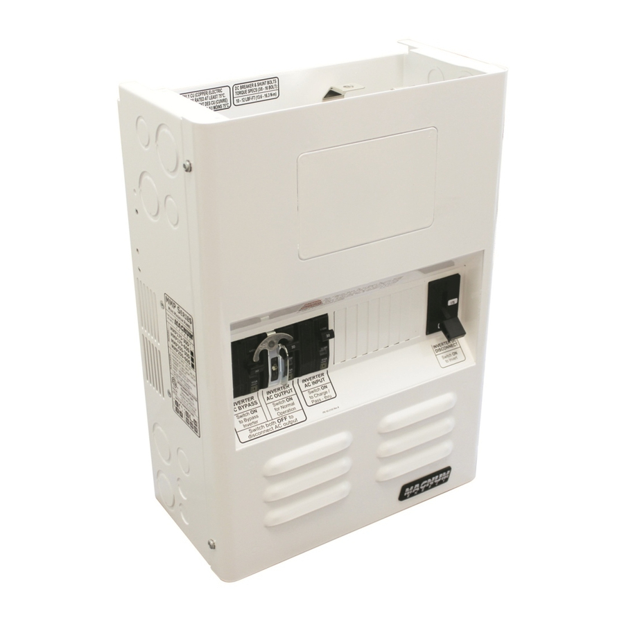
Mini Magnum Panel
User Manuals: Magnum Energy Mini Magnum Panel Enclosure
Manuals and User Guides for Magnum Energy Mini Magnum Panel Enclosure. We have
1
Magnum Energy Mini Magnum Panel Enclosure manual available for free PDF download: Owner's Manual
Magnum Energy Mini Magnum Panel Owner's Manual (70 pages)
Brand:
Magnum Energy
| Category:
Control Panel
| Size: 4 MB
Table of Contents
Important Safety Instructions
3
Safety Precautions
3
Table of Contents
7
1 Introduction
10
MMP Series Overview
11
MMP External Components
12
Figure 1-1, Mmp's Outside Components
12
MMP Internal Components
13
Figure 1-2, Mmpxxx-30D Internal Components
15
Figure 1-3, Mmpxxx-30D AC Breakers
15
Figure 1-4, Mmpxxx-60S Internal Components
16
Figure 1-5, Mmpxxx-60S AC Breakers
16
2 Installation
17
Preparation
17
Unpacking and Inspection
17
Required Materials and Tools
17
Figure 2-1, MMP Series Simplified Installation Diagram
18
Location
19
Conduit Knockouts
19
Figure 2-2, MMP Series Dimensions and Knockout Location/Sizes
20
Mounting
21
Figure 2-3, Removing Knockouts
21
Figure 2-4, Keyhole Locations for Mounting
22
Wiring the MMP Enclosure - General Requirements
23
Disconnect Switch and Overcurrent Protection
23
General Wiring Requirements
23
Wire Routing
24
Torque Requirements
24
Electrical System Wiring Diagrams
24
Table 2-1, Torque Values for Busbars
24
Table 2-2, Torque Values for the DC Shunt and DC Disconnect Breaker
24
Table 2-3, Torque Values for the AC Terminal Blocks
24
Figure 2-5, Mmpxxx-30D System Wiring Diagram
25
Figure 2-6, Mmpxxx-60S System Wiring Diagram
26
DC Wiring
27
DC Wiring Guidelines
27
DC Wiring Connection Points
28
Figure 2-7, DC Wiring Connection Points
28
Figure 2-8, DC Wiring with Magnum Inverter
29
Inverter DC Overcurrent Protection and DC Disconnect
30
Inverter and Battery Bank Wire Sizing
30
Table 2-4, Recommended DC Wire to MMP Enclosure
30
DC Hardware Connections
31
Figure 2-9, DC Connections - with Magnum Inverter Installed
31
Wiring the Battery Bank
32
Wiring the MMP Enclosure to the Battery Bank/Inverter
32
AC Wiring
33
AC Wiring Guidelines
33
AC Connections
33
Figure 2-10, AC Wiring Connections (Mmpxxx-30D Models)
34
Figure 2-11, AC Wiring Connections (Mmpxxx-60S Models)
35
AC Wire Size and Overcurrent Protection
36
AC Conductor Wiring
36
AC Wiring Confi Gurations
37
Table 2-5, AC Input/Output Wiring Configurations
37
Figure 2-12, AC Wiring for Single in - Single out (30 A) Configurations
38
Figure 2-13, AC Wiring for Single in - Single out (60 A) Configurations
39
Figure 2-14, AC Wiring for Dual in - Single out Configurations
40
Figure 2-15, AC Wiring for Dual in - Dual out Configurations
41
Mmp/Inverter System Grounding
42
Figure 2-16, Grounding System for Inverter with MMP Enclosure
42
Sizing the Grounding Electrode Conductors
43
Table 2-6, AC Grounding Electrode Conductor Sizing
43
Figure 2-17, Single Connection to DC Ground Rod (Method 1)
43
Figure 2-18, Multiple Connections to DC Ground Rod (Method 2)
44
Figure 2-19, Multiple Connections to DC Ground Rod (Method 3)
44
Equipment Grounding Conductor
45
System Bonding Jumper
45
Table 2-7, Equipment Grounding Conductor Sizing
45
Removing the AC Neutral to Ground Connection
46
Removing the DC Negative to Ground Busbar
46
Figure 2-20, Removing the AC Neutral to Ground Connection
46
Figure 2-21, Removing the DC Negative to Ground Busbar
46
Wiring Accessories
47
Figure 2-22, REMOTE Communication Cable (300V)
47
Figure 2-23, NETWORK Communication Cable (300V)
47
Figure 2-24, Extension Cable (300V)
47
Figure 2-25, Accessory Wiring Using 300 Volt Communications Cables
48
Installation Checklist
49
Functional Test
51
Figure 2-26, AC Voltage Checks
52
3 Operation
53
Figure 3-1, MMP Functional Diagram
53
Inverter DC Disconnect Breaker
54
AC Input Breaker
54
Inverter AC Output Breaker
54
Inverter AC Bypass Switch Breaker
54
Figure 3-2, Mmpxxx-30D Bypass Switch Operation
55
Figure 3-3, Mmpxxx-60S Bypass Switch Operation
56
Appendix A - Optional Equipment and Accessories
57
A1 Installing the Charge Controller Bracket
57
Table A-1, Mounting Holes Used for Charge Controllers
57
Figure A1-1, Charge Controller Bracket - Physical Dimensions
57
Figure A1-2, Charge Controller Bracket Mounting Holes
58
Figure A1-3, Holes Used to Mount Bracket on MMP Enclosure
59
A2 Installing a Remote Control
60
Figure A2-1, Installing a Remote Control on the MMP Enclosure
60
A3 Installing a Battery Monitor
61
Figure A3-1, Mounting the Sense Module
61
Figure A3-2, Wiring the Sense Module and DC Shunt
61
A4 Knockout Plate
62
Figure A4-1, Attaching Knockout Plate
62
Figure A4-2, Knockout Plate Dimensions and Knockouts
62
A5 Inverter Hood Info
63
Figure A5-1, Inverter Hood Dimensions
63
A6 MMP Back Panel Information
64
Figure A6-1, MMP Back Panel (BP-MMP) Information
64
A7 Installing Optional DC Breakers
65
Figure A7-1, Installing DIN Rail-Mounted DC Breakers
65
Figure A7-2, Installing Back Panel Mounted DC Breakers
66
Figure A7-3, Wiring DC Breakers
66
A8 Installing Lightning Arrestors
67
Figure A8-1, Installing Lightning Arrestor on MMP Enclosure
67
Figure A8-2, Wiring Lightning Arrestor to MMP Enclosure
68
Appendix B - Warranty and Service
69
B1 Limited Warranty
69
B2 How to Receive Repair Service
69
Advertisement
Advertisement
Related Products
Magnum Energy MM Series
Magnum Energy ME Series
Magnum Energy MagWeb GT
Magnum Energy ME-ARC50
Magnum Energy MagnaSine MS-PE Series
Magnum Energy MagnaSine MS4348PE
Magnum Energy MMS Series
Magnum Energy ME-SBC
Magnum Energy ME-ARC
Magnum Energy MSH3012M
Magnum Energy Categories
Inverter
Remote Control
Battery Charger
Adapter
Measuring Instruments
More Magnum Energy Manuals
Login
Sign In
OR
Sign in with Facebook
Sign in with Google
Upload manual
Upload from disk
Upload from URL