Table of Contents
Advertisement
Quick Links
Advertisement
Table of Contents

Summary of Contents for Magnum Energy Mini Magnum Panel
- Page 1 Mini Magnum Panel (MMP) Owner’s Manual...
- Page 2 Since the use of this manual and the conditions or methods of installation, operation, use and maintenance of the MMP enclosure (Mini Magnum Panel) is beyond the control of Magnum Energy, Inc., this company does not assume responsibility and expressly disclaims liability for loss, damage or expense, whether direct, indirect, consequential or incidental, arising out of or anyway connected with such installation, operation, use, or maintenance.
-
Page 3: Important Safety Instructions
• Overcurrent protection of the battery cables must be provided as part of the system installation. • Overcurrent protection of the AC output wiring must be provided as part of the system installation. Page ii © 2012 Magnum Energy, Inc. - Page 4 To prevent a spark at the battery and reduce the chance of explosion, always connect the cables to the batteries fi rst. Then connect the cables to the inverter. • Never charge a frozen battery. © 2012 Magnum Energy, Inc. Page iii...
- Page 5 Couple toutes les connexions de câblage ca et les connexions de câbles à courant continu à des valeurs de couple nécessaires. • La protection contre les surintensités des câbles de batterie doivent être fournis dans le cadre de l’installation du système. Page iv © 2012 Magnum Energy, Inc.
- Page 6 Our empêcher une étincelle à la batterie et réduire la possibilité de l’explosion, reliez toujours les câbles au rst de fi de batteries. • Reliez alors les câbles à l’inverseur. Ne chargez jamais une batterie congelée. © 2012 Magnum Energy, Inc. Page v...
-
Page 7: Table Of Contents
Wiring Accessories ..................38 2.14 Installation Checklist .................40 2.15 Functional Test ..................42 Operation ..................... 44 Inverter DC Disconnect Breaker ..............45 AC Input Breaker ..................45 Inverter AC Output Breaker ................45 Inverter AC Bypass Switch Breaker .............45 Page vi © 2012 Magnum Energy, Inc. - Page 8 Table 2-4, Recommended DC Wire to MMP Enclosure ............21 Table 2-5, AC Input/Output Wiring Configurations .............28 Table 2-6, AC Grounding Electrode Conductor Sizing ............34 Table 2-7, Equipment Grounding Conductor Sizing ............36 Table A-1, Mounting Holes Used for Charge Controllers ............48 © 2012 Magnum Energy, Inc. Page vii...
- Page 9 Figure A7-2, Installing Back Panel Mounted DC Breakers ............57 Figure A7-3, Wiring DC Breakers ..................57 Figure A8-1, Installing Lightning Arrestor on MMP Enclosure ..........58 Figure A8-2, Wiring Lightning Arrestor to MMP Enclosure ...........59 Page viii © 2012 Magnum Energy, Inc.
-
Page 10: Introduction
Introduction 1.0 Introduction Congratulations on your purchase of the Mini Magnum Panel (MMP) enclosure, part of a new line of panel systems from Magnum Energy. Installing an inverter system is now as simple as mounting the MMP enclosure, installing the inverter, connecting the battery bank, and if needed, bringing in AC power from a generator or the utility. -
Page 11: Mmp Series Overview
The MMP enclosure is available in four basic confi gurations. This section lists the four models and the enclosure’s main components and features. Individual Models: • MMP175-30D (Mini Magnum Panel, 175 ADC breaker, dual 30 AAC bypass/input breakers) • MMP175-60S (Mini Magnum Panel, 175 ADC breaker, single 60 AAC bypass/input breakers) •... -
Page 12: Mmp External Components
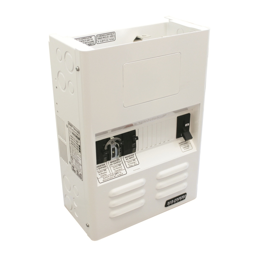
Front Cover – The front cover is removed to allow access to the internal components. Four #10 x 3/8”, T25 Torx drive screws are used to hold the front cover to the enclosure. Figure 1-1, MMP’s Outside Components © 2012 Magnum Energy, Inc. Page 3... -
Page 13: Mmp Internal Components
fl ow. See Section A3 in Appendix A for information on installing and wiring the ME-BMK-NS battery monitor inside the MMP enclosure. Battery Negative Connection – The bottom of the DC shunt is the connection point to the negative terminal of the battery bank. Page 4 © 2012 Magnum Energy, Inc. - Page 14 This busbar is rated to handle 120 amps, and has dual hole sizes—two # 14 to #1/0 AWG and fi ve #14 to #6 AWG—with screw type compression terminals (no ring lugs required). © 2012 Magnum Energy, Inc. Page 5...
-
Page 15: Figure 1-2, Mmpxxx-30D Internal Components
AC N EUTRAL ROUND ATTERY OSITIVE ONNECTION USBAR PV P OSITIVE USBAR ROUND USBAR DC N EGATIVE USBAR Figure 1-2, MMPxxx-30D Internal Components NVERTER NVERTER NVERTER NPUT YPASS UTPUT Figure 1-3, MMPxxx-30D AC Breakers Page 6 © 2012 Magnum Energy, Inc. -
Page 16: Figure 1-4, Mmpxxx-60S Internal Components
EUTRAL ATTERY OSITIVE ROUND USBAR ONNECTION PV P OSITIVE USBAR ROUND USBAR DC N EGATIVE USBAR Figure 1-4, MMPxxx-60S Internal Components NVERTER UTPUT NVERTER YPASS NVERTER NPUT IGHT Figure 1-5, MMPxxx-60S AC Breakers © 2012 Magnum Energy, Inc. Page 7... -
Page 17: Installation
• Four 8-32 x 1/2 Phillips drive, black colored screws (used to mount an optional remote control) If items appear to be missing or damaged, contact your authorized Magnum Energy dealer or Magnum Energy. Save your proof-of-purchase as a record of your ownership; it will also be needed if the unit should require in-warranty service. -
Page 18: Figure 2-1, Mmp Series Simplified Installation Diagram
(Magnum Options) NCLOSURE 0.5A Space for optional AC power to inverter DC circuit breakers ANEL and PV-GFP Inverter power (or pass-thru power) to Sub-panel ATTERY Figure 2-1, MMP Series Simplifi ed Installation Diagram © 2012 Magnum Energy, Inc. Page 9... -
Page 19: Location
Additional wiring from any external DC source (PV, wind, or hydro) to the MMP enclosure • Small signal wiring (battery sensors, battery monitoring, auto gen starting) • Attaching lightning arrestors • PV charge controller wiring Page 10 © 2012 Magnum Energy, Inc. -
Page 20: Figure 2-2, Mmp Series Dimensions And Knockout Location/Sizes
A = ½” (x4) ” B = ½” and ¾” (x8) C = 1” and 1¼” (x10) D = 1 ½” and 2” (x1) OTTOM Figure 2-2, MMP Series Dimensions and Knockout Location/Sizes © 2012 Magnum Energy, Inc. Page 11... -
Page 21: Mounting
Common building materials such as gypsum board as well as any paint, wall coverings, and certainly wood will not pass. Page 12 © 2012 Magnum Energy, Inc. -
Page 22: Figure 2-4, Keyhole Locations For Mounting
ACKPLATE 13 ” AGNUM 34 ” NVERTER 18 ” NCLOSURE 11 ” EYHOLE ETAIL 0.465" 0.409" 0.28 Ø 11 ” 0.438" 12 ” EYHOLES WITH OUNTING CREWS Figure 2-4, Keyhole Locations for Mounting © 2012 Magnum Energy, Inc. Page 13... -
Page 23: Wiring The Mmp Enclosure - General Requirements
300 volts, which allows 120/240 VAC inverters to be installed. If installing a 120/240 VAC inverter, the installer must also provide wires (both power and communication) with the insulation rated for at least 300 volts. Page 14 © 2012 Magnum Energy, Inc. -
Page 24: Wire Routing
They are not intended to override or restrict any national or local electrical codes; and, the diagrams should not be the determining factor as to whether the installation is compliant, that is the responsibility of the electrician and the on-site inspector. © 2012 Magnum Energy, Inc. Page 15... -
Page 25: Figure 2-5, Mmpxxx-30D System Wiring Diagram
DC ATTERY to ground (DC S 120V 240V 120V OURCE connections. AC S AC M ANEL ANEL WIRING (AC S NVERTER OADS OURCE Figure 2-5, MMPxxx-30D System Wiring Diagram Page 16 © 2012 Magnum Energy, Inc. -
Page 26: Figure 2-6, Mmpxxx-60S System Wiring Diagram
ATTERY DC to ground 120V 120V (DC S OURCE connections. AC S AC M ANEL ANEL WIRING (AC S NVERTER OADS OURCE Figure 2-6, MMPxxx-60S System Wiring Diagram © 2012 Magnum Energy, Inc. Page 17... -
Page 27: Dc Wiring
• Ensure the color code for the DC cables/wires are correct: RED for positive (+); WHITE for negative (–); and GREEN, GREEN/YELLOW, or bare for DC equipment grounds. Page 18 © 2012 Magnum Energy, Inc. -
Page 28: Dc Wiring Connection Points
DC load circuit breakers. Battery Positive Connection – Serves as the battery positive connection point for additional DC circuits (from charge controller output or connecting to DC load breakers). © 2012 Magnum Energy, Inc. Page 19... -
Page 29: Figure 2-8, Dc Wiring With Magnum Inverter
BTS cable Battery Bank’s Equipment Ground Wire Battery Bank’s Negative Cable Battery Bank’s Positive Cable DC System Grounding point [Electrode Conductor (i.e., ground busbar)] Battery Bank Figure 2-8, DC Wiring with Magnum Inverter Page 20 © 2012 Magnum Energy, Inc. -
Page 30: Inverter Dc Overcurrent Protection And Dc Disconnect
Note – Wire must be copper with a minimum rating of 300V, 75°C at an ambient temperature of 30°C. Note – See Section 2.10 for more information on the equipment grounding wire size. © 2012 Magnum Energy, Inc. Page 21... -
Page 31: Dc Hardware Connections
2 Pos. (+) battery cable lug 3 Split-lock washer 4 Hex bolt (3/8-16) DO NOT place anything between the DC breaker terminal and the positive battery cable lug. Figure 2-9, DC Connections – with Magnum Inverter Installed Page 22 © 2012 Magnum Energy, Inc. -
Page 32: Wiring The Battery Bank
4. Route an appropriately sized DC grounding wire (green or bare wire) from the inverter’s DC equipment ground terminal and from the battery bank enclosure to the DC ground busbar in the MMP enclosure. Refer to Section 2.10 for grounding information and sizing the DC ground wires. © 2012 Magnum Energy, Inc. Page 23... -
Page 33: Ac Wiring
AC system, this connection must be disconnected. See Section 2.11 for information to disconnect this connection. Note – MS2012/MS2000 (-15B and -20B) breaker models do not require a dedicated inverter sub-panel. Page 24 © 2012 Magnum Energy, Inc. -
Page 34: Figure 2-10, Ac Wiring Connections (Mmpxxx-30D Models)
AC load panel ground) AC HOT 1 IN (from L1 side of utility or generator) AC NEUTRAL IN (from neutral of utility or generator) Figure 2-10, AC Wiring Connections (MMPxxx-30D Models) © 2012 Magnum Energy, Inc. Page 25... -
Page 35: Figure 2-11, Ac Wiring Connections (Mmpxxx-60S Models)
AC HOT IN (from utility/generator ground (from hot out of utility or generator) and to AC load panel ground) AC NEUTRAL IN (from neutral of utility or generator) Figure 2-11, AC Wiring Connections (MMPxxx-60S Models) Page 26 © 2012 Magnum Energy, Inc. -
Page 36: Ac Wire Size And Overcurrent Protection
– On Magnum MS2012/MS2000 (-15B and -20B) breaker models, the pass-thru current is limited by the output breaker size. Note – This wire must be copper with a minimum rating of 300V, 75°C. © 2012 Magnum Energy, Inc. Page 27... -
Page 37: Ac Wiring Confi Gurations
: The MS2012 and MS2000 models with integral branch circuit rated output breakers (i.e. MS2012- 20B) allows direct wiring from the unit to the load and do not require an inverter sub-panel. Note : Based on AC input breaker provided. Page 28 © 2012 Magnum Energy, Inc. -
Page 38: Figure 2-12, Ac Wiring For Single In - Single Out (30 A) Configurations
..AC OUT AC IN (to AC loads) (from grid/gen) Main Panel .Sub-Panel and Outlets (Utility/Generator 30A) (Inverter AC Loads) Figure 2-12, AC Wiring for Single In – Single Out (30 A) Confi gurations © 2012 Magnum Energy, Inc. Page 29... -
Page 39: Figure 2-13, Ac Wiring For Single In - Single Out (60 A) Configurations
.AC OUT AC IN (to AC loads) (from grid/gen) Main Panel Sub-Panel and Outlets (Utility/Generator 60A) (Inverter AC Loads) Figure 2-13, AC Wiring for Single In – Single Out (60 A) Confi gurations Page 30 © 2012 Magnum Energy, Inc. -
Page 40: Figure 2-14, Ac Wiring For Dual In - Single Out Configurations
.AC OUT AC IN (to AC loads) (from grid/gen) Main Panel Sub-Panel and Outlets (Utility/Generator 30A per leg) (Inverter AC Loads) Figure 2-14, AC Wiring for Dual In – Single Out Confi gurations © 2012 Magnum Energy, Inc. Page 31... -
Page 41: Figure 2-15, Ac Wiring For Dual In - Dual Out Configurations
.AC OUT AC IN (to AC loads) (from grid/gen) Main Panel Sub-Panel and Outlets (Utility/Generator 30A per leg) (Inverter AC Loads) Figure 2-15, AC Wiring for Dual In – Dual Out Confi gurations Page 32 © 2012 Magnum Energy, Inc. -
Page 42: Mmp/Inverter System Grounding
OURCE HOT 1 GC-AC GC-DC HOT 2 NEUT NCLOSURE GEC-AC GEC-DC Grounding System AC side dedicated AC and DC sides shared DC side dedicated Figure 2-16, Grounding System for Inverter with MMP Enclosure © 2012 Magnum Energy, Inc. Page 33... -
Page 43: Sizing The Grounding Electrode Conductors
NVERTER System System AC P ANEL OURCE OURCE HOT 1 GC-DC GC-AC HOT 2 NEUT GEC-AC NCLOSURE GEC-DC Grounding System DC side dedicated Figure 2-17, Single Connection to DC Ground Rod (Method 1) Page 34 © 2012 Magnum Energy, Inc. -
Page 44: Figure 2-18, Multiple Connections To Dc Ground Rod (Method 2)
AC P ANEL OURCE OURCE HOT 1 GC-DC GC-AC HOT 2 NEUT NCLOSURE GEC-AC GEC-DC AC side dedicated Grounding System DC side dedicated Figure 2-19, Multiple Connections to DC Ground Rod (Method 3) © 2012 Magnum Energy, Inc. Page 35... -
Page 45: Equipment Grounding Conductor
DC main electrical distribution panel or PV-GFP device), the Negative to Ground busbar (Item 1, Figure 1-2 or 1-4) MUST BE REMOVED inside the MMP enclosure. See Section 2.12 to remove this negative-ground connection. Page 36 © 2012 Magnum Energy, Inc. -
Page 46: Removing The Ac Neutral To Ground Connection
DC shunt. Ensure the hardware on the bottom terminal of the DC shunt is stacked correctly. Note: Refer to Figure 2-9 Figure 2-21, Removing the DC to correctly stack the DC shunt hardware. Negative to Ground Busbar © 2012 Magnum Energy, Inc. Page 37... -
Page 47: Wiring Accessories
ME-BTS (Battery Temperature Sensor). After connecting to the ME-BTS, this extension cable is routed inside the MMP enclosure and connects to the inverter’s BTS port as shown in Figure 2-25. Figure 2-24, Extension Cable (300V) Page 38 © 2012 Magnum Energy, Inc. -
Page 48: Figure 2-25, Accessory Wiring Using 300 Volt Communications Cables
Cable (300-volt rated) REMOTE Communication Cable (300-volt rated) Front cover of MMP enclosure (back side) REMOTE ME-RC or ME-ARC ME-BTS Extension Cable (300-volt rated) Figure 2-25, Accessory Wiring using 300 Volt Communications Cables © 2012 Magnum Energy, Inc. Page 39... -
Page 49: Installation Checklist
Terminals containing more than one conductor are listed for multiple conductors. Connectors using fl exible, fi ne-stranded conductors are listed for use with such conductors. Re-torque electrical terminal connections in the inverter that may have loosened. Page 40 © 2012 Magnum Energy, Inc. - Page 50 Local codes may modify the requirements of the NEC/CEC. Part of this checklist is obtained from the Photovoltaic Electrical Power Systems Inspector/Installer Checklist created by John Wiles, Southwest Technology Development Institute, New Mexico State University, June, 2006. © 2012 Magnum Energy, Inc. Page 41...
-
Page 51: Functional Test
Note¹ – On MMPxxx-60S models, the INV OUT and INV IN breakers are physically ganged together and turn ON and OFF as a single breaker. Note – The INV BYP and INV OUT breakers are interlocked together. Physically turning ON will turn OFF the other, and vice-versa. Page 42 © 2012 Magnum Energy, Inc. -
Page 52: Figure 2-26, Ac Voltage Checks
ENCLOSURE 120V AC O UTPUT ERMINALS 240V 120V TO INVERTER LOADS 120V AC I 120V NPUT ERMINALS 120V 240V FROM UTILITY OR GENERATOR 120V -60S -30D ODELS ODELS Figure 2-26, AC Voltage Checks © 2012 Magnum Energy, Inc. Page 43... -
Page 53: Operation
SOURCE LOADS FROM MAIN IN SUB- AC INPUT PANEL PANEL Breakers USTOMER USTOMER ONNECTION ONNECTION INVERTER AC Terminal Block INV IN INV OUT INVERTER INPUT OUTPUT (AC side) Figure 3-1, MMP Functional Diagram Page 44 © 2012 Magnum Energy, Inc. -
Page 54: Inverter Dc Disconnect Breaker
Info: When the bypass switch is ON the connected equipment is directly powered from the AC source (utility or generator), and will go off if the AC source is disconnected or turned off. © 2012 Magnum Energy, Inc. Page 45... -
Page 55: Figure 3-2, Mmpxxx-30D Bypass Switch Operation
MMP enclosure to be serviced. To service the inverter, the Inv Input breaker must also be turned OFF. Figure 3-2, MMPxxx-30D Bypass Switch Operation Page 46 © 2012 Magnum Energy, Inc. -
Page 56: Figure 3-3, Mmpxxx-60S Bypass Switch Operation
This allows the inverter, the loads in the sub-panel, or any installed equipment beyond the MMP enclosure to be serviced. Figure 3-3, MMPxxx-60S Bypass Switch Operation © 2012 Magnum Energy, Inc. Page 47... -
Page 57: Appendix A - Optional Equipment And Accessories
Classic w/Turbo (MN) (A) / [upper] (F) / [upper] FlexMax 80 (OB) (G) and (E) / [upper] Tristar (MS) (D) / [lower] (C) / [lower] (MN) = MidNite, (OB) = OutBack, (MS) = MorningStar Page 48 © 2012 Magnum Energy, Inc. -
Page 58: Figure A1-2, Charge Controller Bracket Mounting Holes
Mounting Holes Charge Control Bracket Enclosure (left side) Right Front View Controller Bracket Enclosure Mounting Holes Charge Control Bracket Bracket to enclosure (right side) Torx screws Figure A1-2, Charge Controller Bracket Mounting Holes © 2012 Magnum Energy, Inc. Page 49... -
Page 59: Figure A1-3, Holes Used To Mount Bracket On Mmp Enclosure
Charge Control Bracket Holes (left side) (left side) Lower Mounting Holes (left side) Controller Mounting Bracket to enclosure Torx screws Holes on Bracket MMP Enclosure Figure A1-3, Holes Used to Mount Bracket on MMP Enclosure Page 50 © 2012 Magnum Energy, Inc. -
Page 60: A2 Installing A Remote Control
RJ14 jack on the backside of the remote. LANK LATE RONT OVER RONT OVER REAR VIEW FRONT VIEW Figure A2-1, Installing a Remote Control on the MMP Enclosure © 2012 Magnum Energy, Inc. Page 51... -
Page 61: A3 Installing A Battery Monitor
Communications Cable (To Network port on Magnum inverter) Close-up of wiring the ME-BMK To Battery Bank DC Negative Busbar (in MMP Enclosure) Figure A3-2, Wiring the Sense Module and DC Shunt Page 52 © 2012 Magnum Energy, Inc. -
Page 62: A4 Knockout Plate
NOCKOUTS OTAL B = ½” and ¾” (x2) C = 1” and 1¼” (x2) D = 1 ½” and 2” (x1) Figure A4-2, Knockout Figure A4-1, Attaching Knockout Plate Plate Dimensions and Knockouts © 2012 Magnum Energy, Inc. Page 53... -
Page 63: A5 Inverter Hood Info
2. Do not place anything on top of the hood that might cause it to bend downward; or, place anything on the sides to restrict air fl ow through the inverter. 8" 1" 90° 90° 3" (inches) 0.65 1" 3" 0.28 0.28 1" 0.85 13.60" 14.45" Figure A5-1, Inverter Hood Dimensions Page 54 © 2012 Magnum Energy, Inc. -
Page 64: A6 Mmp Back Panel Information
Notes: 6. Includes ten 1/4-20 x 3/4” Hex bolts; for mounting the MMP enclosure, 1. All dimensions are in inches. a Magnum Energy inverter, and the inverter hood. Detail A 2. Material = 16 gauge steel. 7. The outside holes on the left and right side measure 16” center-to-center. -
Page 65: A7 Installing Optional Dc Breakers
Note² – For the 1” back-mounted breakers, use E-Frame types (E Series by Carling Technologies, 209 Series by Airpax/Sensata Technologies or CF Series by Heinemann/Eaton). RAIL RAIL MOUNTED BREAKER (1/2” MOUNTING TRACK WIDTH Figure A7-1, Installing DIN Rail-Mounted DC Breakers Page 56 © 2012 Magnum Energy, Inc. -
Page 66: Figure A7-2, Installing Back Panel Mounted Dc Breakers
USBAR O BATTERY BANK POSITIVE TERMINAL ANELS DC N PV + ROUND EGATIVE USBAR USBAR USBAR O BATTERY BANK RIMARY NEGATIVE TERMINAL ROUND YSTEM DC S THROUGH HUNT Figure A7-3, Wiring DC Breakers © 2012 Magnum Energy, Inc. Page 57... -
Page 67: A8 Installing Lightning Arrestors
Info: For more information on lightning protection in RE systems, review Protection Against the Effects of Lightning on Standalone Photovoltaic Systems – Common Practices at www.iea-pvps.org. Enclosure Lightning ½” knockout ½” lock Arrestor removed washer Figure A8-1, Installing Lightning Arrestor on MMP Enclosure Page 58 © 2012 Magnum Energy, Inc. -
Page 68: Figure A8-2, Wiring Lightning Arrestor To Mmp Enclosure
Info: Readily used service entrance connectors are available at most electrical dealers – for example, the Type SX manufactured by Ilsco (www.ilsco.com), or the Type N manufactured by Thomas and Betts (www.tnb.com). © 2012 Magnum Energy, Inc. Page 59... -
Page 69: Appendix B - Warranty And Service
5. The original purchaser shall return the product prepaid to Magnum Energy in Everett, WA. After the completion of service under this limited warranty, Magnum Energy will return the product prepaid to the original purchaser via a Magnum-selected non-expedited surface freight within the contiguous United States and Canada;... - Page 70 Magnum Energy, Inc. 2211 West Casino Rd. Everett, WA 98204 Phone: 425-353-8833 Fax: 425-353-8390 Web: www.magnumenergy.com MMP Owner’s Manual (PN: 64-0029 Rev D)
Need help?
Do you have a question about the Mini Magnum Panel and is the answer not in the manual?
Questions and answers