Sign In
Upload
Manuals
Brands
Magnetek Manuals
Elevators
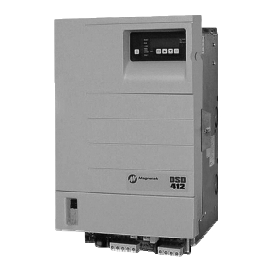
DSD 412
Magnetek DSD 412 Manuals
Manuals and User Guides for Magnetek DSD 412. We have
2
Magnetek DSD 412 manuals available for free PDF download: Technical Manual
Magnetek DSD 412 Technical Manual (122 pages)
DC Elevator Drive
Brand:
Magnetek
| Category:
DC Drives
| Size: 1 MB
Table of Contents
Warranty
2
Table of Contents
3
Table 1: Drive Parameters
11
Table 2: Monitor Functions
12
Table 3: Misc Commands
12
Table 4: Fault References
14
Introduction
15
Drive Description
15
The Standard Control Display Unit (SCDU)
15
The Portable Control Display Unit (PCDU)
15
Drive Ratings and Specifications
15
Basic Drive Specifications
15
Service Conditions
15
Protective Features
15
Figure 1: DSD 412 Block Diagram a
16
Figure 2: DSD 412 Block Diagram B
17
Figure 3: Component Layout Front View
18
Figure 4: Component Layout Right Side View
19
Power Conversion Unit
20
Description
20
Hardware Descriptions
20
DSD 412 Power Supply PCB (A4)
20
Armature Interface PCB (A2)
20
Scr's
21
Field Interface PCB (A3)
21
Cell Snubber PCB (A5)
21
Drive Control PCB (A1)
21
Precautionary Statements
23
How to Contact Magnetek
23
Pre-Installation Considerations
24
Receipt of Shipment
24
Unpacking Instructions
24
Packing Instructions for Reshipment or Storage
24
Physical Installation
24
Selecting, Mounting and Wiring of the Digital Encoder
24
Figure 5: Common Problems in Encoder Mounting
25
Electrical Hook up
26
Power Connections
26
Signal Connections
26
Grounding
26
Pre-Power Check
26
Drive Start up
27
Drive Power-Up Sequence
27
Abnormal Display Conditions
27
Fan Check
27
Verify Parameters
27
Figure 6: Typical Power Wiring
29
Figure 7: Typical Analog Signal Wiring
30
Figure 8: Typical Serial Signal Wiring
31
Figure 9: Power/ Signal Wiring Notes
32
Figure 10: Drive Brake Control Feature
33
Figure 11: Speed Select Logic Input Wiring
34
Standard Control/Display Unit Operation
35
General
35
Start-Up Operation
35
After Power-Up
36
Changing Parameter Functions
36
Viewing Monitor Functions
37
Error Reporting
38
Fault Display/Clear
40
Error Display
40
Non-Volatile Ram Access
41
Load Default Function
42
Self Tune Function
42
Power Conversion Diagnostics
44
Drive Setup & Adjustments
46
Software Operating Features
46
Motor Field Current Control
46
Analog Velocity Follower
47
Internal Preset Speed & Profile Generator
47
Serial Link Follower
47
Maintainance Mode - Armature Voltage Feedback
47
Pre-Torque
47
Current Ramp-Down
47
Electronic Motor Over-Load
48
External/Auto Fault Reset
48
Over-Speed Test
48
Anti-Rollback (ARB)
48
Drive Standby Power Reduction (DSPR)
48
Brake Control Logic
48
Adjustment Function Descriptions
49
Table 5: Binary Preset Speed Select
58
Table 6: Progressive Preset Speed Operation
58
Figure 12: S-Curve Accel/Decel Cycle
61
Figure 13: S-Curve Accel with Min %S
61
Figure 14: S-Curve with 100% S
61
Table 7: Programmable Output Selections
63
Table 8: Notch Period Steps
63
Table 9: Cube I.D. Number
66
Table 10: Field Current Range
66
Drive Set-Up
67
Field Regulator Set-Up
67
AC Input Voltage Requirement & Adjustment
67
Speed Regulator Adjustment
67
Figure 15: E-REG Tracking Profiles
70
Figure 16: E-REG Tracking Profiles
70
Figure 17: E-REG Tracking Profiles
71
Figure 18: Motor Overload
72
Figure 19: Elevator Start - Stop Timing
74
Table 11: Binary Input Control
76
Table 12: Progressive Input Control
76
Figure 20: Analog Signal Ground Noise
79
Figure 21: Serial Link Connections
79
Drive Faults
88
Function Error Code Listing
88
Troubleshooting
89
Table 13: Fault Code Descriptions
97
Figure 22: Other Faulting Conditions
98
Input - Output Signal Verification
99
Figure 23: I/O Monitor Function
99
Maintenance
100
Preventive Maintenance
100
Repair and Replacement Procedures
100
Printed Circuit Boards
100
Table 14: Connector Definitions
101
Figure 24: Connector and E-Prom Locations
102
Figure 25: Test Point Locations
103
Table 15: Test Point Definitions
105
Drive Control PCB Replacement
106
IC Replacement
106
Testing and Replacement of Power Components
106
Testing and Replacement of Power Semiconductors and Snubber Components
107
Testing and Replacement of the Motor Field Control Module and PCB
107
Repair of the 195Amp Assembly
108
Table 16: SCR Gate Resistance Testing
108
Repair of 300Amp Assembly
110
Spare Parts
113
Table 17: Spare Parts
114
Figure 26: Drive Chassis Outline, DSD 412, 100 Amp
115
Figure 27: Drive Chassis Outline, DSD 412, 195 Amp
116
Figure 28: Drive Chasis Outline, DSD 412, 300 Amp
117
Figure 29: Layout, DSD 412, 100 Amp
118
Figure 30: Layout, DSD 412, 195 Amp
119
Advertisement
Magnetek DSD 412 Technical Manual (124 pages)
DC Elevator Drive
Brand:
Magnetek
| Category:
Elevators
| Size: 1 MB
Table of Contents
Table of Contents
3
Introduction
13
Drive Description
13
The Standard Control Display Unit (SCDU)
13
The Portable Control Display Unit (PCDU)
13
Drive Ratings and Specifications
13
Basic Drive Specifications
13
Service Conditions
13
Protective Features
13
Software Operating Features
14
Power Conversion Unit
19
Description
19
Hardware Descriptions
19
DSD 412 Power Supply PCB (A4)
19
Armature Interface PCB (A2)
19
Scr's
20
Field Interface PCB (A3)
20
Cell Snubber PCB (A5)
20
Drive Control PCB (A1)
20
Precautionary Statements
22
How to Contact Magnetek
22
Pre-Installation Considerations
23
Receipt of Shipment
23
Unpacking Instructions
23
Packing Instructions for Reshipment or Storage
23
Physical Installation
23
Selecting, Mounting and Wiring of the Digital Encoder
23
Encoder Selection
23
Mounting
23
Coupling
24
Exceeding Operating Specification
24
Electrical Hook up
25
Power Connections
25
Signal Connections
25
Grounding
25
Pre-Power Check
25
Drive Start up
26
Drive Power-Up Sequence
26
Abnormal Display Conditions
26
Fan Check
26
Verify Parameters
26
Interconnect Drawings
27
Standard Control/Display Unit Operation
33
General
33
Start-Up Operation
33
After Power-Up
34
Changing Parameter Functions
34
Viewing Monitor Functions
35
Error Reporting
35
Fault Display/Clear
37
Error Display
37
Non-Volatile Ram Access
38
Load Default Function
39
Self Tune Function
39
Power Conversion Diagnostics
41
Drive Setup & Adjustments
43
Motor Field Current Control
43
Analog Velocity Follower
43
Internal Preset Speed & Profile Generator
43
Serial Link Follower
43
Armature Voltage Feedback
43
Pre-Torque, Function #114
43
Current Ramp-Down, Function #85
43
Electronic Motor Over-Load
44
External/Auto Fault Reset, Function #101
44
Over-Speed Test, Functions #80 and #81
44
Brake Control Logic, Functions #186 and #183
44
Speed Regulator Adjustment/E-Reg
45
Field Regulator Set-Up
47
AC Input Voltage Requirement & Adjustment
47
Adjustment Function Descriptions
61
Display Monitor Functions
78
Miscellaneous Functions
80
Drive Faults
81
Function Error Code Listing
81
Troubleshooting
82
Input - Output Signal Verification
91
Maintenance
93
Preventive Maintenance
93
Repair and Replacement Procedures
93
Printed Circuit Boards
93
Drive Control PCB Replacement
99
IC Replacement
99
Testing and Replacement of Power Components
99
Testing and Replacement of Power Semiconductors and Snubber Components
100
Testing and Replacement of the Motor Field Control Module and PCB
100
Repair of the 195Amp Assembly
101
Repair of the 300Amp Assembly
102
Appendix
106
Drive Ratings for Elevator Applications
106
Power Loss
107
Wire Terminal Specs
108
Power Terminal Wire Sizes
108
Ground Wire Sizes
108
Field Interface Board (TB1, TB4)
108
Spare Parts
109
Packing Instructions
112
Outline Drawings
113
Index
119
Advertisement
Related Products
Magnetek DLS4
Magnetek SMART TRAC DM6420
Magnetek OmniPulse DDC 2 Series
Magnetek Categories
Remote Control
Controller
Transmitter
DC Drives
Receiver
More Magnetek Manuals
Login
Sign In
OR
Sign in with Facebook
Sign in with Google
Upload manual
Upload from disk
Upload from URL