
User Manuals: Maggi BIG 800 Radial Arm Saw
Manuals and User Guides for Maggi BIG 800 Radial Arm Saw. We have 2 Maggi BIG 800 Radial Arm Saw manuals available for free PDF download: Manual
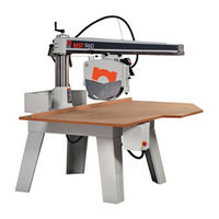
Maggi BIG 800 Manual (185 pages)
Radial Arm Saws
Table of Contents
-
Luku4
-
Dimensions11
-
Ausmasse37
-
Abschaltung38
-
Lärmemission50
-
Afmetingen63
-
Het Zaagblad68
-
Van Arm "A69
-
Luchtgeluid76
-
Dimensioner89
-
Pladen94
-
Luftbåren Støj102
-
Koneen Kuvaus111
-
Tekniset Tiedot113
-
Mitat115
-
Luku 2 - Asennus117
-
Käyttö Ja SääDöt122
-
Luku 4 - Huolto126
-
Alueen Meluisuus128
-
Ordering Note136
-
Ersatzteile136
-
Tavlefortegnelse138
Advertisement
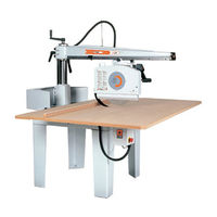
Maggi BIG 800 Manual (185 pages)
RADIAL ARM SAWS
Table of Contents
-
Dimensions11
-
Dati Tecnici61
-
Uso Previsto61
-
Dimensioni63
-
DI Taglio73
-
Lavoro73
-
Seguridad85
-
Dimensiones89
-
Trabajo99
-
Vertical101
-
Ruido Aereo102
-
Veiligheid111
-
Afmetingen115
-
Geleiders127
-
Cale Zuil127
-
Luchtgeluid128
-
Ordering Note136
-
Bon De Commande136
-
Notas De Pedido137
-
Tables Contents138
Advertisement