Sign In
Upload
Manuals
Brands
Macon Manuals
Controller
SWM7S/048-25
Macon SWM7S/048-25 Manuals
Manuals and User Guides for Macon SWM7S/048-25. We have
1
Macon SWM7S/048-25 manual available for free PDF download: User Manual
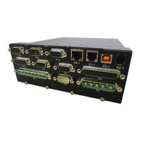
Macon SWM7S/048-25 User Manual (183 pages)
SINE WAVE COMMUTATED SERVO MODULE
Brand:
Macon
| Category:
Controller
| Size: 10 MB
Table of Contents
Table of Contents
3
Introduction
9
About this Manual
10
Safety Instructions
10
Typographical Conventions
10
Handling and Package
11
Packaging, Transport and Storage
11
Maintenance and Cleaning
11
Unmounting the Controller
11
Repair Instructions
12
Disposal
12
Package
12
Type Label
13
Hardware Revision
13
Firmware Revision
13
Tab. 2.1: SWM7S Type Plate (Example)
13
Capacitor Reforming Process after Long Storage Times
14
Technical Description
15
Family of Digital Servo Controllers
15
Drive with Linear Power Stage (Non-Switching)
16
Technical Data
16
Tab. 3.1: Temperature Range Options
16
Tab. 3.2: Cooling Options: (Specified Current Ratings Valid for Baseplate Temperatures below 40°C)
16
Tab. 3.3: SWM7 General Electrical Data
17
Tab. 3.4: Current-Sense: Dependency of ADC Sampling Frequency from PWM Frequency
17
Ambient Conditions, Ventilation and Mounting
18
Tab. 3.5: SWM7 Accessories
18
Tab. 3.6: SWM7 Environmental Data
18
Dimensions
19
Ground Systems
19
Application Hints and Warnings
19
Tab. 3.7: SWM7 Dimensions
19
Mechanical Installation
20
Safety Instructions
20
Mechanical
20
Thermal
21
Air Cooling (AC) Option
21
Water Cooling (WC) Option
21
Contact Cooling (Standard Device)
21
Electrical
21
Drawings
22
Base Plate SWM7S-150 and -300
22
Base Plate SWM7-48/100
23
Base Plate SWM7-600/50
24
SWM7S/600-25-Xt
25
SWM7S/600-25-XX-AC1
26
SWM7S/600-25-XX-WC
27
Base Plate SWM7S-48/150
28
SWM7 -300 V / -600 V Wall-Mount Version, High Voltage
29
Electrical Installation
31
Safety Instructions
31
Installation Instructions
32
General Connection Scheme
33
SWM7S-150: Connector Assignment
34
SWM7-150 with Extended I/Os: Connector Assignment
35
SWM7-48/100: Connector Assignment
36
SWM7-300/600: Connector Assignment
37
Power Supply
38
Temperature Supervision (X3)
38
Enable Interface (X1-1)
39
Command Interface (X2)
40
Analog Inputs
40
Analog Outputs
40
Digital Inputs
41
Digital Outputs
41
Tab. 5.1: SWM7 Digital Inputs on X2
41
Tab. 5.2: SWM7 Digital Outputs on X2
41
Encoder Outputs
42
Tab. 5.3: SWM7 Encoder Outputs on X2
42
Optoisolated I/O - Port (X7)
43
Digital Inputs
43
Digital Outputs
43
Tab. 5.4: SWM7 Digital Inputs on X7
43
Relay" Outputs
44
Tab. 5.5: SWM7 Digital Outputs on X7
44
Motor Power Connector (X4)
45
Mechanical Brake (X3)
46
Feedback Sensors
47
Hall Sensors (X13)
47
DC Tachometer (X13)
48
Resolver (X9)
49
Digital Encoder (X6)
50
SIN/COS Encoder (X11)
51
Sine Encoder with Endat 2.2 (X11)
52
Netzer Encoder (X11)
53
Encoder with Biss/Ssi (X11)
53
AMR-Encoder (X11)
54
Interface, PC-Connection (X2-1)
54
CAN Interface (X10)
55
Ethernet Interface
55
Ethercat Interface
55
USB Interface (X3-1)
55
Power Supply Connector (X5)
55
EMC Considerations
56
AC-Grid Supply
56
AC Mains Filter
56
Motor Filters
56
Tab. 6.1: AC Mains Filter (at Transformer Input). Manufacturer: Schaffner
56
Tab. 6.2: Motor Chokes (Optional)
57
Mounting Instructions
58
Setup Tool Swm7.Exe
59
Hardware Requirements
59
Installation
59
Working with the SWM7 Setup Tool
60
General
60
Offline-Operation: PC Without Connected Drive
61
Online-Operation: Connecting the Drive to the PC
61
Bringup to Full Functional Drive System
63
Usage of the Swm7.Exe
63
Tab. 7.1: Font Description for Graphical User Interface
63
Tab. 7.2: Typical Measure and Control Windows
64
Analyzing Parameter Files
65
Customization of the Graphical User Interface
66
Adding Parameter Displays
66
Deleting Parameter Displays
66
Creating User-Defined Tabs
67
Deleting User-Defined Tabs
67
Restoring the Default Graphical User Interface Layout
67
Description of Menus and Windows
68
File Menu
68
Settings Menu
68
Parameters Menu
68
Tab. 7.3: File Menu Shortcuts
68
Service Menu
69
Type-Plate Menu
69
About Menu
69
Error Messages
69
Parameter Window or Measuring Window Marked in Red
69
Tab. 7.4: Service Menu Shortcuts
69
Communication Errors
70
Message "Transmitting Telegram: no Response
70
Message "COM Error 0X02
70
Invalid Combination of Feedback Sensors
71
Missing Motion Sensors
71
Incomplete Sensor Definitions
72
Runtime Errors
72
Over Voltage
72
Under Voltage
72
Over Current
72
Over Temperature Motor
73
Resolver Error
73
I*T Warning
73
I*T Error
73
Other Error Messages
73
SWM Failure Codes
74
Tab. 7.5: Failure Code Table for SWM6 Vs. SWM7
74
Firmware Update
75
System Parameter Setup
76
SWM7 Control Tabs
77
Frequently Asked Questions
78
Swm Status
79
Data Acquisition
81
Tab. 8.1: Control Windows in the "SWM STATUS" Tab
81
Tab. 8.2: Control Windows in the "DATA ACQUISITION" Tab
87
Field Weakening
88
Tab. 8.3: Control Windows in the "FIELD WEAKENING" Tab
93
Offset
94
Tab. 8.4: Control Windows in the OFFSET Tab
95
System Setup
96
Tab. 8.5: Control Windows in the "SYSTEM SETUP" Tab
98
Motion Sensors
99
Tab. 8.6: Control Windows in the "MOTION SENSORS" Tab
104
Command Input
105
Tab. 8.7: Control Windows in the "COMMAND INPUT SELECT" Tab
107
Analog Input
108
Tab. 8.8: Control Windows in the "ANALOG INPUT" Tab
110
Can
111
Tab. 8.9: CAN Telegram 1 from SWM to Host
112
Tab. 8.10: CAN Telegram 2 from SWM to Host
112
Error Codes
113
Tab. 8.11: Device Failure-Codes in CAN-Protocol
113
Tab. 8.12: CAN Telegram 1 from Host to SWM
113
Tab. 8.13: Control Windows in the CAN Tab
119
Sensorless Control
120
Start Sequence
121
Motor Model
122
Motor-Parameters
122
Tab. 8.14: Control Windows in the "SENSORLESS CONTROL" Tab
126
Phase Finding
127
Digital Inputs
131
Digital Outputs
131
Tab. 8.15: Control Windows in the "PHASE FINDING" Tab
135
Position Control
136
Tab. 8.16: Control Windows in the "POSITION CONTROL" Tab
139
Motion Sensor Monitoring
140
Tab. 8.17: Control Windows in the "MOTION SENSOR MONITORING" Tab
145
Speed / Current Control
146
Tab. 8.18: Lowpass Configuration Values for Resolver Operation
147
Tab. 8.19: Control Windows in the "SPEED / CURRENT CONTROL" Tab
152
Control-Structures
153
Current Control Loop
155
Speed Control Loop
161
Position Control Loop
166
PWM Modulation Method
169
Trouble Shooting
170
Tab. 8.20: Trouble Shooting for Different Faults (Examples)
170
Simple Start- or Debug Applications
171
Brushed DC-Motor Direct Current Control
172
Adding a Tachometer Feedback Sensor for Speed Control
174
Resolver-Setup
176
Encoder Setup
178
Netzer Setup and Calibration
180
3-Phase Permanent Magnet Synchronous Machine
181
Advertisement
Advertisement
Related Products
Macon SWM7S/048-12.5
Macon SWM7S/048-50
Macon SWM7S Series
Macon SWM7S/150-12.5
Macon SWM7S/150-25
Macon SWM7S/300-05
Macon SWM7S/300-12.5
Macon SWM7S/300-25
Macon SWM7S/600-25
Macon SWM7S/600-50
Macon Categories
Heat Pump
Controller
More Macon Manuals
Login
Sign In
OR
Sign in with Facebook
Sign in with Google
Upload manual
Upload from disk
Upload from URL