Table of Contents
Advertisement
Quick Links
User Manual
Torque, Linear and Custom Motors
Stepper, Servo and Traction Motors
Drive Electronics and Controllers
Actuators and Sensors
CAE Tools and Engineering
Motion Control Systems
SINE WAVE COMMUTATED SERVO MODULE
SWM7S – Standard Version and SWM7 – 300/600
MAC-SWM7-UMN-prel-R03b-19 PRELIMINARY
User Manual
Technical Data
Introduction
Handling and Package
Technical Description
Mechanical Installation
Electrical Installation
EMC Considerations
SetUp Tool SWM7
System Parameter Setup
16
9
11
15
20
31
56
59
76
1
Advertisement
Table of Contents

Summary of Contents for Macon SWM7S Series
- Page 1 User Manual Torque, Linear and Custom Motors Stepper, Servo and Traction Motors Drive Electronics and Controllers Actuators and Sensors CAE Tools and Engineering Motion Control Systems SINE WAVE COMMUTATED SERVO MODULE SWM7S – Standard Version and SWM7 – 300/600 User Manual Technical Data Introduction Handling and Package...
- Page 2 User Manual This document or parts of it must not be reproduced or otherwise disclosed to third parties without written permission of MACCON GmbH, Munich. MACCON reserves the right to make any corrections to this handbook without prior notification. MACCON is not responsible for any damage as result of the application of the SWM-series. Some technical terms used in this documentation are registered trade marks.
-
Page 3: Table Of Contents
User Manual Table of Content 1 Introduction ............................9 1.1 About this Manual......................... 10 1.2 Safety Instructions........................10 1.3 Typographical Conventions......................10 2 Handling and Package ........................11 2.1 Packaging, Transport and Storage....................11 2.2 Maintenance and Cleaning......................11 2.3 Unmounting the Controller...................... - Page 4 User Manual 5.12 Optoisolated I/O - Port (X7)......................43 5.12.1 Digital Inputs........................43 5.12.2 Digital Outputs........................43 5.12.3 “Relay” Outputs........................44 5.13 Motor Power Connector (X4)...................... 45 5.14 Mechanical Brake (X3)........................ 46 5.15 Feedback Sensors........................47 5.16 Hall Sensors (X13)........................47 5.17 DC Tachometer (X13).........................
- Page 5 User Manual 7.5.9 Over Current......................... 72 7.5.10 Over Temperature Motor..................... 73 7.5.11 Resolver Error........................73 7.5.12 I*t Warning.......................... 73 7.5.13 I*t Error..........................73 7.5.14 Other Error Messages....................... 73 7.5.15 SWM Failure Codes......................74 7.6 Firmware Update.......................... 75 8 System Parameter Setup ........................76 8.1 SWM7 Control Tabs........................
- Page 6 User Manual List of Tables Tab. 2.1: SWM7S Type Plate (Example) ....................13 Tab. 3.1: Temperature Range Options ....................... 15 Tab. 3.2: Cooling Options: (Specified Current Ratings valid for Baseplate Temperatures below 40°C) ..15 Tab. 3.3: SWM7 General Electrical Data ....................16 Tab.
- Page 7 User Manual List of Figures Figure 1: SWM Product Matrix ........................14 Figure 2: Mounting Drawing for 188 x 164 mm Baseplate ................. 21 Figure 3: Mounting Drawing for 188 x 189 mm Baseplate ................. 22 Figure 4: Mounting Drawing for SWM7 300...600 High Voltage, Wall Mount Version ........ 23 Figure 5: 3D Drawing of SWM7 300...600 High Voltage, Wall Mount Version ...........
- Page 8 User Manual Figure 58: FIELD WEAKENING Tab ......................82 Figure 59: OFFSET Tab ..........................85 Figure 60: SYSTEM SETUP Tab ....................... 88 Figure 61: MOTION SENSORS Tab ......................91 Figure 62: COMMAND INPUT Tab ......................98 Figure 63: ANALOG INPUT Tab ....................... 102 Figure 64: CAN Tab ..........................
-
Page 9: Introduction
User Manual 1 Introduction Introduction This User Manual describes the SWM7S series of digital servo controllers Handling and Package, see chap. 2 Technical Description, see chap. 3 Mechanical Installation, see chap. 4 Electrical Installation, see chap. 5 ... -
Page 10: About This Manual
User Manual 1 Introduction About this Manual This User Manual is available in a PDF formatted file, it can be read and printed with any com- mercial and freeware PDF reader. Safety Instructions Each chapter contains specific instructions to avoid any hazardous situation which could result in death, injury or damage. -
Page 11: Handling And Package
User Manual 2 Handling and Package Handling and Package Only qualified personnel is allowed unpack and to handle the device. Consider ESD protection while handling the device. After a storage period of more than 12 months check with MACCON technical support if any capacitor reforming might be necessary before powering the device! Powering the drive after long storage time without capacitor reforming might damage capacitors inside the drive and possibly the supply fuse as a result... -
Page 12: Repair Instructions
User Manual 2 Handling and Package Repair Instructions Repair of the servo amplifier must be done by the manufacturer. Opening the devices means loss of warranty. In case of service related questions please contact MACCON technical support. Disposal Unmount the equipment as described in chap. 2.4 and send it in the original packaging to the address given in the dispatch information. -
Page 13: Type Label
User Manual 2 Handling and Package Type Label Please be prepared to identify the present hardware (HW) and software (SW) before contacting the MACCON technical support. 2.7.1 Hardware Revision The type label, see Tab. 2.1, and is placed on the back of the SWM7S housing. It includes infor- mation about type, version, part number, serial number and option. -
Page 14: Capacitor Reforming Process After Long Storage Times
User Manual 2 Handling and Package Capacitor Reforming Process after long Storage Times The internal isolation barrier of electrolytic aluminum capacitors can degrade at storage times longer than 12 months. This degrading can be restored by applying carefully supply voltage, a re- forming process. -
Page 15: Technical Description
User Manual 3 Technical Description Technical Description Family of Digital Servo Controllers The SWM7 is a family of high performance motor controllers with very fast current control loop and high PWM frequency power stage for high dynamic or low inductance motor applications. Multiple communication and sensor interfaces without the need of expansion cards offer a quick solution for most standard and advanced applications. -
Page 16: Drive With Linear Power Stage (Non-Switching)
User Manual 3 Technical Description Drive with linear Power Stage (Non-Switching) A drive version with a linear power stage (non-switching) is available in the same housing and with the same motor and control interface configurations as the SWM7S. The LWM7S has excel- lent linearity around zero current, unsurpassed EMC- characteristics and no PWM- jitter. -
Page 17: Tab. 3.3: Swm7 General Electrical Data
User Manual 3 Technical Description Parameter Rated Electrical Data Current resolution 16 Bit Max. commutation frequency 2 kHz Analog inputs: Voltage range ±10 V Analog inputs: Input impedance 50 kOhm Digital control inputs 5...36 V DC High speed Digital Input HS_IN 1, 2, 3 3.3V Digital control outputs Open-collector, max. -
Page 18: Ambient Conditions, Ventilation And Mounting
User Manual 3 Technical Description Order- No. Denomination / used for SWM7/CAN CAN bus activation and test (standard profile) CAN-Profile Customized CAN profile SWM7/TB Test box for SWM7 SWM7/FBM Base Plate for front mounting, SWM7(S)/150 and SWM7(S)/300 SWM7G/MB Mounting bracket with fan, SWM7(S)/150 and SWM7(S)/300 PSU-600-50-R Power Supply Unit for 600 V with regeneration protection SWM/PSU-600-45... -
Page 19: Dimensions
User Manual 3 Technical Description Dimensions SWM7/048–* SWM7/048 SWM7/x00–12.5 & 25– SWM7/x00–12.5 & 25– SWM7–PSU 100 & 150 Length / mm (230) Width / mm (218) Height / mm 92.5 Weight / kg AC: Forced Air Cooling * SWM7S/... Version with 65 mm Height available WC:Water Cooling Dimension Heatsink Tab. -
Page 20: Mechanical Installation
User Manual 4 Mechanical Installation Mechanical Installation The mechanical installation has to be planned carefully in accordance with the technical data, ambient conditions and regulatory technical standards. The electrical standard DIN EN 61800-8-1 for electrical drive systems with variable speed, for example, demands minimum enclosure thick- ness and other mechanical, surface and distance requirements. -
Page 21: Thermal
User Manual 4 Mechanical Installation Thermal To ensure free convection around the enclosure, a minimum distance of 30mm to the next wall is recommended. The maximum enclosure temperature according to the temperature grade must not be exceeded. Do not plan walls around the whole drive to prevent heat build-ups, or consider a fan also for the cooling of the enclosure. -
Page 22: Drawings
User Manual 4 Mechanical Installation Drawings 4.5.1 Base Plate SWM7S-150 and -300 Figure 3: Mounting Drawing Base Plate SWM7S-150 and -300 MAC-SWM7-UMN-prel-R03b-19 PRELIMINARY... -
Page 23: Base Plate Swm7-48/100
User Manual 4 Mechanical Installation 4.5.2 Base Plate SWM7-48/100 Figure 4: Mounting Drawing for Base Plate SWM7-48/100 MAC-SWM7-UMN-prel-R03b-19 PRELIMINARY... -
Page 24: Base Plate Swm7-600/50
User Manual 4 Mechanical Installation 4.5.3 Base Plate SWM7-600/50 Figure 5: Mounting Drawing Base Plate SWM7-600/50 MAC-SWM7-UMN-prel-R03b-19 PRELIMINARY... -
Page 25: Swm7S/600-25-Xt
User Manual 4 Mechanical Installation 4.5.4 SWM7S/600-25-xT Figure 6: Mounting Drawing Base Plate SWM7S/600-25-xT MAC-SWM7-UMN-prel-R03b-19 PRELIMINARY... -
Page 26: Swm7S/600-25-Xx-Ac1
User Manual 4 Mechanical Installation 4.5.5 SWM7S/600-25-xx-AC1 Figure 7: Mounting Drawing Base Plate SWM7S/600-25-xx-AC1 MAC-SWM7-UMN-prel-R03b-19 PRELIMINARY... -
Page 27: Swm7S/600-25-Xx-Wc
User Manual 4 Mechanical Installation 4.5.6 SWM7S/600-25-xx-WC Figure 8: Mounting Drawing Base Plate SWM7S/600-25-xx-WC MAC-SWM7-UMN-prel-R03b-19 PRELIMINARY... -
Page 28: Base Plate Swm7S-48/150
User Manual 4 Mechanical Installation 4.5.7 Base Plate SWM7S-48/150 The device SWM7S-48/150 is mounted from below by six M4 screws according to the drawing below. Do not mount screws > 6 mm + material thickness of mounting plate used! Figure 9: Mounting Drawing for 188 x 164 mm Baseplate MAC-SWM7-UMN-prel-R03b-19 PRELIMINARY... -
Page 29: Swm7 -300 V / -600 V Wall-Mount Version, High Voltage
User Manual 4 Mechanical Installation 4.5.8 SWM7 –300 V / –600 V Wall-Mount Version, High Voltage Figure 10: Mounting Drawing for SWM7 300...600 High Voltage, Wall Mount Version MAC-SWM7-UMN-prel-R03b-19 PRELIMINARY... - Page 30 User Manual 4 Mechanical Installation Figure 11: 3D Drawing of SWM7 300...600 High Voltage, Wall Mount Version Position Designation Mounting Plate Support Ventilating Fan Protective Grating M4 Spacer Cylinder Head Screws M5x10 (8 pcs. Cylinder Head Screws for mounting on Pos. 1) Cylinder Head Screws M5x10 Hex-Nut MAC-SWM7-UMN-prel-R03b-19 PRELIMINARY...
-
Page 31: Electrical Installation
User Manual 5 Electrical Installation Electrical Installation Safety Instructions - Electrical installation must be done only by qualified personal according to the actual DIN ISO standards for the location of operation (isolation, wire diameter, grounding...). - Pay attention to the safety instructions, datasheet limits and working instructions to avoid any risk of death, injury or damage caused by dangerous voltages, high temperatures, unexpected motor movements or other. -
Page 32: Installation Instructions
User Manual 5 Electrical Installation Installation Instructions - Plan for an auxiliary power supply which can deliver 10A minimum start-up cur- rent. The working current will be much lower. - Respect minimum bending radius of electrical wires and cooling hoses. - Pay attention to sharp edges that cooling hoses or isolation of conductors will not be damaged over time. -
Page 33: General Connection Scheme
User Manual 5 Electrical Installation General Connection Scheme Figure 12: General Connection Scheme MAC-SWM7-UMN-prel-R03b-19 PRELIMINARY... -
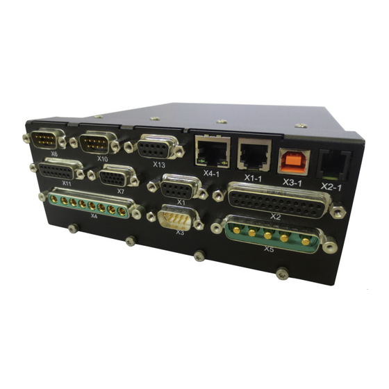
Page 34: Swm7S-150: Connector Assignment
User Manual 5 Electrical Installation SWM7S-150: Connector Assignment Figure 13: SWM7S-150: Connector Assignment MAC-SWM7-UMN-prel-R03b-19 PRELIMINARY... -
Page 35: Swm7-150 With Extended I/Os: Connector Assignment
User Manual 5 Electrical Installation SWM7-150 with extended I/Os: Connector Assignment Figure 14: SWM7-150 with extended I/Os: Connector Assignment MAC-SWM7-UMN-prel-R03b-19 PRELIMINARY... -
Page 36: Swm7-48/100: Connector Assignment
User Manual 5 Electrical Installation SWM7-48/100: Connector Assignment Figure 15: SWM7-48/100: Connector Assignment MAC-SWM7-UMN-prel-R03b-19 PRELIMINARY... -
Page 37: Swm7-300/600: Connector Assignment
User Manual 5 Electrical Installation SWM7-300, SWM7-600: Connector Assignment Figure 16: SWM7-300, -600: Connector Assignment MAC-SWM7-UMN-prel-R03b-19 PRELIMINARY... -
Page 38: Power Supply
User Manual 5 Electrical Installation Power Supply Different members of the SWM family have different auxiliary and DC-link supply voltages, cur- rents and connections. Please refer for detailed information to the datasheet of the specific de- vice. Important notes for the DC-link- and the auxiliary power supply can be found under 5.1 Safety In- structions and 5.2 Installation Instructions. -
Page 39: Enable Interface (X1-1)
User Manual 5 Electrical Installation 5.10 Enable Interface (X1-1) A hardware (HW) enable signal is not necessarily needed. The HW enable signal can be disabled in the “COMMAND INPUT SELECT” tab to “none used” or enabled to different signal input op- tions. -
Page 40: Command Interface (X2)
User Manual 5 Electrical Installation 5.11 Command Interface (X2) The command interface on X2 includes two differential analog inputs and three analog outputs with +/-10V signal voltage range. The analog inputs can be used to include the SWM into a sys- tem with complete analog signal environment. -
Page 41: Digital Inputs
User Manual 5 Electrical Installation 5.11.3 Digital Inputs ● 2 digital galvanically isolated inputs (DIGIN1, 2) ● Input level (nom.) +5V ● Input level (max.) +24V ● Vil max. = 1V ● Vih min. = 2.5V ● Input resistance 4 kOhm (Pull-Down) ●... -
Page 42: Encoder Outputs
User Manual 5 Electrical Installation 5.11.5 Encoder Outputs ● 3 differential encoder outputs ● Reference is DGND (available at X2-12) Signal Description A_Out X2-3 Output A / A_Out X2-4 Inverting Output A B_Out X2-5 Output B / B_Out X2-6 Inverting Output B Z_Out X2-7 Output Z... -
Page 43: Optoisolated I/O - Port (X7)
User Manual 5 Electrical Installation 5.12 Optoisolated I/O - Port (X7) Additional to the isolated digital I/O signals with fix functionality from X2, connector X7 provides additional 3 digital inputs and 3 additional digital outputs free programmable for customer use. The digital inputs from X2, digital outputs from X2, digital inputs from X7 and digital outputs from X7 use a common ground, which is isolated from the internal controller ground, the DIGIN- GND/DIGOUT-GND. -
Page 44: Relay" Outputs
User Manual 5 Electrical Installation Connection front Hints DIGOUT4 X7-7 can be configured for customer purposes DIGOUT5 X7-8 DIGOUT6 X7-9 Tab. 5.5: SWM7 Digital Outputs on X7 5.12.3 “Relay” Outputs ● Compared to the real relay contact of the SWM6, the SWM7 uses solid state AC pho- tomos coupler outputs. -
Page 45: Motor Power Connector (X4)
User Manual 5 Electrical Installation 5.13 Motor Power Connector (X4) The SWM drives are extreme flexible devices. They are prepared to drive many different types of motors to cover most applications within their power range. The examples show connection of a three phase motor and a single phase motor. A two phase motor is connected by connecting first motor phase to controller phase U, second motor phase to controller phase V and the common of both motor phases to controller phase W. -
Page 46: Mechanical Brake (X3)
User Manual 5 Electrical Installation 5.14 Mechanical Brake (X3) Please refer to chapter 5.1 Safety Instructions when active electrical braking is required! Please note that the mechanical brake circuitry is not functional save accord- ing to the definitions of the DIN ISO standards and must not be used for safety critical applications. -
Page 47: Feedback Sensors
User Manual 5 Electrical Installation 5.15 Feedback Sensors Every closed servo system will normally require at least one mechanical feedback device for sending actual values from the motor to the servo drive. Depending on the type of feedback-sen- sor, the controller can regulate on speed or on position. If a position sensor is used, the drive can be configured to position control or speed control. -
Page 48: Dc Tachometer (X13)
User Manual 5 Electrical Installation To ensure a smooth start of a motor with hall effect sensors, the position of the sensors must be accurately aligned to the electrical position of the motor. Inaccurate mounting of the sensors also can also result in wrong signals at high motor currents or at high motor speed. -
Page 49: Resolver (X9)
User Manual 5 Electrical Installation 5.18 (X9) Resolver The resolver is a robust commutation and position feedback device with medium accuracy. The SWM servo controller allows connection of a 2-pole or a multi-pole resolver. The resolver excitation voltage is fix, 20Vpp. Maximum resolver excitation current is 75mA peak. -
Page 50: Digital Encoder (X6)
User Manual 5 Electrical Installation 5.19 (X6) Digital Encoder The encoder is a digital feedback system which can have very high resolutions. Low encoder res- olutions are 500 to 1000 lines, but encoders can have up to 18000 lines resolution. There are incremental encoders with or without index pulse available, as well as absolute en- coders for single- and multi turn. -
Page 51: Sin/Cos Encoder (X11)
User Manual 5 Electrical Installation Figure 27: Encoder: Single-Ended Signals (TTL) 5.20 SIN/COS Encoder (X11) Connector X11 provides a complex sensor interface with two differential analog 1Vss inputs for sin and cos signal, two differential digital RS422 inputs and a 5V sensor supply. This allows con- nection of different types of sensors from a simple analog sin/cos encoder over a complex EnDat 2.2 up to a Netzer encoder. -
Page 52: Sine Encoder With Endat 2.2 (X11)
User Manual 5 Electrical Installation 5.21 Sine Encoder with EnDat 2.2 (X11) The sine encoder with ENDAT interface provides a mixture of differential analog sin/cos signals in combination with differential digital signals. The SWM7/LWM7 fetches the position data at a rate of 10 and 20 kHz. Reading will be done with 2 MHz. -
Page 53: Netzer Encoder (X11)
User Manual 5 Electrical Installation 5.22 Netzer Encoder (X11) The Netzer encoder uses a capacitive measuring principle and provides analog output signals. Figure 30: Netzer Encoder 5.23 Encoder with BiSS/SSI (X11) The BISS encoder uses the only the pure digital interface portion of X11 and the sensor supply. The SWM7 supports BISS-C (no safety), but without line delay compensation for long bus lines. -
Page 54: Amr-Encoder (X11)
User Manual 5 Electrical Installation 5.24 AMR-Encoder (X11) An AMR encoder works on the base of the anisotrop magneto resistive effect. It is chosen as ex- ample for connection of an analog signal sensor with single-ended sin and cos signal. For connection of single ended signals, the AMR-option of the SWM needs to be ordered! With AMR-option, the input voltage range for sin- and cos- to AGND is 2,5V (zero) +/- 1,2V. -
Page 55: Can Interface (X10)
User Manual 5 Electrical Installation 5.26 CAN Interface (X10) The CAN communication profile is a MACCON standard. A customized profile can be provided on request. The graphical user interface provides a separate page for CAN. Parameter setting windows and display windows facilitate set-up and debug of the CAN communication interface. The CAN interface is galvanically isolated. -
Page 56: Emc Considerations
User Manual 6 EMC Considerations EMC Considerations The SWM servo controllers are designed for functional prototypes. They use internal noise reduc- tion technology like most other switching drive controllers, but they are optimized on seize, not on EMC. When these drives should be used in systems with strict and clearly defined DIN ISO EMC standards, additional external filters and grounding and shielding effort might be required. -
Page 57: Tab. 6.2: Motor Chokes (Optional)
User Manual 6 EMC Considerations Differential mode inductors can be used to improve the PWM ripple at low inductance motors. Motor cables are critical for EMC because they are directly connected to the fast switching PWM outputs of the drive controller. Their parasitic capacitance builds a noticeable capacitive load to the output stage of the controller. -
Page 58: Mounting Instructions
User Manual 6 EMC Considerations Mounting Instructions ● A metallic cabinet or enclosure is recommended where large ground contact areas can pro- vide low high frequency impedance for ground connections. ● All siganl cables from and to the SWM7S servo controller need to be shielded. ●... -
Page 59: Setup Tool Swm7.Exe
User Manual 7 SetUp Tool SWM7.exe SetUp Tool SWM7.exe The SWM7 Setup tool provides a PC user interface which can be used for: ● Configuration and parametrization of the SWM ● Monitoring paramertes for observations, bringup and debug ● Customization of the PC user interface as application specific display MACCON offers training courses on request. -
Page 60: Working With The Swm7 Setup Tool
User Manual 7 SetUp Tool SWM7.exe ● Create a working directory on your PC and copy at minimum the “swm7.exe” and the “complete functionality.mac” files from the SWM Software CD into your working directory. The .mac file represents the layout of the user interface and can be customized. ●... -
Page 61: Offline-Operation: Pc Without Connected Drive
User Manual 7 SetUp Tool SWM7.exe 7.3.2 Offline-Operation: PC without Connected Drive Before the physical connection to the SWM is connected, the “swm7.exe” can work offline. In this mode you can prepare the setup of the drive and the graphical user interface: ●... - Page 62 User Manual 7 SetUp Tool SWM7.exe ● Check the RS232 connection between PC and SWM: Data transfer on the RS232 interface can be observed with: Service/Show Communication. It is recommended to spread the “Telegramme” window that wide to see a whole telegram in one line. If the RS232 connection does not work, please check the COM port settings in the setup tool and in your computer like described in the installation chapter.
-
Page 63: Bringup To Full Functional Drive System
User Manual 7 SetUp Tool SWM7.exe 7.3.4 Bringup to Full Functional Drive System Working in ONLINE mode connected to a powered drive, parameters can quickly be changed and tested. This mode is helpful for bringup and tests. ● Ensure that both, auxiliary supply and DC-link supply of the SWM are off. ●... -
Page 64: Tab. 7.2: Typical Measure And Control Windows
User Manual 7 SetUp Tool SWM7.exe Typical Measure and Control Windows Window name Example Remarks Parameter display Using the “+” and “-” keys you can adjust the desired parameter value, even as the sign of the value. Use or no use of parameter “Index Pulse” Measuring display Display “Abs. -
Page 65: Analyzing Parameter Files
User Manual 7 SetUp Tool SWM7.exe 7.3.6 Analyzing Parameter Files Shows the parameter values stored in a *.macp file and allows the export into *.csv or into *.txt file format. ➭ Choose in menu item “File” “Examine Parameter file...”, and select a *.macp file. The result is shown in Fig. -
Page 66: Customization Of The Graphical User Interface
User Manual 7 SetUp Tool SWM7.exe 7.3.7 Customization of the Graphical User Interface 7.3.7.1 Adding Parameter Displays The menu item “Parameters” opens a window which allows selecting additional parameters for display. The window is empty if no SWM is connected or if the connected SWM is unpowered. When the connected SWM is powered, simply move the desired parameter to the certain setup page by drag-and-drop, see below: Figure 42: Example of Adding the Parameter “Profile: Max. -
Page 67: Creating User-Defined Tabs
User Manual 7 SetUp Tool SWM7.exe 7.3.7.3 Creating user-defined Tabs You have the ability to create your own tabs (parameter page(s)) for controlling and monitoring ➭ your drive system. Choose in menu item “Service” “Modify”. Then right-click on a free area in the tool bar to open the context menu, see Fig. 43. Figure 44: "Add Sheet"... -
Page 68: Description Of Menus And Windows
User Manual 7 SetUp Tool SWM7.exe Description of Menus and Windows The menu items are described in the following. You can open the menu items using – the mouse pointer or – <ALT> key followed by the underlined letter e.g. <ALT+f> to open the “File” menu. 7.4.1 File Menu Menu item Description... -
Page 69: Service Menu
User Manual 7 SetUp Tool SWM7.exe 7.4.4 Service Menu Menu item Description <ALT+e> Modify If selected (active) “Modify” it is possible to <ALT+e+m> – change the location of any control element and/or – add additional elements or tab sheets. Save the new settings in your “personnel GUI” layout *.mac file. Go Offline Disables communication (for MACCON technical support.) <ALT+e+o>... -
Page 70: Communication Errors
User Manual 7 SetUp Tool SWM7.exe 7.5.2 RS-232 Communication Errors 7.5.2.1 Message “Transmitting Telegram: No Response” Indicates that the SWM7 unit is not responding. Check power supply, cabling and COM port set- ting. 7.5.2.2 Message “COM Error 0x02” If you use a build-in COM port and frequently get an error message like “COM Error 0x02” in the status line of SWM7 program, it is necessary to change the serial port setting. -
Page 71: Invalid Combination Of Feedback Sensors
User Manual 7 SetUp Tool SWM7.exe 3. Reduce settings for receive buffer to 4. Figure 50: Adjust Receive Buffer for COM Port 4. Click “OK” to close all device manager windows. 5. Restart Windows to make these changes become effective. Now the warnings should not appear any more. -
Page 72: Incomplete Sensor Definitions
User Manual 7 SetUp Tool SWM7.exe 7.5.5 Incomplete Sensor Definitions Some sensors need additional configuration, e. g. if you select “Hall sensors” as feedback sensor you also have to define the hall switch type (supply voltage). Otherwise, an error message is output: Figure 53: Failure “No Hall Sensor Type defined”... -
Page 73: Over Temperature Motor
User Manual 7 SetUp Tool SWM7.exe 7.5.10 Over Temperature Motor This messages indicates, that the motor temperature is above the limit. Figure 55: Failure “Over Temperature Motor” Example: Choice of motor temperature sensors: Currently used, the PTC130°C. 7.5.11 Resolver Error Resolver does not work properly, please check cabling and resolver and settings. -
Page 74: Swm Failure Codes
User Manual 7 SetUp Tool SWM7.exe 7.5.15 SWM Failure Codes The SWM6 and SWM7 have internal failure codes. The SWM6 has 3 Bit and the SWM has 4 Bit failure codes. There are small differences in the failure interpretation of the F0...F2 bit code be- tween SWM6 and SWM7, see table below. -
Page 75: Firmware Update
User Manual 7 SetUp Tool SWM7.exe Firmware Update The SWM7.exe provides a tool for firmware updates. The internal SWM control card is a highly complex digital controller consisting microcontroller, DSP and FPGA. The update can be done ei- ther for the microcontroller, for the DSP or for the FPGA. NEVER do firmware updates without written approval of MACCON for a specific device. -
Page 76: System Parameter Setup
User Manual 8 System Parameter Setup System Parameter Setup This User Manual describes the control tabs and functions of the SWM7.exe and typical applica- tion examples for the SWM7 servo controller family. Pay attention to the Safety Instructions, to avoid any risk for dangerous voltages, temperatures and hardware damage. -
Page 77: Swm7 Control Tabs
User Manual 8 System Parameter Setup SWM7 Control Tabs This chapter describes all control windows of the SWM7.exe: 8.1.2..SWM STATUS..........79 8.1.3..DATA ACQUISITION........81 8.1.4..FIELD WEAKENING........88 8.1.5..OFFSET............94 8.1.6..SYSTEM SETUP...........96 8.1.7..MOTION SENSORS........99 8.1.8..COMMAND INPUT........105 8.1.9..ANALOG INPUT..........108 8.1.10..CAN...............111 8.1.11..SENSORLESS CONTROL......120 8.1.12..PHASE FINDING...........127 8.1.13..POSITION CONTROL........136 –....BackEMF PHASE FINDING......(not described) –....PWM INPUT..........(not described) 8.1.14..MOTION SENSOR MONITORING....140... -
Page 78: Frequently Asked Questions
User Manual 8 System Parameter Setup 8.1.1 Frequently Asked Questions: Question 1: Where do percentage current values refer to? Answer: To nominal current of the device: SWM7-48-100 has 200A nominal (peak-)current. Question 2: Why does a setting jump back to old value, setting of new value is impossible? Answer: SWM needs to be disabled. -
Page 79: Swm Status
User Manual 8 System Parameter Setup 8.1.2 SWM STATUS On this tab, firmware versions and internal status flags are displayed. This information might be required for MACCON technical support. Figure 57: STATUS Tab MAC-SWM7-UMN-prel-R03b-19 PRELIMINARY... - Page 80 User Manual 8 System Parameter Setup Control Windows in the "SWM STATUS" Tab Control window Explanation SWM STATUS (in alphabetic order) Input values DSP CPU load Display percentage DSP processing load. For MACCON tech assistance only. DSP Error Flags (live) Displays the DSP error flags.
-
Page 81: Data Acquisition
User Manual 8 System Parameter Setup Control window Explanation SWM STATUS (in alphabetic order) Input values STR Error Flags (live) Displays the µC flags. STR710 CPU load Display percentage of µC load. For MACCON tech assistance only. Tab. 8.1: Control Windows in the "SWM STATUS" Tab 8.1.3 DATA ACQUISITION The “DATA ACQUISITION”... - Page 82 User Manual 8 System Parameter Setup Internal Debug-Variables: <Digital Out (DSP)>: • OUT1..OUT8: Digital-outputs of SWMs, controlled from internal <Digital Out (STR)>: • OUT1..OUT8: Digital-outputs of SWMs, controlled from internal mi- crocontroller • mux1..mux8: If active, the microcontroller controls the state of the outputs.
- Page 83 User Manual 8 System Parameter Setup Control Windows in the "DATA ACQUISITION" Tab Control window Explanation DATA ACQUISITION (in alphabetic order) Input values ANAOUT1 Gain Gain for analog output #1 Gain 1.0 outputs – -10 V...+10 V or – 0...+5 V * for signal values of -1.0 ...
- Page 84 User Manual 8 System Parameter Setup Control window Explanation DATA ACQUISITION (in alphabetic order) Input values ANAOUT2 Offset Offset adjust of analog output #2 ANAOUT3 Gain Gain adjust of analog output #3 see “ANAOUT1 Gain” ANAOUT3 Offset Offset adjust of analog output #3 ANAOUT3-6 Voltage Range Voltage range selection for analog output #3 - #6.
- Page 85 User Manual 8 System Parameter Setup Control window Explanation DATA ACQUISITION (in alphabetic order) Input values Bus Current ADC Range Sets the scaling for ADC converter. This value is constant for each device and must not be changed by the user. Change only when asked by MACCON technical support.
- Page 86 User Manual 8 System Parameter Setup Control window Explanation DATA ACQUISITION (in alphabetic order) Input values Digital In Status display of digital inputs. For customer specific applications only. Digital Out (DSP) Status display of digital outputs as commanded by DSP. For MACCON tech assistance only.
-
Page 87: Tab. 8.2: Control Windows In The "Data Acquisition" Tab
User Manual 8 System Parameter Setup Control window Explanation DATA ACQUISITION (in alphabetic order) Input values FPGA Status Flags 2 Displays state of brake. Max. Bus Voltage DC bus voltage limit for generating over-voltage error. Standard value: 80 Volt for 48 V units Motor Temperature Actual motor temperature in °C. -
Page 88: Field Weakening
User Manual 8 System Parameter Setup 8.1.4 FIELD WEAKENING Field weakening can be used to drive a motor at a higher speed than nominal for a given DC sup- ply voltage with reduced torque. The field weakening effect is achieved by influencing the ID and IQ current vectors. The current control mode of the SWM needs to be configured as “Field Orientated”, of course. - Page 89 User Manual 8 System Parameter Setup Setting only an effective current vector I , the reaction is an output voltage of U1. If this voltage increases the bus voltage, no further current can be supplied and the motor speed reaches its limit.
- Page 90 User Manual 8 System Parameter Setup Normal application of field weakening is to set Id and Iq via CAN in current control mode. This is often used in motor test applications. Second proven application is the field weakening mode “AnaIN2→Angle”. Caution: The “Speed→Angle”...
- Page 91 User Manual 8 System Parameter Setup The Phase Angle Adjust at zero speed can be used to utilize reluctance effects. Figure 64: FIELD WEAKENING Tab MAC-SWM7-UMN-prel-R03b-19 PRELIMINARY...
- Page 92 User Manual 8 System Parameter Setup Control Windows in the "FIELD WEAKENING" Tab Control window Explanation FIELD WEAKENING (in alphabetic order) Input values Current Command D Command Value for D Current Current Command Q Command Value for Q Current Current Command D Display for actual current loop command (D vector) D vector resulting from speed...
-
Page 93: Tab. 8.3: Control Windows In The "Field Weakening" Tab
User Manual 8 System Parameter Setup Control window Explanation FIELD WEAKENING (in alphabetic order) Input values Field weakening mode selection. IQ=const: IQ=commanded current, ID is set by algorithm Imot=const: current magnitude = commanded current; ratio between IQ and ID set by algorithm Max. -
Page 94: Offset
User Manual 8 System Parameter Setup 8.1.5 OFFSET The “OFFSET” tab allows manual offset calibration of the analogue inputs, the phase currents and the DC tachometer input. Figure 65: OFFSET Tab Pay attention to Phase Curr. Offset U and V: These Parameters only can changed at enabled drive. -
Page 95: Tab. 8.4: Control Windows In The Offset Tab
User Manual 8 System Parameter Setup Control window Explanation OFFSET (in alphabetic order) Input values Analog-In 1 Offset Offset adjust of analog input #1 Standard: 0 Analog-In 2 Offset Offset adjust of analog input #2 Standard: 0 DC Tach Input Actual value of DC tachometer input Range -32768 to +32767... -
Page 96: System Setup
User Manual 8 System Parameter Setup 8.1.6 SYSTEM SETUP The “SYSTEM SETUP” tab is very important because it defines the properties of the motor and the switching frequency of the SWM. Also temperature limits can be defined and temperatures can be measured. Before setup check the connected hardware (motor data sheet, sensor type). - Page 97 User Manual 8 System Parameter Setup Control Windows in the "SYSTEM SETUP" Tab Control window Explanation SYSTEM SETUP (in alphabetic order) Input values Back EMF Const EMF constant of single phase circuit. The EMF value measured between two motor phases (RMS) has to be √...
-
Page 98: Tab. 8.5: Control Windows In The "System Setup" Tab
User Manual 8 System Parameter Setup Control window Explanation SYSTEM SETUP (in alphabetic order) Input values Pole Pairs Selection of number of motor pole- pairs Only for rotary motors. Pole Pitch Motor Type = Linear Selection of pole pitch for linear motor Only for linear motors. -
Page 99: Motion Sensors
User Manual 8 System Parameter Setup 8.1.7 MOTION SENSORS The “MOTION SENSORS” tab is used to define the settings for the chosen feedback sensor. Figure 67: MOTION SENSORS Tab Encoder EXE = TTL encoder emulation, indicates actual position of commutation sensor. This can be each position sensor except a Hall sensor. - Page 100 User Manual 8 System Parameter Setup HALL The SWM has an implemented position estimating algorithm when only hall sensors are avail- able. This works better for higher speed, for lower speed it has some limitations. <MaxHallTimeMS>: Largest Hall period time (= lowest speed), for functional Hall ob- server to interpolate the position.
- Page 101 User Manual 8 System Parameter Setup Control Windows in the "MOTION SENSORS" Tab Control window Explanation MOTION SENSORS (in alphabetic order) Input values DC Tach Full Scale Speed DC tachometer scaling range DC Tach Input Actual value of DC tachometer input. Range -32768 to +32767 DC Tach Offset DC tachometer input offset adjust...
- Page 102 User Manual 8 System Parameter Setup Control window Explanation MOTION SENSORS (in alphabetic order) Input values Hall Phases Hall sensor configuration: 3 Phases: Using 3 hall sensors with 120 degree spacing 2 Phases: Using 3 hall sensors with 120 degree spacing 12 Steps: for special use only Hall sensor type Supply voltage of connected hall...
- Page 103 User Manual 8 System Parameter Setup Control window Explanation MOTION SENSORS (in alphabetic order) Input values Netzer Coarse/Fine Shift Phase shift between coarse and fine track. Result of auto offset compen- sation, can be adjusted manually. Used by MACCON technical support.
-
Page 104: Tab. 8.6: Control Windows In The "Motion Sensors" Tab
User Manual 8 System Parameter Setup Control window Explanation MOTION SENSORS (in alphabetic order) Input values Sine Enc2 Amplitude Amplitude of sine encoder 2 or resolver Used by MACCON technical support. Use DC Tach Indicates DC tachometer as selected feedback sensor Display only. -
Page 105: Command Input
User Manual 8 System Parameter Setup 8.1.8 COMMAND INPUT This section defines the command source for the SWM drive. The drive can be controlled via this tab on the PC, CAN or analog or PWM hardware inputs. Figure 68: COMMAND INPUT Tab Control Windows in the "COMMAND INPUT SELECT"... - Page 106 User Manual 8 System Parameter Setup Control window Explanation COMMAND INPUT SELECT (in alphabetic order) Input values CAN Enable Request Status of CAN Enable request. Usage depends on CAN firmware Command Input Selection of desired command channel for operation. Use “Analog” when connecting an external function generator.
-
Page 107: Tab. 8.7: Control Windows In The "Command Input Select" Tab
User Manual 8 System Parameter Setup Control window Explanation COMMAND INPUT SELECT (in alphabetic order) Input values PC: Alt. Speed Command Second speed setpoint Can be used for fast switching and generating a step behavior. PC: Current Command Manual current setpoint (Q vector) “Command input”... -
Page 108: Analog Input
User Manual 8 System Parameter Setup ANALOG INPUT 8.1.9 The "ANALOG INPUT" tab configures offset, gain and scaling of the analog inputs. Figure 69: ANALOG INPUT Tab Control Windows in the "ANALOG INPUT" Tab Control window Explanation ANALOG INPUT (in alphabetic order) Input values Analog Cmd Input 1 Analog Input #1 Command Value... - Page 109 User Manual 8 System Parameter Setup Control window Explanation ANALOG INPUT (in alphabetic order) Input values Analog Cmd1 Adjusted Scaled value of analog command input signal #1 Analog Cmd1: Gain Adjust Gain adjust for analog command input signal #1 Analog Cmd2 Adjusted Scaled value of analog command input signal #2 Analog Cmd2: Gain Adjust...
-
Page 110: Tab. 8.8: Control Windows In The "Analog Input" Tab
User Manual 8 System Parameter Setup Control window Explanation ANALOG INPUT (in alphabetic order) Input values Analog/PWM: Full Scale Speed Full scale definition of speed command for digital (PWM) or analog command input Invert Command (IQ, Speed, U/V) Inverts the command channel 1 Do not use at enabled drive! Invert Command 2 (ID) Inverts the command channel #2... -
Page 111: Can
User Manual 8 System Parameter Setup 8.1.10 In general, compared to a standard SWM without CAN, the customer needs to purchase the CAN activation if CAN communication is required. This includes the standard CAN protocol of the SWM which is described later. If the customer needs a custom protocol, this can be programmed but needs a separate contract. -
Page 112: Tab. 8.9: Can Telegram 1 From Swm To Host
User Manual 8 System Parameter Setup <CAN Type>: CAN-adress-type of the telegram: Number and content of the CAN- telegrams are custom/firmware specific. <Transmit ID 1> : CAN-Identifier transmit telegram 1 (SWM to Host) <Transmit ID 2> : CAN-Identifier transmit telegram 2 (SWM to Host) <Transmit ID 3>... -
Page 113: Error Codes
User Manual 8 System Parameter Setup Error-Codes: Value Status Value Status 000 OK, no fault 100 Overtemperature heatsink 001 Overvoltage 101 Error Resolver-/Encoder 010 Undervoltage 110 I2t warning 011 Overcurrent 111 I t Error Tab. 8.11: Device Failure-Codes in CAN-Protocol Telegram 1 from Host to SWM (8 Byte): Parameter Desired Value:... - Page 114 User Manual 8 System Parameter Setup CAN Protocol “Standard 1.2”: This is an extended CAN protocol which can be requested without extra charge. CAN-Baud rate: User-programmable via Timing-Parameter CAN-ID's: User-programmable, 11 or 29 Bit Byte order: Intel Format Repetition rate: User-programmable: 1ms ... 100ms Telegram 1 from SWM to Host Control: Telegram Structure: Length 8 Byte actual position (selected position sensor)
- Page 115 User Manual 8 System Parameter Setup Telegram 3 from SWM to Host Control: Telegram structure: Length 8 Byte Motor Temperature SWM Temperature Bus voltage Bus current DIG_IN Status HS_IN Status Brake Status Counter U_BUS I_BUS TEMP_MOTOR ST_DIG_INX ST_HS_INX ST_BRAKE ZAEHLER TEMP_SWM 16 Bit 16 Bit...
- Page 116 User Manual 8 System Parameter Setup Telegram 2 from Host to SWM: Telegram format: Length 8 Byte current command Iq current command Id commutation angle (manual) enable commutation angle setting Iq_SET Id_SET COMM_ANGLE_SET ENAB_COMM_ANGLE_SET Set current command Iq Set current command Id Set commutation angle Enabling to set commutation angle 16 Bit...
- Page 117 User Manual 8 System Parameter Setup Control Windows in the “CAN” Tab Control window Explanation (in alphabetic order) Input values Bit timing prescaler Prescaler for achieving baud rate see below “Bit timing T1, T2” Bit timing T1 CAN Baud rate setting Initial Values T1 = 4, change prescaler for achieving correct baud rate.
- Page 118 User Manual 8 System Parameter Setup Control window Explanation (in alphabetic order) Input values CAN: Act. Position Scaling CAN: commanded value Display of commanded setpoint (dependent on current or speed control mode) for CAN operation CAN: commanded value 2 Display of commanded setpoint (dependent on current or speed control mode) for CAN operation CAN: Max.
-
Page 119: Tab. 8.13: Control Windows In The Can Tab
User Manual 8 System Parameter Setup Control window Explanation (in alphabetic order) Input values Transmit ID 1 CAN identifiers for transmit and receive telegrams have to be set corresponding to master controller. Transmit ID 2 CAN identifiers for transmit and receive telegrams have to be set corresponding to master controller. -
Page 120: Sensorless Control
User Manual 8 System Parameter Setup 8.1.11 SENSORLESS CONTROL Sensorless control is not useful for all applications, it has some limitations. It might work in appli- cations with constant mechanical load, preferable with small speed variation requirements. If a customer considers the use of sensorless control, it is strongly recommended to contact MACCON technical support, provide detailed application description including load profile and motor datasheet, that MACCON can decide if sensorless control is feasable in the specific re- quested application. -
Page 121: Start Sequence
User Manual 8 System Parameter Setup Start-Sequence: The start sequence is the same for both operating modes. It includes three functional steps: DC-Current Motor Alignment: The motor shaft will be aligned with DC-current. A from zero rising current will be driven. The current rises within a programmed <RampTime> to a current value of <Start Current(DC)>. -
Page 122: Motor Model
User Manual 8 System Parameter Setup Motor Model: The behavior of a standard motor model can be visualized with pointer diagrams: The motor inductance causes a phase shift If the estimated mechanical angle does not between motor current and terminal voltage. fit to the actual position (Iq not in phase with induced voltage called Polradspannung), the angle (blue) between current and voltage... - Page 123 User Manual 8 System Parameter Setup Sensorless Controller The deviation between internal and calculated motor position is input for three partial con- trollers which influence the commutation angle, commutation frequency and the amplitude of the motor current. This results in a corrected motor position via PI-controller. The <Phase Adjust Gain> parame- ters can be programmed separately for the three functional phases DC Alignment, uncontrolled Ramp and for the regulated state.
- Page 124 User Manual 8 System Parameter Setup Control Windows in the "SENSORLESS CONTROL” Tab Control window Explanation SENSORLESS CONTROL (in alphabetic order) Input values Acceleration Speed ramp for closed loop continuation of speed ramp. Acceleration uncontrolled Speed ramp for open-loop startup. Alignment Delay Time for changing parameters from open to closed loop control.
- Page 125 User Manual 8 System Parameter Setup Control window Explanation SENSORLESS CONTROL (in alphabetic order) Input values Max. uncontrolled Speed Maximum speed for open-loop startup. Minimal Current Set the minimal current. Setting for sensorless control. Observer Low Pass Logarithmic setting of position observer gain.
-
Page 126: Tab. 8.14: Control Windows In The "Sensorless Control" Tab
User Manual 8 System Parameter Setup Control window Explanation SENSORLESS CONTROL (in alphabetic order) Input values S/L Phase Angle Error Monitoring values for optimizing sensorless control. S/L Phase Correction Monitoring values for optimizing sensorless control. Start Current (DC) Initial current for motor alignment Suggested start value 5 % Tab. -
Page 127: Phase Finding
User Manual 8 System Parameter Setup 8.1.12 PHASE FINDING Before running the “PHASE-FINDING” function please make sure that the motor is unloaded and that the current control loop has been tuned like described in chapter 8.3 Current Control Loop. Phase finding does not work in current control mode because current con- trol mode works without sensor signal. - Page 128 User Manual 8 System Parameter Setup Investigation of the actual motor position is done in two steps: At first, the actual measured position from the feedback sensor will be stored. Coarse Tuning The controller applies equally distributed space current vectors V1...V5 to the motor and senses the shaft acceleration for each vector.
- Page 129 User Manual 8 System Parameter Setup Parameters The Convergence Quality should be more than 90%. The Convergence Error should be lower than 10%. The shake amplitude should be smaller than 5°el. The ideal result of the phase finding procedure in the “PHASE FINDING” tab looks like: If the “PHASE-FINDING”...
- Page 130 User Manual 8 System Parameter Setup Inverting of the sensor signals: Please ensure that the drive is disabled. Go to the “SPEED / CURRENT CONTROL” tab and in- vert the commutation sensor signal and additionally the speed sensor signal and the position sensor signal: Make sure that in the same tab the following settings for the phase finding are checked.
-
Page 131: Digital Inputs
User Manual 8 System Parameter Setup Control via Graphical User Interface Command: Enable Phase-Finding („Busy“ = yellow Drive the motor with external load machine at useful speed („Min.Speed reached“ = green) Click „Capture“ to save the voltage angle („CW Angle Captured“ = grün) Drive the motor with external load machine at same speed in reverse direction Click „Capture“... - Page 132 User Manual 8 System Parameter Setup Telegram 2 from Host to SWM: • Byte 7 Bit 0: Run • Byte 7 Bit 1: Capture • Byte 7 Bit 2: Copy Commutation Angle Telegram 2 from SWM to Host • Byte 7 Bit 0: Busy •...
- Page 133 User Manual 8 System Parameter Setup Phase Finding Control via PC (Graphical User Interface): Status-Flags: Calculated Values: MAC-SWM7-UMN-prel-R03b-19 PRELIMINARY...
- Page 134 User Manual 8 System Parameter Setup Control Windows in the "PHASE FINDING" Tab Control window Explanation Phase Finding (in alphabetic order) Input values Coarse Tuning Gain Amplitude for coarse tuning cycle. Coarse Tuning Time Suggested start value: 1000 ms Communication angle (manual) Can be adjusted manually for special requirements Is set automatically from the...
-
Page 135: Tab. 8.15: Control Windows In The "Phase Finding" Tab
User Manual 8 System Parameter Setup Control window Explanation Phase Finding (in alphabetic order) Input values Motor Startup Synchronization The “Phase Finding” is used to align sensor and motor position for absolute feedback sensors like absolute encoders or resolvers. It can also be used for After first enabling, the phase incremental encoders, but not for finding result can be used until... -
Page 136: Position Control
User Manual 8 System Parameter Setup 8.1.13 POSITION CONTROL The "POSITION CONTROL” tab includes settings and parameter displays for the position sen- sors and for position control mode. Figure 76: POSITION CONTROL Tab Control Windows in the "POSITION CONTROL” tab Control window Explanation POSITION CONTROL... - Page 137 User Manual 8 System Parameter Setup Control window Explanation POSITION CONTROL (in alphabetic order) Input values Index Position Displays the index position None Index Pulse Selection of “Use Index Pulse” for commutation Choose Use or not used Internal Target Position Displays the internal target position of profile generator None...
- Page 138 User Manual 8 System Parameter Setup Control window Explanation POSITION CONTROL (in alphabetic order) Input values Position Control: Speed Command Speed command resulting from position profile generator Position Sensor Select Defines the type of position feedback sensor Display only Profile State State of profile generator Display only Profile: Max.
-
Page 139: Tab. 8.16: Control Windows In The "Position Control" Tab
User Manual 8 System Parameter Setup Control window Explanation POSITION CONTROL (in alphabetic order) Input values Target Position Target position of the profile generator Use Index Pulse Displays state of index pulse. Displays Index Pulse Used, if “Use Index Pulse” was selected. Tab. -
Page 140: Motion Sensor Monitoring
User Manual 8 System Parameter Setup 8.1.14 MOTION SENSOR MONITORING The "MOTION SENSOR MONITORING” tab includes settings and parameter displays for the mo- tion sensors and for speed control mode. For sinusoidal encoders, an automatic offset compensation routine is available. The compensa- tion values can be adjusted manually. - Page 141 User Manual 8 System Parameter Setup Control Windows in the "MOTION SENSOR MONITORING" Tab Control window Explanation MOTION SENSOR MONITORING (in alphabetic order) Input values Dig. Encoder State Indicates initialized sensor Display only EnDat Multi Turns Multi-turns of connected EnDat position sensor, read from sensor Similar to electronic data sheet EnDat Sensor Type...
- Page 142 User Manual 8 System Parameter Setup Control window Explanation MOTION SENSOR MONITORING (in alphabetic order) Input values Sine Enc.2 / Resolver offset comp. (cos) Offset compensation value for cosine channel of sine encoder 2 (or resolver). Set by auto compensation algorithm, can also be adjusted manually.
- Page 143 User Manual 8 System Parameter Setup Control window Explanation MOTION SENSOR MONITORING (in alphabetic order) Input values Sine encoder 1 offset comp. (sin) Offset compensation sine channel of sine encoder #1 Set by auto compensation algorithm. Can also be adjusted manually. Sine encoder 1 offset comp.
- Page 144 User Manual 8 System Parameter Setup Control window Explanation MOTION SENSOR MONITORING (in alphabetic order) Input values SinEnc1 Offset B Offset compensation cosine channel of sine encoder #1 Set by software. Use “Sine encoder 1 offset comp. (cos)” to manually adjust offset. SinEnc1 Phase Actual electrical angle of sine encoder 1 sin/cos signals.
-
Page 145: Tab. 8.17: Control Windows In The "Motion Sensor Monitoring" Tab
User Manual 8 System Parameter Setup Control window Explanation MOTION SENSOR MONITORING (in alphabetic order) Input values SinEnc2 Voltage A Analog voltage of sine channel of sine encoder #2 (or resolver) Range -32768 to +32767 SinEnc2 Min. Volt. B Negative peak voltage of cosine signal of sine encoder #2 (or resolver) Range -32768 to +32767... -
Page 146: Speed / Current Control
User Manual 8 System Parameter Setup 8.1.15 SPEED / CURRENT CONTROL The SWM drive, of course, provides the well known standard cascaded controller architecture of current control loop as inner loop and the speed control loop as outer control loop. The "SPEED / CURRENT CONTROL"... -
Page 147: Tab. 8.18: Lowpass Configuration Values For Resolver Operation
User Manual 8 System Parameter Setup Setting the Feedback Sensor Input Filters Resolver: Tach Lowpass, MAF (Moving Average Lowpass Filter) Sets number of taps (and cut-off frequency) of the moving-average lowpass for speed sensors (not effective for hall sensors or DC tach). In case of resolver operation the lowpass has to be configured according to the Tab. - Page 148 User Manual 8 System Parameter Setup Control Windows in the "SPEED / CURRENT CONTROL" Tab Control window Explanation SPEED / CURRENT CONTROL (in alphabetic order) Input values Commutation Sensor Select Defines the feedback system which is used for commutation In most cases, the commutation sensor is the same as for speed or position, because normally only one senor is mounted at the motor...
- Page 149 User Manual 8 System Parameter Setup Control window Explanation SPEED / CURRENT CONTROL (in alphabetic order) Input values Current Control: P gain P gain adjust of current controller Direction Direction setting for commutation sensor, depending on which side of the motor the commutation sensor is mounted I*t Current Limit I✶t monitoring limit for creating a...
- Page 150 User Manual 8 System Parameter Setup Control window Explanation SPEED / CURRENT CONTROL (in alphabetic order) Input values Phase Curr. P Gain (fast) Fast phase current controller, used in parallel to the slower field-oriented controller, to increase loop bandwidth Position Sensor Select Defines the feedback system which is used for position control loop Rotatory Speed...
- Page 151 User Manual 8 System Parameter Setup Control window Explanation SPEED / CURRENT CONTROL (in alphabetic order) Input values Speed Control: KVFR Speed control feed forward for faster reaction of speed controller. Speed Control: P gain P gain adjust of speed controller Speed Limit Speed limit in current control mode Useful for protection during bring-up...
-
Page 152: Tab. 8.19: Control Windows In The "Speed / Current Control" Tab
User Manual 8 System Parameter Setup Control window Explanation SPEED / CURRENT CONTROL (in alphabetic order) Input values Deceleration limit for speed control mode. (If enabled; see parameter “Speed: Ramp”). Reduces the slope of the speed command if necessary Useful for protection during bring-up Tach Lowpass, MAF For resolver operation. -
Page 153: Control-Structures
User Manual 8 System Parameter Setup Control-Structures The SWM contains multiple control loops interfering with each other. This chapter provides an overview of the internal structure and their parameters, which are accessible from the PC control interface. Figure 80: Overall Control Structure Normalizing of the internal Current: The internal current value I[intern] can vary between -1 and +1. - Page 154 User Manual 8 System Parameter Setup Conventional Current Control Figure 81: Block Diagram: Conventional Current Control In conventional current control mode, the SWM has one current control loop per motor phase. The calculation frequency equals the ADC sampling frequency for the current signals, which is dependent on the programmed PWM frequency.
-
Page 155: Current Control Loop
User Manual 8 System Parameter Setup Current Control Loop An optimum matching of the current controller to the electrical time constants of the motor en- sures accurate torque control and dynamic response. The electric time constant of a motor is the inductance of the winding. This is a first order system which cannot oscillate itself. - Page 156 User Manual 8 System Parameter Setup None of these parameters in the “ANALOG INPUT” tab must be zero. Apply the +/-1V rectangle voltage to “ANALOG COMMAND 1 IN”: For SWM7S and SWM7-300/600 types on connector X2: Pin 16 is signal input, pin 18 is the ground.
- Page 157 User Manual 8 System Parameter Setup The settings for the current controller can be found in the “SPEED / CURRENT CONTROL” tab. Set the I-gain and the D-gain to zero. P gain also remains zero, only P-gain-fast will be set. Set the P-gain-fast to a very high value, e.g.
- Page 158 User Manual 8 System Parameter Setup Figure 84: Setting Current Controller I-Gain: Rectangle Stimulus and CtrlOutD, I-Gain is zero When the I-gain is zero, the CtrlOutD signal is a DC-signal. The offset of the CtrlOutD can be anywhere, mostly negative. Adding carefully I-gain will cause smooth AC portion of the CtrlOutD.
- Page 159 User Manual 8 System Parameter Setup Increasing the I-gain shapes the AC-portion more to rectangle shape and shifts the offset. Figure 86: Setting Current Controller I-Gain: Rectangle Stimulus and CtrlOutD, I-Gain too small (2) Further increasing the I-gain approaches the flat parts of the AC-portion to the zero-line. Figure 87: Setting Current Controller I-Gain: Rectangle Stimulus and CtrlOutD, I-Gain too small (3) MAC-SWM7-UMN-prel-R03b-19 PRELIMINARY...
- Page 160 User Manual 8 System Parameter Setup Further increasing the I-gain brings both flat parts of the AC-portion to the zero-line. That moment when both flat parts reach the zero line represents the perfect I-gain. Figure 88: Setting Current Controller I-Gain: Rectangle Stimulus and CtrlOutD, I-Gain Perfect Adding more I-gain would increase the pulses and decrease the current controller adjustment ac- curacy.
-
Page 161: Speed Control Loop
User Manual 8 System Parameter Setup Speed Control Loop The speed control loop includes the time constant till the motor reaches the desired speed. As- suming a well tuned current control loop, the speed control is a first order system which can be compensated with a PI controller, similar to the current control loop. - Page 162 User Manual 8 System Parameter Setup Set the voltage range to +/-10V and define offset and gain of the analog output. Be aware that signals on analog outputs do not reach the saturation limit, even at overshoots at 50% of expected nominal signal. Run the motor and adapt ANAOUT Gain if necessary.
- Page 163 User Manual 8 System Parameter Setup The P-gain is responsible for the slope. The I-gain is responsible for long term changes. The D-gain can help to reduce oscillations. Increase the P-gain together with the D-gain until the speed ramp does not ramp faster with in- creasing P-gain and the signal does not have oscillations any more.
- Page 164 User Manual 8 System Parameter Setup Figure 90: P-Gain too small: The Acceleration-Slope is too slow. Figure 91: D-Gain too small: Oscillations. MAC-SWM7-UMN-prel-R03b-19 PRELIMINARY...
- Page 165 User Manual 8 System Parameter Setup Figure 92: I-Gain too high: Massive Overshoots Depending on the connected mechanical system, speed controller adjustment is not trivial. The described procedure gives a basic guideline for simple systems, it shows how P, I and D component of the controller act in the drive system.
-
Page 166: Position Control Loop
User Manual 8 System Parameter Setup Position Control Loop The position controller has two different modes: For circular and for linear motors. The difference is, that the mode for linear motors applies to an absolute position. The mode for linear motors refers to one revolution of a circular motor and is optimized to find programmed position quick. - Page 167 User Manual 8 System Parameter Setup Figure 93: Position Controller: Position Step Function and Speed Command Response Figure 94: Position Controller Adjust: Position Step Function and no Oscillations on Speed Signal MAC-SWM7-UMN-prel-R03b-19 PRELIMINARY...
- Page 168 User Manual 8 System Parameter Setup Figure 95: Position Controller Adjust: Position Step Function and Oscillations on Speed Signal A movement profile can be programmed in the “POSITION CONTROL” tab defining “Target Posi- tion”, “Position Control: Max. Speed”, “Profile: Max. Speed”, “Profile: Max. Acceleration” and “Profile: Max.
-
Page 169: Pwm Modulation Method
User Manual 8 System Parameter Setup PWM Modulation Method The SWM-family uses center-aligned PWM. One advantage of this method is zero phase voltage ripple and current ripple at modulation points 50% / 50%, 100% / 0% and 0% / 100%. Second advantage is effectively double PWM frequency at phase outputs while all power switches are working at single PWM frequency. -
Page 170: Trouble Shooting
User Manual 8 System Parameter Setup Trouble Shooting Fault Possible causes Measures Wrong cable used Use the original cable delivered together with each SWM Error Message: Wrong PC interface selected Correct COM port settings Communication fault Problems with RS232/USB converter Repeat driver installation procedure of the converter according to the converter manual SWM is still disabled... -
Page 171: Simple Start- Or Debug Applications
User Manual 8 System Parameter Setup Simple Start- or Debug Applications Currents: DC-link, Phase, Measurement To measure the motor current, the SWM provides three physical analog outputs which can be configured for different parameters, e.g. the phase current for the motor. These outputs are fast enough to connect an oscilloscope to measure transients. -
Page 172: Brushed Dc-Motor Direct Current Control
User Manual 8 System Parameter Setup 8.8.1 Brushed DC-Motor Direct Current Control For tests and bringup, a low voltage of the DC-link supply can reduce risks. In this case, increasing the regulated current results in a maximum speed. Further in- crease of current does not further increase in speed, because the programmed DC-link voltage is limiting the speed of the motor. - Page 173 User Manual 8 System Parameter Setup Set the drive mode to Current Control. For save device handling without need of external hardware enable please set: The motor current can be controlled with the following window: MAC-SWM7-UMN-prel-R03b-19 PRELIMINARY...
-
Page 174: Adding A Tachometer Feedback Sensor For Speed Control
User Manual 8 System Parameter Setup 8.8.2 Adding a Tachometer Feedback Sensor for Speed Control In this chapter, the pure basic current control of the motor will be extended to a speed control. As speed sensor, a tachometer is used. After hardware connection of the tachometer, the following settings and changes in the SWM7.exe are required based on the previous pure current control example: SPEED / CURRENT CONTROL tab... - Page 175 User Manual 8 System Parameter Setup COMMAND INPUT SELECT Change the regulation mode from the current control of the previous example to speed control. Please do not change the speed at enabled drive because decreasing the speed causes active braking, so the DC-link voltage source needs to be able to sink energy or a chopper is required in parallel to the source to burn brak- ing energy in a resistor.
-
Page 176: Resolver-Setup
User Manual 8 System Parameter Setup 8.8.3 Resolver-Setup Example is a 3-Phase permanent magnet synchronous machine application. These motors need a position feedback sensor for commutation, even when they run in current control mode. In this example, the position feedback sensor is a resolver, an absolute feedback sensor with the advantage of measuring the absolute position, even after a power cycle. - Page 177 User Manual 8 System Parameter Setup - Set the resolver input signal filter according to the PWM frequency of the SWM: Check the actual PWM frequency in the “SYSTEM SETUP” tab and the actual resolver excitation frequency in the “MOTION SENSORS” tab: Combine both values with table 8.18 to generate the filter setting value in the “SPEED / CUR- RENT CONTROL”...
-
Page 178: Encoder Setup
User Manual 8 System Parameter Setup 8.8.4 Encoder Setup There are much different types of Encoders available. They can be different from: - the physical sensing technology (optical, magnetic, capacitive, …) - the property (relative, absolute, single-turn, multi turn, …) - their interface (single ended TTL, differential, ...) The SWM supports a wide bandwidth of different types from both sides, the hardware interface side and the software parametrization side. - Page 179 User Manual 8 System Parameter Setup A check if the encoder works can be done in the “POSITION CONTROL” tab. Choose the actual sensor as position sensor. Turn the shaft of the motor one turn and read the “Abs. Position”. An encoder with 2048 lines/rev will show 8192 increments per turn.
-
Page 180: Netzer Setup And Calibration
User Manual 8 System Parameter Setup 8.8.5 Netzer Setup and Calibration The basic settings for using a Netzer encoder need to be done in the “SPEED / CURRENT CONTROL” tab: “Commutation Sensor Select” and “Speed Sensor Select” need to be set to “Netzer”. -
Page 181: 3-Phase Permanent Magnet Synchronous Machine
User Manual 8 System Parameter Setup 8.8.6 3-Phase Permanent Magnet Synchronous Machine A permanent magnet synchronous machine (PMSM), connected to an electronic motor con- troller, needs a commutation sensor even when the motor is driven in current control mode only. Based on the previous chapter, the commutation sensor of this example is a resolver. - Page 182 User Manual 8 System Parameter Setup Define in the SPEED / CURRENT CONTROL tab an acceleration ramp. This is very helpful to smooth movements of the motor and to prevent the DC-link power supply to run into current limit at acceleration steps, if a small power supply is used for experiments or bringup: Assuming manual control mode via PC user interface, the “COMMAND INPUT SELECT”...
- Page 183 User Manual 8 System Parameter Setup Now, the settings and calibration procedure for the chosen sensors need to be done: If a resolver is used, please refer to chapter 8.8.3 Resolver-SetupResolver-Setup on page 176. If an encoder is used, please refer to chapter 8.8.4 Encoder Setup on page 178. Please change parameters only when the drive is disabled! Decreasing com- mand parameters at enabled drive might not be possible! Define a slow “PC: Speed Command”...
Need help?
Do you have a question about the SWM7S Series and is the answer not in the manual?
Questions and answers