Sign In
Upload
Manuals
Brands
MACH SYSTEMS Manuals
Recording Equipment
SAE J2716
MACH SYSTEMS SAE J2716 Manuals
Manuals and User Guides for MACH SYSTEMS SAE J2716. We have
1
MACH SYSTEMS SAE J2716 manual available for free PDF download: User Manual
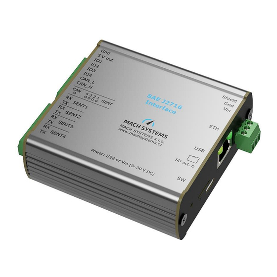
MACH SYSTEMS SAE J2716 User Manual (40 pages)
Brand:
MACH SYSTEMS
| Category:
Recording Equipment
| Size: 2 MB
Table of Contents
Table of Contents
2
About
5
Introduction
5
Figure 1: Front and Rear Sides
5
Features
6
Technical Specification
6
Device Description
7
Overview
7
Power
7
Connectors
7
Figure 2: Top View
7
Table 1: Technical Specification
7
Button
8
Figure 3: Button
8
Table 2: te Connector CN2 Pin Assignment
8
Table 3: SENT Connector Pin Assignment
8
Table 4: Power Connector Pin Assignment
8
Leds
9
Figure 4: Front Side Leds
9
Figure 5: Back Side Leds
9
Table 5: Status Leds on the Front Panel
9
CAN Bus Termination
10
Usb
10
Galvanic Isolation
10
Usage
10
Figure 6: CAN Bus Termination
10
Table 6: Status Leds on the Back Panel
10
Nibble Endianness and Start Bit
11
Website Description
11
Figure 7: Website Header
11
Table 7: Little-Endian Bit Mapping Example
11
Table 8: Big-Endian Bit Mapping Example
11
Figure 8: Device Information
12
Figure 9: RTC Setting
12
Figure 10: RTC Compensation
12
Figure 11: TCP Communication Configuration
13
Figure 12: CAN Configuration
13
Figure 13: SENT Basic Configuration
14
Figure 14: Advanced SENT Configuration
15
Figure 15: SENT/SPC Configuration
15
Table 9: SENT Basic Configuration
15
Table 10: Advanced SENT Configuration
15
Figure 16: Number Format Selection
16
Figure 17: SENT Frame Status
16
Table 11: SENT/SPC Configuration
16
Figure 18: SENT Frame Control
17
Figure 19: I/O Status
18
Figure 20: Analogue Input Configuration
18
Figure 21: Analogue Output Configuration
19
Table 12: Analogue Input Configuration
19
Figure 22: SENT Device Configuration Manipulation
20
Table 13: Analogue Output Configuration
20
Figure 23: SENT Logging Configuration
21
Figure 24: CAN Logging Configuration
21
Table 14: Logging Configuration
21
SAE J2716 Interface Tool
22
Figure 25: Playback Step 1
22
Figure 26: Playback Step 2
22
Figure 27: SAE J2716 Interface Tool Overview
23
Figure 28: Ethernet Connection Parameters
23
Figure 29: USB Connection Parameters
23
Figure 30: CAN Connection Parameters
23
Figure 31: CAN FD Connection Parameters
24
Figure 32: Device Connection
24
Figure 33: Writing Settings to EEPROM
24
Figure 34: Data Trace
24
Figure 35: Slow Data Trace
25
Figure 36: Signal Definition Example
26
Figure 37: Signal Decoding Example
26
Figure 38: Interface Configuration
27
Figure 39: Device Configuration (RTC)
27
Figure 40: Real-Time File Logging
27
SAE J2716 Log Converter
28
SENT/SPC Mode Hardware Changes
28
Figure 41: SAE J2716 Log Converter Overview
28
Hardware Changes for Tick Time under 1 Μs
29
Table 15:Hardware Changes for SENT/SPC
29
Changing the Battery
30
Table 16: Hardware Changes for Tick Time under 1 Μs
30
Firmware Update
31
Figure 42: Screw Removal
31
Figure 43: CR1220 Battery
31
Figure 44: Ethernet Bootloader
32
Delay Measurements
34
SENT to CAN
34
Figure 45: Tdsc Measurement Illustration
34
CAN to SENT
35
SENT to Analogue
35
Figure 46: Tdcs Measurement Illustration
35
Figure 47: Tdsa Measurement Illustration
35
Analogue to SENT
36
Figure 48: Tdas Measurement Illustration
36
Legal Information
37
Usage Warning
37
Disposal and Recycling Information
37
References
38
Ordering Information
39
Table 17: Product Numbers
39
Contact
40
Advertisement
Advertisement
Related Products
MACH SYSTEMS MACH-ETH
MACH SYSTEMS Categories
Recording Equipment
Media Converter
Gateway
USB Interfaces
More MACH SYSTEMS Manuals
Login
Sign In
OR
Sign in with Facebook
Sign in with Google
Upload manual
Upload from disk
Upload from URL