Table of Contents
Advertisement
Quick Links
Changes
Date
Description
15.12.2023 Note about using webserver when SENT Ethernet echo "As
fast as possible" is used
12.12.2023 RTC compensation
25.10.2023 Log Converter, battery change, Windows 7 & 8 USB drivers
20.10.2023 Defined speed class of MicroSD Card for logging
7.9.2023
Draft release
SAE J2716 Interface
User Manual
Author
Review
KH
MM
Advertisement
Table of Contents

Related Manuals for MACH SYSTEMS SAE J2716

Summary of Contents for MACH SYSTEMS SAE J2716
- Page 1 SAE J2716 Interface User Manual Changes Date Description Author Review 15.12.2023 Note about using webserver when SENT Ethernet echo “As fast as possible” is used 12.12.2023 RTC compensation 25.10.2023 Log Converter, battery change, Windows 7 & 8 USB drivers 20.10.2023 Defined speed class of MicroSD Card for logging 7.9.2023...
-
Page 2: Table Of Contents
SAE J2716 Interface - User Manual Contents About ............................5 Introduction ..........................5 Features ............................6 Technical Specification ........................ 6 Device Description ........................7 5.1. Overview ..........................7 5.2. Power ........................... 7 5.3. Connectors .......................... 7 5.4. Button ..........................8 5.5. - Page 3 Figure 24: CAN Logging Configuration ....................21 Figure 25: Playback Step 1 ........................22 Figure 26: Playback Step 2 ........................22 Figure 27: SAE J2716 Interface Tool Overview ..................23 Figure 28: Ethernet Connection Parameters ..................23 Figure 29: USB Connection Parameters ....................23 Figure 30: CAN Connection Parameters ....................
- Page 4 SAE J2716 Interface - User Manual Figure 46: TdCS Measurement Illustration .................... 35 Figure 47: TdSA Measurement Illustration ................... 35 Figure 48: TdAS Measurement Illustration ................... 36 List of Tables Table 1: Technical specification ....................... 7 Table 2: TE Connector CN2 Pin Assignment .................... 8 Table 3: SENT Connector Pin Assignment ....................
-
Page 5: About
2. Introduction The SAE J2716 Interface is a device that acts as a SAE J2716 (SENT bus) gateway for Ethernet, USB, and CAN(/FD). Also, it can realize a USB-CAN(/FD) or Ethernet-CAN(/FD) interface simultaneously to its gateway function. The device offers Ethernet, USB, and CAN(/FD) connection, and uses a standard RJ-45 connector and a USB Type-C connector (virtual serial port - Virtual COM port - VCP). -
Page 6: Features
SAE J2716 Interface - User Manual 3. Features • 4 bi-directional SENT channels o Tick Time 0.5 to 90 µs o Fast frames of up to 8 nibbles • SENT Short PWM Code (SPC) support • Ethernet (10/100) • CAN(/FD) •... -
Page 7: Device Description
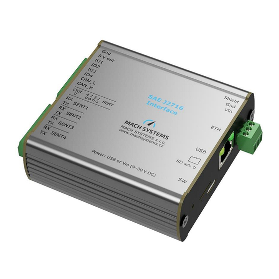
SAE J2716 Interface - User Manual DIN-rail mount (sold separately) Enclosure Aluminium profile Table 1: Technical specification 5. Device Description 5.1. Overview The interface features six connectors, nine LEDs and one push button. Figure 2: Top View 5.2. Power The device can be powered over USB or externally via a 3-pin terminal block. The external power range is 9 –... -
Page 8: Button
SAE J2716 Interface - User Manual CAN_H CAN high Table 2: TE Connector CN2 Pin Assignment Name Description SENT1 RX SENT channel 1 RX SENT1 TX SENT channel 1 TX SENT2 RX SENT channel 2 RX SENT2 TX SENT channel 2 TX... -
Page 9: Leds
SAE J2716 Interface - User Manual 5.5. LEDs The device features 9 LEDs in total. 5.5.1. Front Panel 5 LEDs are on the front side. Figure 4: Front Side LEDs LED Name Note SENT1 Status Off: Channel is stopped SENT2 Status... -
Page 10: Can Bus Termination
SAE J2716 Interface - User Manual RJ-45 Right LED Green off: No link Green on: Link active Green blinking: Ethernet activity Power LED Green off: The device is not powered Green on: The device is powered Table 6: Status LEDs on the Back Panel 5.6. -
Page 11: Nibble Endianness And Start Bit
SAE J2716 Interface - User Manual 6.1. Nibble Endianness and Start Bit Throughout this document the nibble endianness specifies the nibble order (e.g., not bit order). The following example depicts the endianness on 8 data nibbles when there is a variable... -
Page 12: Figure 8: Device Information
SAE J2716 Interface - User Manual 6.2.1. Device Settings Page On this page, basic device parameters can be changed. At the top, you can see device information that cannot be changed (product and serial number, MAC address, firmware version and HW info). -
Page 13: Figure 11: Tcp Communication Configuration
SAE J2716 Interface - User Manual reboot the device (software reset) using the button below. Last buttons in this section are for USB and ETH bootloader respectively. Going to USB bootloader turns off the webserver. You can then update the device firmware using STM32CubeProgrammer (normally not used). ETH bootloader is another web page on the device that allows firmware update over web browser (see below). -
Page 14: Figure 13: Sent Basic Configuration
SAE J2716 Interface - User Manual 6.2.2.1. General SENT Configuration Figure 13: SENT Basic Configuration Parameter Description Auto Start Channel is started after device boot. When channel logging is enabled, it is started either way after reset. Direction Transmit or receive. -
Page 15: Figure 14: Advanced Sent Configuration
SAE J2716 Interface - User Manual • HwCRC – SAE J2716 way of calculating CRC is used. • SwCRC – Status nibble is added to the CRC calculation. This is a non-standard way of CRC calculation but it is used by some sensors. -
Page 16: Figure 16: Number Format Selection
SAE J2716 Interface - User Manual SPC: Master Trigger Duration (RX) Length of the pulse that master uses for triggering slaves (for frame reception). SPC: Reception Period (RX) Millisecond period of Master Trigger. Note that when this is set to 0, period is not used. -
Page 17: Figure 18: Sent Frame Control
SAE J2716 Interface - User Manual 6.2.3.2. Frame Transmission There is shown only one of the channels for illustration. Everything in this section is runtime only. A necessary condition for all the tables in this section to be enabled is that the channel is configured as TX and running. -
Page 18: Figure 19: I/O Status
SAE J2716 Interface - User Manual 6.2.4.1. I/O Value Reading / Forcing Figure 19: I/O Status Input values are in millivolts and are automatically updated (read from device) every one second. Forcing output and “Set” button become active when you enable the analogue channel. Maximum value that can be forced is 4095 millivolts. -
Page 19: Figure 21: Analogue Output Configuration
SAE J2716 Interface - User Manual Voltage Offset Integer, 0 to 4094 Voltage Floating-point number – no limit (internally stored as IEEE-754 floating-point Multiplier value) Analogue Only a channel that is configured as SENT TX should be set. Channel Mapping Nibble Order Nibble order in the SENT frame. -
Page 20: Figure 22: Sent Device Configuration Manipulation
Note that logging and playback on all four SENT channels was thoroughly tested with tick time of 3 µs (maximum speed as per SAE J2716 standard). Therefore, full functionality is guaranteed up to this speed (tick time 3 µs to 90 µs). MicroSD Card with interface UHS-1 and with classes C10 U1 (Speed Class 10 UHS Speed Class 3) was used for testing. -
Page 21: Figure 23: Sent Logging Configuration
SAE J2716 Interface - User Manual 6.2.5.1. SENT Logging Configuration Figure 23: SENT Logging Configuration Parameter Description Logging Enable Enable logging on selected channel. When this is saved in non- volatile memory, logging on this channel is started after boot. -
Page 22: Sae J2716 Interface Tool
6.3. SAE J2716 Interface Tool Except the webserver that can be accessed via a web browser, there is also a SAE J2716 Interface Tool Windows application. The application is provided free-of-charge and allows to configure SENT... -
Page 23: Figure 27: Sae J2716 Interface Tool Overview
SAE J2716 Interface - User Manual Figure 27: SAE J2716 Interface Tool Overview 6.3.1. Connection Device can be connected either using Ethernet, USB, CAN or CAN FD. Default settings for Ethernet are IP address 192.168.1.100 and port 8000. Default USB baud rate us 115 200 baud. Default CAN... -
Page 24: Figure 31: Can Fd Connection Parameters
SAE J2716 Interface - User Manual Figure 31: CAN FD Connection Parameters If the interface is correctly connected, its firmware and hardware version, serial number and MAC address will be shown. Figure 32: Device Connection 6.3.2. SENT Channel Configuration, Analogue Configuration, Transmit, Logging Those tabs work the same as on the web, so see above for the detailed explanation. -
Page 25: Figure 35: Slow Data Trace
SAE J2716 Interface - User Manual Figure 35: Slow Data Trace MACH SYSTEMS s.r.o. Page 25 of 40 www.machsystems.cz info@machsystems.cz... -
Page 26: Figure 36: Signal Definition Example
SAE J2716 Interface - User Manual 6.3.3.1. Signals Application enables decoding of signals that are in the data nibbles of the frame. Figure 36: Signal Definition Example Figure 37: Signal Decoding Example 6.3.4. Interface and Device Configuration There are two additional configuration tabs. Interface configuration serves for Ethernet (IP Address, Mask, Port and Default Gateway) and CAN(/FD) (baud rate, sample point, CAN IDs) protocol configuration. -
Page 27: Figure 38: Interface Configuration
SAE J2716 Interface - User Manual Figure 38: Interface Configuration Figure 39: Device Configuration (RTC) 6.3.5. Real-Time File Logging Last tab that is added in the Interface Tool is Real-Time File Logging. This logs SENT traffic directly to a file in the host PC. -
Page 28: Sae J2716 Log Converter
Log converter is a Windows application that converts logs from the device to CSV format. Usage: open Log File you want to convert, select checkboxes of the data you want and click Convert. Figure 41: SAE J2716 Log Converter Overview 6.5. SENT/SPC Mode Hardware Changes In order to use SENT/SPC mode, some hardware changes must be done to the device. -
Page 29: Hardware Changes For Tick Time Under 1 Μs
SAE J2716 Interface - User Manual SENT1 SENT2 SENT3 SENT4 Table 15:Hardware Changes for SENT/SPC 6.6. Hardware Changes for Tick Time under 1 µs In order to use SENT with Tick Time under 1 µs, some hardware changes must be done to the device. -
Page 30: Changing The Battery
SAE J2716 Interface - User Manual SENT1 SENT2 SENT3 SENT4 Table 16: Hardware Changes for Tick Time under 1 μs 6.7. Changing the Battery Device includes a 3V CR1220 battery. Steps for changing it: MACH SYSTEMS s.r.o. Page 30 of 40 www.machsystems.cz... -
Page 31: Firmware Update
SAE J2716 Interface - User Manual • Open the enclosure by removing the screws Figure 42: Screw Removal • Use a flat tool to change the battery, it is located on the bottom side of the board Figure 43: CR1220 Battery 6.8. -
Page 32: Figure 44: Ethernet Bootloader
SAE J2716 Interface - User Manual Figure 44: Ethernet Bootloader There are four ways of starting Ethernet Bootloader: • With internet browser: See above for description on the web server, that is running on the device. Simplest way to go to the bootloader is by clicking “Go to ETH bootloader” on the... - Page 33 SAE J2716 Interface - User Manual o Open the enclosure o Short the ETH BOOT pads together (a pair of tweezers can be used) o The device will enter the Ethernet bootloader o Connect the power supply - either USB or external...
-
Page 34: Delay Measurements
SAE J2716 Interface - User Manual 7. Delay Measurements This chapter describes measurements of frame delay. All measurements have been done for SENT frames with 6 data nibbles and with Tick Time of 3 µs. 7.1. SENT to CAN A typical delay between the end of a SENT Frame and the Start-of-Frame (SOF) of a CAN frame (that forwards that SENT frame information onto the CAN bus) is: ��... -
Page 35: Can To Sent
SAE J2716 Interface - User Manual 7.2. CAN to SENT A typical delay between the End-of frame (EOF) of a CAN frame and the start of a SENT frame is: �� = 13.58 µ�� ± 0.68 µ�� ������ Figure 46: TdCS Measurement Illustration 7.3. -
Page 36: Analogue To Sent
SAE J2716 Interface - User Manual 7.4. Analogue to SENT A typical delay between the setting time of an analogue input and end of a SENT frame is: �� = 1.71 ���� ± 0.16 ���� ������ Figure 48: TdAS Measurement Illustration MACH SYSTEMS s.r.o. -
Page 37: Legal Information
CORRECTION OF DEFECTS, AND MACH SYSTEMS s.r.o. HEREBY EXPRESSLY DISCLAIMS ANY LIABILITY OVER AND ABOVE THE REFUNDING OF THE PRICE PAID FOR THIS DEVICE, SINCE MACH SYSTEMS s.r.o. DOES NOT HAVE ANY INFLUENCE ON THE IMPLEMENTATIONS OF THE HIGHER-LEVEL SYSTEM, WHICH MAY BE DEFECTIVE. -
Page 38: References
SAE J2716 Interface - User Manual 9. References [1] “STM32CubeProgrammer Web Site,” [Online]. Available: https://www.st.com/en/development- tools/stm32cubeprog.html. MACH SYSTEMS s.r.o. Page 38 of 40 www.machsystems.cz info@machsystems.cz... -
Page 39: Ordering Information
SAE J2716 Interface - User Manual 10. Ordering Information TODO Product Number Description MACH-SENT-ETH SAE J2716 (SENT) interface, simulator, stand- alone data logger. 4 bi-directional SENT channels with SPC support, 10/100 Ethernet port, CAN(/FD) channel, USB, microSD slot, RTC, 4 multi-purpose I/Os, free-of-charge PC... -
Page 40: Contact
SAE J2716 Interface - User Manual 11. Contact MACH SYSTEMS s.r.o. www.machsystems.cz info@machsystems.cz Czech Republic Company registration: 29413893 EU VAT number: CZ29413893 MACH SYSTEMS s.r.o. Page 40 of 40 www.machsystems.cz info@machsystems.cz...
Need help?
Do you have a question about the SAE J2716 and is the answer not in the manual?
Questions and answers