Sign In
Upload
Manuals
Brands
LSIS Manuals
Controller
Master-K K300S
User Manuals: LSIS Master-K K300S Logic Controller
Manuals and User Guides for LSIS Master-K K300S Logic Controller. We have
1
LSIS Master-K K300S Logic Controller manual available for free PDF download: User Manual
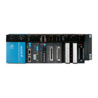
LSIS Master-K K300S User Manual (238 pages)
Programmable Logic Controller
Brand:
LSIS
| Category:
Controller
| Size: 3 MB
Table of Contents
Chapter 1 Introduction
2
Guide to the User's Manual
3
Introduction
3
Features
4
Terminology
5
Chapter 2 System Configuration
7
Table of Contents
7
Overall Configuration
8
K200S Series
8
K300S / 1000S Series
9
System Configuration
8
Product List
10
K200S
10
K300S
12
K1000S
15
System Configuration Types
18
Basic System Configuration
18
Computer Link System
19
Network System
20
Chapter 4 CPU Modules
23
CPU Modules
24
Performance Specifications
24
Operation Processing of CPU
25
Operation Method
25
The Operation During Momentary Power Failure
26
Scan Time
27
Watchdog Timer
27
Timers
28
Counter
31
Program Structure
33
Classification of Program
33
Processing Method
33
Interrupt Processing
34
Error Handling
38
Operation Mode
39
RUN Mode
39
Stop Mode
40
PAUSE Mode
41
DEBUG Mode
42
Operation Mode Change
43
Special Functions of CPU Module
45
RTC (Real Time Clock) Function
45
Forced I/O Setting
48
Program Edit in RUN Mode
49
Self-Diagnosis
50
Direct I/O Refresh
51
System Error History
51
Memory Configuration
52
Memory Map of K200S / K300S
52
The Memory Map of K1000S
53
Assign I/O Address
54
Parts Names
55
Chapter 6 Memory Module
60
Memory Module
61
Specifications
61
K300S / K1000S
61
K200S
62
Structure
61
How to Use the Memory Module
62
Write a Program into Memory Module
62
Execute the Program of Memory Module
63
Chapter 7 I\/O Modules
64
Notes on Selecting I/O Modules
65
O Modules
65
Digital Input Modules
66
Points 12/24VDC Input Module (Source / Sink Type)
66
Points 12/24VDC Input Module (Source/Sink Type)
67
Points 12/24 VDC Input Module (Source Type)
68
Points 24VDC Input Module (Source/Sink Type)
69
Points 12/24VDC Input Module (Source/Sink Type)
73
Points 110VAC Input Module
75
Points 110VAC Input Module
76
Points 220VAC Input Module
78
Points 220VAC Input Module
79
Points 220VAC Input Module
80
Interrupt Input Module
81
Digital Output Modules
82
Points Relay Output Module
82
Points Relay Output Module
83
Points Triac Output Module
85
Points Triac Output Module
86
Points Transistor Output Module (Sink Type)
88
Points Transistor Output Module (Sink Type)
89
Points Transistor Output Module (Sink Type)
90
Points Transistor Output Module (Source Type)
92
Points Transistor Output Module (Source Type)
93
Points Transistor Output Module (Source Type)
94
Digital Input / Output Hybrid Modules
95
Points 12/24VDC Input + 8 Points Relay Output
95
Points 12/24VDC Input + 8 Points Transistor Output
97
Chapter 8 Power Supply Modules
98
Power Supply Modules
99
Selection of Power Supply Module
99
K200S
99
K300S
100
K1000S
101
Specifications
102
K200S Series
102
K300S Series
103
K1000S Series
103
Parts Names and Descriptions
104
Chapter 9 Base Boards and Cables
105
Base Boards and Cables
106
Specifications
106
Main Base
106
Expansion Base
107
Expansion Cable
107
Parts Names and Descriptions
108
Main Base
108
Expansion Base
110
Chapter 10 Installation and Wiring
111
Installation
112
Installation Environment
112
Precaution During Installation
112
Heat Protection Design of Control Box
112
Calculation of the Capacity of Power Supply
113
Handling Instructions
115
Installation and Wiring
112
Mounting / Dismounting of Module
118
Mounting a Module on a Base
118
Dismounting a Module from Base Board
121
Wiring
124
Power Supply Wiring
124
Input and Output Devices Wiring
126
Grounding
126
Cable Specifications for Wiring
127
Chapter 11 Maintenance
128
Maintenance
129
Maintenance and Inspection
129
Daily Inspection
130
Periodic Inspection
131
Chapter 12 Troubleshooting
132
Basic Procedure for Troubleshooting
133
Troubleshooting
133
Troubleshooting
134
The Power LED Is Turned off
134
The STOP LED Is Flickering
135
RUN and STOP LED Are off
136
The Load of the Output Module Is Not Operating
137
Program Download Is Unable
138
Troubleshooting Questionnaire
139
Troubleshooting Examples
140
Input Circuit Troubles and Corrective Actions
140
Output Circuit Troubles and Corrective Actions
141
Error Code List
143
Chapter 13 Rs-232C Function of K200S
146
Introduction
147
RS-232C Function of K200S
147
System Configuration
148
Connection with PC ( Without Handshake Function )
148
Connection with Monitoring Unit ( with Handshake Function )
148
Pin Assignment
149
Pin-Out of K200S RS-232C Connector
149
Connection Without Handshake Function
149
Connection with Handshake Function
149
Frame Structure
150
General Structures
150
Instruction List
151
Data Address Structure
152
Start of Data
152
Device Type
152
Data Type
153
Device Number
153
Examples of Command Execution
154
Read Single Device ( RSS )
154
Read Continuous Devices (RSB)
157
Write Single Device (WSS)
160
Write Continuous Device (WSB)
163
Register Monitoring Number
166
Execute Monitoring
169
Read the Status of PLC (RST)
171
Error Code List
174
Chapter 14 Rs-422/485 Function of K200S
176
Features
177
Introduction
177
RS-422/485 Function of K200S
177
Specification
177
Wiring
178
Wiring Diagram of RS-422 Network
178
Wiring Diagram of RS-485 Network
178
Parameter Setting
180
Basic Parameter Setting
180
High Speed Link Parameter Setting
181
Communication Status Flag
182
Error Code (D4400 ~ D4415)
182
Error Count (D4416 ~ D4431)
182
Transmission Period (D4449 ~ D4454)
184
Monitoring the Communication Status
184
Section 13
185
Chapter 15 The PID Function of K200S
186
Introduction
186
The PID Function of K200S
186
Control Actions
187
Proportional Operation (P Operation)
187
Integral Operation (I Action)
189
Derivative Operation (D Action)
191
PID Action
192
Forward / Reverse Action
193
Reference Value
194
Integral Windup
195
Realization of PID Control on the PLC
198
P Control
198
I Control
198
D Control
199
Pseudo Code of PID Control
199
PID Control Instructions
200
Pidcal
200
Example of Programming
208
System Configuration
208
Initial Setting
208
Program Description
209
Example Program for PIDCAL Instruction
210
Example Program for PIDCAL and PIDTUN Instructions
211
Section 14
213
Chapter 16 Built-In High Speed Counter Ofk200S
214
Introduction
214
Performance Specifications
214
U I L T - in High Speed Counter of K200S
214
Input Specifications
215
Pin-Out of Input Terminal
215
Name of Terminal
215
External Interface Circuit
216
W Irin G
217
Wiring Instructions
217
Wiring Examples
217
H S C Instruction
218
Introduction
218
Operation Mode (D4999)
219
Example of Program
220
1-Phase Operation Mode (D4999 = H1010)
220
1-Phase Operation Mode (D4999 = H1100)
221
2-Phase Operation Mode (D4999 = H2011)
222
2-Phase Operation Mode (D4999 = 2012)
223
2-Phase Operation Mode (D4999 = H2014)
224
Appendix
225
Flag List
226
Special Relay (F/M
226
F Relay
226
M Relay
228
Special Data Register (D Area
229
Flags Related to Communication Module
229
Link Relay (L Area
233
When Cnet Module Is Mounted
233
When the Fnet Module Is Mounted
234
Dimension
235
CPU Modules
235
I/O, Special Function Modules
236
Power Modules
237
Advertisement
Advertisement
Related Products
LSIS Master-K K200S
LSIS Master-K K1000S
LSIS MASTER-K Series
LSIS MASTER-K200S
LSIS MASTER-K300S
LSIS MASTER-K1000S
LSIS MASTER-K10S
LSIS MASTER-K30S
LSIS MASTER-K10S1
LSIS MASTER-K60S
LSIS Categories
Controller
Inverter
Control Unit
DC Drives
Relays
More LSIS Manuals
Login
Sign In
OR
Sign in with Facebook
Sign in with Google
Upload manual
Upload from disk
Upload from URL