Sign In
Upload
Manuals
Brands
LSIS Manuals
DC Drives
LSLV-H100
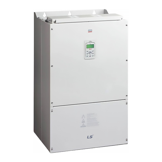
LSIS LSLV-H100 Manuals
Manuals and User Guides for LSIS LSLV-H100. We have
2
LSIS LSLV-H100 manuals available for free PDF download: User Manual, Operation Manual
LSIS LSLV-H100 User Manual (659 pages)
AC Variable Speed Drive
Brand:
LSIS
| Category:
DC Drives
| Size: 19 MB
Table of Contents
Table of Contents
6
Preparing the Installation
14
Product Identification
14
Part Names
16
Installation Considerations
23
Selecting and Preparing a Site for Installation
24
Cable Selection
27
Installing the Inverter
30
Mounting the Inverter
32
Enabling the RTC (Real-Time Clock) Battery
36
Cable Wiring
39
Post-Installation Checklist
61
Test Run
63
Perform Basic Operations
65
About the Keypad
65
Operation Keys
65
About the Display
68
Display Modes
72
Learning to Use the Keypad
76
Display Mode Selection
76
Operation Modes
77
Switching between Groups in Parameter Display Mode
79
Switching between Groups in User & Macro Mode
80
Navigating through the Codes (Functions)
81
Navigating Directly to Different Codes
83
Parameter Settings Available in Monitor Mode
85
Setting the Monitor Display Items
86
Selecting the Status Bar Display Items
88
Fault Monitoring
90
Monitoring Faults During Inverter Operation
90
Monitoring Multiple Fault Trips
91
Parameter Initialization
92
Learning Basic Features
93
Switching between the Operation Modes (HAND / AUTO / OFF)
96
Setting Frequency Reference
101
Keypad as the Source (Keypad-1 Setting)
102
Keypad as the Source (Keypad-2 Setting)
102
V1 Terminal as the Source
102
Setting a Frequency Reference with Input Voltage (Terminal I2)
112
Setting a Frequency with TI Pulse Input
113
Setting a Frequency Reference Via RS-485 Communication
115
Frequency Hold by Analog Input
116
Changing the Displayed Units (Hz↔Rpm)
117
Setting Multi-Step Frequency
117
Command Source Configuration
119
The Keypad as a Command Input Device
119
Commands)
120
Terminal Block as a Command Input Device (Run and Rotation Direction Commands)
121
Communication as a Command Input Device
122
Forward or Reverse Run Prevention
123
Power-On Run
124
Reset and Restart
126
Setting Acceleration and Deceleration Times
127
Acc/Dec Time Based on Maximum Frequency
127
Acc/Dec Time Based on Operation Frequency
130
Multi-Step Acc/Dec Time Configuration
131
Configuring Acc/Dec Time Switch Frequency
133
Acc/Dec Pattern Configuration
134
Stopping the Acc/Dec Operation
137
V/F (Voltage/Frequency) Control
138
Linear V/F Pattern Operation
138
Square Reduction V/Fpattern Operation
139
User V/F Pattern Operation
140
Torque Boost
142
Manual Torque Boost
142
Auto Torque Boost
143
Auto Torque Boost 2 (no Motor Parameter Tuning Required)
143
Output Voltage Setting
144
Start Mode Setting
145
Acceleration Start
145
Start after DC Braking
145
Stop Mode Setting
146
Deceleration Stop
146
Stop after DC Braking
147
Free Run Stop
148
Power Braking
149
Frequency Limit
150
Frequency Limit Using Maximum Frequency and Start Frequency
150
Frequency Limit Using Upper and Lower Limit Frequency Values
150
Frequency Jump
153
Nd Operation Mode Setting
154
Multi-Function Input Terminal Control
155
Multi-Function Input Terminal On/Off Delay Control
157
Learning Advanced Features
158
Operating with Auxiliary References
160
Jog Operation
166
Jog Operation 1-Forward Jog by Multi-Function Terminal
166
Jog Operation 2-Forward/Reverse Jog by Multi-Function Terminal
167
Up-Down Operation
168
3- Wire Operation
170
Safe Operation Mode
171
Dwell Operation
173
Slip Compensation Operation
175
PID Control
176
PID Basic Operation
177
Soft Fill Operation
192
PID Sleep Mode
194
PID Switching (PID Openloop)
196
External PID
197
Damper Operation
207
Lubrication Operation
209
Flow Compensation
210
Payback Counter
211
Pump Clean Operation
213
Start & End Ramp Operation
217
Decelerating Valve Ramping
219
Load Tuning
220
Level Detection
222
Pipe Break Detection
226
Pre-Heating Function
229
Auto Tuning
232
Time Event Scheduling
235
Kinetic Energy Buffering
250
Anti-Hunting Regulation (Resonance Prevention)
252
Fire Mode Operation
253
Energy Saving Operation
255
Manual Energy Saving Operation
255
Automatic Energy Saving Operation
255
Speed Search Operation
256
Auto Restart Settings
261
Operational Noise Settings (Carrier Frequency Settings)
263
Nd Motor Operation
264
Supply Power Transition
266
Cooling Fan Control
267
Input Power Frequency and Voltage Settings
268
Read, Write, and Save Parameters
269
Parameter Initialization
270
Parameter View Lock
271
Parameter Lock
271
Changed Parameter Display
272
User Group
273
Easy Start on
274
Config (CNF) Mode
276
Macro Selection
277
Timer Settings
278
Multiple Motor Control (MMC)
279
Multiple Motor Control (MMC) Basic Sequence
287
Standby Motor
292
Auto Change
293
Interlock
299
Aux Motor Time Change
303
Regular Bypass
304
Aux Motor PID Compensation
305
Master Follower
307
Multi-Function Output On/Off Control
313
Press Regeneration Prevention
314
Analog Output
316
Voltage and Current Analog Output
316
Analog Pulse Output
319
Digital Output
322
Multi-Function Output Terminal and Relay Settings
322
Fault Trip Output Using Multi-Function Output Terminal and Relay
327
Multi-Function Output Terminal Delay Time Settings
328
Operation State Monitor
329
Operation Time Monitor
331
Poweron Resume Using the Communication
332
Learning Protection Features
334
Motor Protection
334
Electronic Thermal Motor Overheating Prevention (ETH)
334
Motor over Heat Sensor
336
Overload Early Warning and Trip
338
Stall Prevention and Flux Braking
340
Inverter and Sequence Protection
344
Open-Phase Protection
344
External Trip Signal
345
Inverter Overload Protection (IOLT)
346
Speed Command Loss
347
Dynamic Braking (DB) Resistor Configuration
351
Low Battery Voltage Warning
352
Under Load Fault Trip and Warning
353
Fan Fault Detection
354
Low Voltage Fault Trip
355
Selecting Low Voltage 2 Fault During Operation
355
Output Block Via the Multi-Function Terminal
356
Trip Status Reset
356
Operation Mode for Option Card Trip
357
No Motor Trip
358
Broken Belt
359
Parts Life Expectancy
360
Main Capacitor Life Estimation
360
Fan Life Estimation
362
Fault/Warning List
364
Communication Features
367
Communication Standards
367
Communication System Configuration
368
Communication Line Connection
368
Setting Communication Parameters
370
Setting Operation Command and Frequency
372
Command Loss Protective Operation
372
LS INV 485/Modbus-RTU Communication
375
Setting Virtual Multi-Function Input
375
Saving Parameters Defined by Communication
375
Total Memory Map for Communication
377
Parameter Group for Data Transmission
378
Parameter Group for User/Macro Group
379
LS INV 485 Protocol
380
Modbus-RTU Protocol
386
Compatible Common Area Parameter
391
H100 Expansion Common Area Parameter
395
Bacnet Communication
411
What Is Bacnet Communication
411
Bacnet Communication Standards
411
Bacnet Quick Communication Start
411
Protocol Implementation
414
Object Map
414
Metasys-N2 Communication
423
Metasys-N2 Quick Communication Start
423
Metasys-N2 Communication Standard
423
Metasys-N2 Protocol I/O Point Map
424
Table of Functions
428
Drive Group (DRV)
428
Basic Function Group (BAS)
433
Expanded Function Group (ADV)
440
Control Function Group (CON)
446
Input Terminal Group (IN)
449
Output Terminal Block Function Group (OUT)
458
Communication Function Group (COM)
464
Advanced Function Group(PID Functions)
471
EPID Function Group (EPID)
483
Application 1 Function Group (AP1)
490
Application 2 Function Group (AP2)
496
Application 3 Function Group (AP3)
502
Protection Function Group (PRT)
509
2Nd Motor Function Group (M2)
519
Trip (TRIP Last-X) and Config (CNF) Mode
523
Trip Mode (TRP Last-X)
523
Config Mode (CNF)
524
Macro Groups
529
Compressor (MC1) Group
529
Supply Fan (MC2) Group
532
Exhaust Fan (MC3) Group
534
Cooling Tower (MC4) Group
555
Circululation Pump (MC5) Group
558
Vacuum Pump (MC6) Group
562
Constant Torque (MC7) Group
571
Troubleshooting
574
Trip and Warning
574
Fault Trips
574
Warning Message
578
Troubleshooting Fault Trips
579
Troubleshooting Other Faults
582
Maintenance
589
Regular Inspection Lists
589
Daily Inspection
589
Annual Inspection
590
Bi-Annual Inspection
592
Real Time Clock (RTC) Battery Replacement
593
Storage and Disposal
597
Storage
597
Disposal
597
Technical Specification
598
Input and Output Specifications
598
Product Specification Details
604
External Dimensions
608
Peripheral Devices
613
Fuse and Reactors Specifications
616
Terminal Screw Specifications
617
Dynamic Breaking Unit (DBU) and Resistors
619
Dynamic Breaking Unit (DBU)
619
Terminal Arrangement
621
Dynamic Breaking (Db)Unit & DB Resistor Basic Wiring
625
Dimensions
626
Display Functions
629
DB Resistors
629
Inverter Continuous Rated Current Derating
631
Applying Drives to Single-Phase Input Application
635
Introduction
635
Power(Hp), Input Current and Output Current
636
Input Frequency and Voltage Tolerance
637
Wiring
638
Precautions for 1-Phase Input to 3-Phase Drive
638
Product Warranty
639
UL Mark
641
EAC Mark
641
Index
646
Advertisement
LSIS LSLV-H100 Operation Manual (610 pages)
Brand:
LSIS
| Category:
Inverter
| Size: 24 MB
Table of Contents
Table of Contents
6
Preparing the Installation
15
Product Identification
15
Part Names
17
Installation Considerations
19
Selecting and Preparing a Site for Installation
20
Cable Selection
24
Installing the Inverter
28
Mounting the Inverter
30
Enabling the RTC (Real-Time Clock) Battery
33
Cable Wiring
36
Post-Installation Checklist
57
Test Run
59
Learning to Perform Basic Operations
62
About the Keypad
62
Operation Keys
62
About the Display
64
Display Modes
68
Learning to Use the Keypad
72
Display Mode Selection
72
Operation Modes
73
Switching between Groups in Parameter Display Mode
75
Switching between Groups in User & Macro Mode
76
Navigating through the Codes (Functions)
77
Navigating Directly to Different Codes
79
Parameter Settings Available in Monitor Mode
80
Setting the Monitor Display Items
82
Selecting the Status Bar Display Items
83
Fault Monitoring
85
Monitoring Faults During Inverter Operation
85
Monitoring Multiple Fault Trips
86
Parameter Initialization
87
Learning Basic Features
89
Switching between the Operation Modes (HAND / AUTO / OFF)
92
Setting Frequency Reference
97
Keypad as the Source (Keypad-1 Setting)
98
Keypad as the Source (Keypad-2 Setting)
98
V1 Terminal as the Source
98
Setting a Frequency Reference with Input Voltage (Terminal I2)
109
Setting a Frequency with TI Pulse Input
110
Setting a Frequency Reference Via RS-485 Communication
112
Frequency Hold by Analog Input
113
Changing the Displayed Units (Hz↔Rpm)
114
Setting Multi-Step Frequency
114
Command Source Configuration
116
The Keypad as a Command Input Device
116
Terminal Block as a Command Input Device (Fwd/Rev Run Commands)
117
Terminal Block as a Command Input Device (Run and Rotation Direction Commands)
118
Communication as a Command Input Device
119
Forward or Reverse Run Prevention
119
Power-On Run
121
Reset and Restart
123
Setting Acceleration and Deceleration Times
124
Acc/Dec Time Based on Maximum Frequency
124
Acc/Dec Time Based on Operation Frequency
126
Multi-Step Acc/Dec Time Configuration
127
Configuring Acc/Dec Time Switch Frequency
128
Acc/Dec Pattern Configuration
131
Stopping the Acc/Dec Operation
133
V/F (Voltage/Frequency) Control
134
Linear V/F Pattern Operation
134
Square Reduction V/Fpattern Operation
135
User V/F Pattern Operation
136
Torque Boost
138
Manual Torque Boost
138
Auto Torque Boost
139
Auto Torque Boost 2 (no Motor Parameter Tuning Required)
139
Output Voltage Setting
141
Start Mode Setting
142
Acceleration Start
142
Start after DC Braking
142
Stop Mode Setting
143
Deceleration Stop
143
Stop after DC Braking
144
Free Run Stop
145
Power Braking
146
Frequency Limit
147
Frequency Limit Using Maximum Frequency and Start Frequency
147
Frequency Limit Using Upper and Lower Limit Frequency Values
147
Frequency Jump
150
Nd Operation Mode Setting
151
Multi-Function Input Terminal Control
153
Multi-Function Input Terminal On/Off Delay Control
155
Learning Advanced Features
156
Operating with Auxiliary References
158
Jog Operation
163
Jog Operation 1-Forward Jog by Multi-Function Terminal
163
Jog Operation 2-Forward/Reverse Jog by Multi-Function Terminal
164
Up-Down Operation
165
3- Wire Operation
166
Safe Operation Mode
167
Dwell Operation
169
Slip Compensation Operation
172
PID Control
173
PID Basic Operation
174
Soft Fill Operation
188
PID Sleep Mode
190
PID Switching (PID Openloop)
192
External PID
193
Damper Operation
203
Lubrication Operation
205
Flow Compensation
206
Payback Counter
208
Pump Clean Operation
209
Start & End Ramp Operation
214
Decelerating Valve Ramping
215
Load Tuning
217
Level Detection
219
Pipe Break Detection
222
Pre-Heating Function
224
Auto Tuning
226
Time Event Scheduling
229
Kinetic Energy Buffering
243
Anti-Hunting Regulation (Resonance Prevention)
246
Fire Mode Operation
247
Energy Saving Operation
249
Manual Energy Saving Operation
249
Automatic Energy Saving Operation
249
Speed Search Operation
250
Auto Restart Settings
254
Operational Noise Settings (Carrier Frequency Settings)
256
Nd Motor Operation
257
Supply Power Transition
260
Cooling Fan Control
261
Input Power Frequency and Voltage Settings
262
Read, Write, and Save Parameters
263
Parameter Initialization
264
Parameter View Lock
265
Parameter Lock
266
Changed Parameter Display
267
User Group
268
Easy Start on
270
Config (CNF) Mode
271
Macro Selection
272
Timer Settings
273
Multiple Motor Control (MMC)
274
Multiple Motor Control (MMC) Basic Sequence
282
Standby Motor
286
Auto Change
287
Interlock
295
Aux Motor Time Change
299
Regular Bypass
301
Aux Motor PID Compensation
303
Master Follower
304
Multi-Function Output On/Off Control
311
Press Regeneration Prevention
311
Analog Output
313
Voltage and Current Analog Output
313
Analog Pulse Output
316
Digital Output
319
Multi-Function Output Terminal and Relay Settings
319
Fault Trip Output Using Multi-Function Output Terminal and Relay
324
Multi-Function Output Terminal Delay Time Settings
325
Operation State Monitor
326
Operation Time Monitor
328
Poweron Resume Using the Serial Communication
329
Learning Protection Features
331
Motor Protection
331
Electronic Thermal Motor Overheating Prevention (ETH)
331
Motor over Heat Sensor
332
Overload Early Warning and Trip
335
Stall Prevention and Flux Braking
337
Inverter and Sequence Protection
341
Open-Phase Protection
341
External Trip Signal
342
Inverter Overload Protection (IOLT)
343
Speed Command Loss
343
Dynamic Braking (DB) Resistor Configuration
347
Low Battery Voltage Warning
348
Under Load Fault Trip and Warning
349
Fan Fault Detection
350
Low Voltage Fault Trip
351
Selecting Low Voltage 2 Fault During Operation
352
Output Block Via the Multi-Function Terminal
352
Trip Status Reset
353
Operation Mode for Option Card Trip
353
No Motor Trip
354
Broken Belt
354
Parts Life Expectancy
356
Main Capacitor Life Estimation
356
Fan Life Estimation
357
Fault/Warning List
359
Communication Features
363
Communication Standards
363
Communication System Configuration
364
Communication Line Connection
364
Setting Communication Parameters
365
Setting Operation Command and Frequency
367
Command Loss Protective Operation
367
LS INV 485/Modbus-RTU Communication
370
Setting Virtual Multi-Function Input
370
Saving Parameters Defined by Communication
370
Total Memory Map for Communication
371
Parameter Group for Data Transmission
372
Parameter Group for User/Macro Group
373
LS INV 485 Protocol
374
Modbus-RTU Protocol
380
Compatible Common Area Parameter
384
H100 Expansion Common Area Parameter
388
Bacnet Communication
403
What Is Bacnet Communication
403
Bacnet Communication Standards
403
Bacnet Quick Communication Start
404
Protocol Implementation
406
Object Map
407
Metasys-N2 Communication
414
Metasys-N2 Quick Communication Start
414
Metasys-N2 Communication Standard
414
Metasys-N2 Protocol I/O Point Map
416
Table of Functions
420
Drive Group (DRV)
420
Basic Function Group (BAS)
424
Expanded Function Group (ADV)
429
Control Function Group (CON)
437
Input Terminal Group (IN)
440
Output Terminal Block Function Group (OUT)
448
Communication Function Group (COM)
454
Advanced Function Group(PID Functions)
461
EPID Function Group (EPID)
473
Application 1 Function Group (AP1)
481
Application 2 Function Group (AP2)
487
Application 3 Function Group (AP3)
493
Protection Function Group (PRT)
500
2Nd Motor Function Group (M2)
510
Trip (TRIP Last-X) and Config (CNF) Mode
512
Trip Mode (TRP Last-X)
512
Config Mode (CNF)
514
Macro Groups
519
Compressor (MC1) Group
519
Supply Fan (MC2) Group
520
Exhaust Fan (MC3) Group
522
Cooling Tower (MC4) Group
525
Circululation Pump (MC5) Group
526
Vacuum Pump (MC6) Group
528
Constant Torque (MC7) Group
530
Troubleshooting
534
Trip and Warning
534
Fault Trips
534
Warning Message
537
Troubleshooting Fault Trips
539
Troubleshooting Other Faults
541
Maintenance
548
Regular Inspection Lists
548
Daily Inspection
548
Annual Inspection
549
Bi-Annual Inspection
551
Real Time Clock (RTC) Battery Replacement
552
Storage and Disposal
555
Storage
555
Disposal
555
Technical Specification
556
Input and Output Specifications
556
Product Specification Details
561
External Dimensions (IP 20 Type)
564
Peripheral Devices
566
Fuse and Reactors Specifications
568
Terminal Screw Specifications
569
Dynamic Breaking Unit (DBU) and Resistors
571
Dynamic Breaking Unit (DBU)
571
Terminal Arrangement
574
Dynamic Breaking (Db)Unit & DB Resistor Basic Wiring
577
Dimensions
578
Display Functions
581
DB Resistors
582
Inverter Continuous Rated Current Derating
583
Applying Drives to Single-Phase Input Application
587
Introduction
587
Power(Hp), Input Current and Output Current
588
Input Frequency and Voltage Tolerance
589
Wiring
590
Precautions for 1-Phase Input to 3-Phase Drive
590
Product Warranty
591
UL Mark
593
EAC Mark
593
Index
597
Advertisement
Related Products
LSIS LSLV4000H100-4COFD
LSIS LSLV1320H100-4COFD
LSIS LSLV0900H100-4COFD
LSIS LSLV0750H100-4COFD
LSIS LSLV0550H100-4COFN
LSIS LSLV0450H100-4COFD
LSIS LSLV0220H100-4COFN
LSIS LSLV0185H100-4COFN
LSIS LSLV0022H100-4COFN
LSIS LSLV-S100 Series
LSIS Categories
Controller
Inverter
Control Unit
DC Drives
Relays
More LSIS Manuals
Login
Sign In
OR
Sign in with Facebook
Sign in with Google
Upload manual
Upload from disk
Upload from URL