Sign In
Upload
Manuals
Brands
LS Mecapion Manuals
Servo Drives
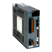
L7 A001
User Manuals: LS Mecapion L7 A001 AC Servo Drive
Manuals and User Guides for LS Mecapion L7 A001 AC Servo Drive. We have
1
LS Mecapion L7 A001 AC Servo Drive manual available for free PDF download: User Manual
LS Mecapion L7 A001 User Manual (222 pages)
AC Servo
Brand:
LS Mecapion
| Category:
Servo Drives
| Size: 7 MB
Table of Contents
Introduction
3
Safety Precautions
4
Table of Contents
9
Table of Contents
10
1 Product Components and Signals
13
Product Components
13
Product Verification
13
Part Names
15
System Configuration
19
Overview
19
Wiring Diagram of the Entire CN1 Connector
21
Example of Position Operation Mode Wiring
22
Example of Speed Operation Mode Wiring
23
Example of Torque Operation Mode Wiring
24
Examples of Speed / Position Operation Mode Wiring
25
Example of Position/Torque Operation Mode Wiring
27
Signals
28
Digital Input Contact Signal
28
Analog Input Contact Signal
29
Digital Output Contact Signal
29
Monitor Output Signal and Output Power
30
Pulse Train Input Signal
30
Encoder Output Signal
31
2 Installation
33
Servo Motor
33
Usage Environment
33
Prevention of Excessive Shock
33
Motor Connection
33
Load Device Connection
34
Cable Installation
34
Servo Drive
35
Usage Environment
35
Installation Inside the Control Panel
36
Power Wiring
37
3 Wiring Method
39
Internal Block Diagram
39
L7 Drive Block Diagram [L7SA001□ - L7SA004□]
39
L7 Drive Block Diagram [L7SA008□ - L7SA035□]
40
Power Wiring
41
L7 Drive Wiring Diagram [L7SA001□ - L7SA035□]
41
Dimensions for Power Circuit Electrical Parts
42
Timing Diagram
43
Timing Diagram During Power Input
43
Timing Diagram at the Time of Alarm Trigger
44
Control Signal Wiring
45
Contact Input Signal
45
Contact Output Signal
46
Analog Input/Output Signals
47
Pulse Train Input Signal
48
Encoder Output Signal
49
Quadrature Encoder Signaling Unit (CN2) Wiring
50
Serial Encoder Signaling Unit (CN2) Wiring
51
APCS-ECS Cable
51
Transmission of Absolute Encoder Data
53
4 Parameters
55
How to Use the Loader
55
Name and Function of each Part
55
Status Summary Display
56
Parameter Handling
58
Data Display
62
External Input Contact Signal Display [St-14]
64
External Input Signal and Logic Definition
65
External Output Contact Signal Display [St-15]
73
External Output Signal and Logic Definition
74
Parameter Description
80
Parameter System
80
Operation Status Display Parameter
81
System Setting Parameter
84
Control Setting Parameter
88
Input/Output Setting Parameter
91
Speed Operation Setting Parameter
94
Position Operation Setting Parameter
96
Operation Handling Parameter
99
Operation Status Display
103
Status Display [St-00]
103
Speed Display
103
Position Display
103
Torque and Load Display
103
I/O Status Display
104
Miscellaneous Status and Data Display
104
Version Display
105
Parameter Setting
106
System Parameter Setting
106
Control Parameter Setting
109
Analog Input/Output Parameter Setting
113
Input/Output Contact Point Parameter Setting
115
Speed Operation Parameter Setting
117
Position Operation Parameter Setting
118
Alarms and Warnings
120
Servo Alarm Status Summary Display List
120
Servo Warning Status Summary Display List
122
Motor Type and ID (to be Continued on the Next Page)
123
5 Handling and Operation
125
What to Check before Operation
125
Wiring Check
125
Drive Signal (CN1) Wiring Check
125
Surrounding Environment Check
125
Machine Status Check
125
System Parameter Check
126
Handling
127
Manual JOG Operation [Cn-00]
127
Program JOG Operation [Cn-01]
128
Alarm Reset [Cn-02]
129
Reading Alarm History [Cn-03]
130
Alarm History Reset [Cn-04]
131
Auto Gain Tuning [Cn-05]
132
Phase Z Search Operation [Cn-06]
133
Input Contact Forced ON/OFF [Cn-07]
134
Output Contact Forced ON/OFF [Cn-08]
136
Parameter Reset [Cn-09]
137
Automatic Speed Command Offset Correction [Cn-10]
138
Automatic Torque Command Offset Correction [Cn-11]
139
Manual Speed Command Offset Correction [Cn-12]
140
Manual Torque Command Offset Correction [Cn-13]
141
Instantaneous Maximum Load Factor Initialization [Cn-15]
142
Parameter Lock[Cn-16]
143
Current Offset[Cn-17]
144
6 Communication Protocol
145
Overview and Communication Specifications
145
Overview
145
Communication Specifications and Cable Access Rate
146
Communication Protocol Base Structure
147
Sending/Receiving Packet Structure
147
Protocol Command Codes
149
L7 Servo Drive Communication Address Table
154
Operation Status Parameter Communication Address Table
154
System Parameter Communication Address Table
156
Control Parameter Communication Address Table
158
Input/Output Parameter Communication Address Table
160
Speed Operation Parameter Communication Address Table
161
Position Operation Parameter Communication Address Table
162
7 Product Specifications
163
Servo Motor
163
Product Features
163
Outline Drawing
176
Servo Drive
185
Product Features
185
Outline Drawing
187
Options and Peripheral Devices
189
8 Maintenance and Inspection
197
Precautions
197
What to Inspect
197
Parts Replacement Cycle
198
Diagnosis of Abnormality and Troubleshooting
199
Servo Motor
199
Servo Drive
200
9 Appendix
211
Motor Type and ID (to be Continued on the Next Page)
212
Test Drive Procedure
214
Quality Assurance
219
User Manual Revision History
220
Advertisement
Advertisement
Related Products
LS Mecapion L7 A002
LS Mecapion L7 A010
LS Mecapion L7 A004
LS Mecapion L7 A020
LS Mecapion L7 A035
LS Mecapion L7 A08
LS Mecapion L7 Series
LS Mecapion Categories
Servo Drives
More LS Mecapion Manuals
Login
Sign In
OR
Sign in with Facebook
Sign in with Google
Upload manual
Upload from disk
Upload from URL