Table of Contents
Advertisement
Advertisement
Table of Contents

Summary of Contents for LS Mecapion L7 Series
- Page 1 VER 1.5...
-
Page 3: Introduction
LS Mecapion. The patent, trademark, copyright and other intellectual property rights in this user manual are reserved by LS Mecapion. No use for purposes other than those related to the product of LS Mecapion shall be authorized. -
Page 4: Safety Precautions
Safety Precautions Safety Precautions Safety precautions are categorized as either Danger or Caution, depending on the seriousness of the precaution. Precautions Definition Failure to comply with guidelines may cause death or serious injury. Danger Failure to comply with guidelines may cause injury or property damage. Caution ... - Page 5 Safety Precautions Installation Precautions Store and use the product in an environment as follows: Conditions Environment Servo Drive Servo Motor 0 ~ 50 ℃ 0 ~ 40 ℃ Usage temp. -20 ~ 65 ℃ -20 ~ 60 ℃ Storage temp. Usage Below 80% RH humidity...
- Page 6 Safety Precautions Wiring Precautions Caution Be sure to use AC 200-230 V for the input power of the servo drive. Be sure to connect the servo drive ground terminal. Do not connect commercial power directly to the servo motor. ...
- Page 7 Safety Precautions Precautions for Use Caution Install an emergency stop circuit on the outside to immediately stop operation if necessary. Reset the alarm when the servo is off. Be warned that the system restarts immediately if the alarm is reset while the servo is on.
- Page 8 Safety Precautions EEPROM Lifespan Caution EEPROM is rewritable up to 1 million times for the purpose of, among others, recording parameter settings. The servo drive may malfunction depending on the lifespan of EEPROM when the total counts of the following tasks exceed 1 million. ...
-
Page 9: Table Of Contents
Table of Contents Table of Contents Introduction ........................iii Safety Precautions ......................iv Table of Contents ......................ix Product Components and Signals ..............1-1 Product Components ..................... 1-1 1.1.1 Product Verification ..................1-1 1.1.2 Part Names ....................1-3 System Configuration ....................1-7 1.2.1 Overview ...................... -
Page 10: Table Of Contents
Table of Contents 3.3.2 Timing Diagram at the Time of Alarm Trigger ..........3-6 Control Signal Wiring ..................... 3-7 3.4.1 Contact Input Signal ..................3-7 3.4.2 Contact Output Signal ..................3-8 3.4.3 Analog Input/Output Signals ................3-9 3.4.4 Pulse Train Input Signal................3-10 3.4.5 Encoder Output Signal ..................3-11 Quadrature Encoder Signaling Unit (CN2) Wiring ............ - Page 11 Table of Contents Alarms and Warnings ....................4-66 4.5.1 Servo Alarm Status Summary Display List ............ 4-66 4.5.2 Servo Warning Status Summary Display List ..........4-68 Motor Type and ID (to be continued on the next page) ..........4-69 Handling and Operation ..................5-1 What to Check Before Operation ...................
- Page 12 Table of Contents 7.2.1 Product Features ..................7-23 7.2.2 Outline Drawing .................... 7-25 Options and Peripheral Devices .................. 7-27 Maintenance and Inspection ................8-1 Maintenance and Inspection ..................8-1 8.1.1 Precautions ....................8-1 8.1.2 What to Inspect ....................8-1 8.1.3 Parts Replacement Cycle ................
-
Page 13: Product Components And Signals
1. Product Components and Signals Product Components and Signals Product Components 1.1.1 Product Verification 1. Check the name tag to verify that the product matches the model you ordered. Does the format of the servo drive's name tag match? ... - Page 14 1. Product Components and Signals Servo Motor Product Format APM – S B 04 A E K 1 G1 03 Encoder Type Motor Capacity Gearbox Servo Motor Classification Quadrature(pulse type) R3 : 30[W] 03: 1/3 A: Inc. 1024 [P/R] R5 : 50[W] 10: 1/10 B: Inc.
-
Page 15: Part Names
1. Product Components and Signals 1.1.2 Part Names Servo Motor 80 Flange or below Motor Power Cable Motor Encoder Connector Connector Encoder Cable Shaft Encoder Cover Flange Frame Housing Bearing Cap 80 Flange or below(Flat Type) Encoder connector Power connector Shaft Flange... - Page 16 1. Product Components and Signals Servo Drive L7SA 001□, L7SA 002□, L7SA 004□ Display Operation keys (Mode, Up, Down, Set) CN5: USB connector Main power connector (L1, L2, L3) CN4: RS-422 communication DC reactor connector connector (PO, PI) Short circuit when not used CN3: RS-422 communication...
- Page 17 1. Product Components and Signals L7SA 008□, L7SA 010□ Display Operation keys (Mode, Up, Down, Set) CN5: USB connector Main power connector (L1, L2, L3) CN4: RS-422 communication DC reactor connector connector (PO, PI) Short circuit when not used CN3: RS-422 communication connector...
- Page 18 1. Product Components and Signals L7SA 020□, L7SA 035□ Display Operation keys (Mode, Up, Down, Set) CN5: Main power connector USB connector (L1, L2, L3) CN4: DC reactor connector RS-422 communication (PO, PI) connector Short circuit when not used CN3: RS-422 communication connector...
-
Page 19: System Configuration
1. Product Components and Signals System Configuration 1.2.1 Overview The L7 servo system can be configured in various ways depending on its interface with the upper level controller. (1) Position Operation System The servo is run by pulse commands. You can change the location of the servo motor by changing command pulses based on a certain transfer unit. - Page 20 1. Product Components and Signals (3) Torque Operation System The servo is run by torque commands. Analog voltage-based commands are used. Upper Level Controller Servo Drive Servo Motor Torque Command Change Position Torque Torque Current Motor Torque Controller Controller Controller Controller Command Encoder...
-
Page 21: Wiring Diagram Of The Entire Cn1 Connector
1. Product Components and Signals 1.2.2 Wiring Diagram of the Entire CN1 Connector Digital Input Digital Output Note 1) (DO1) DC 24V ALARM+ +24V IN 3.3kΩ ALARM- Note 1) (DO2) (DIA) STOP READY+ (DI9) READY- (DI8) CWLIM (DO3) ZSPD (DI7) CCWLIM (DO4) BRAKE... -
Page 22: Example Of Position Operation Mode Wiring
1. Product Components and Signals 1.2.3 Example of Position Operation Mode Wiring Digital Input Digital Output Note 1) (DO1) DC 24V ALARM+ +24V IN 3.3kΩ ALARM- Note 1) (DO2) (DIA) STOP READY+ (DI9) READY- (DI8) CWLIM (DO3) ZSPD (DI7) CCWLIM (DO4) BRAKE (DI6) -
Page 23: Example Of Speed Operation Mode Wiring
1. Product Components and Signals 1.2.4 Example of Speed Operation Mode Wiring Digital Input Digital Output Note 1) (DO1) DC 24V ALARM+ +24V IN 3.3kΩ ALARM- Note 1) (DO2) (DIA) STOP READY+ (DI9) READY- (DI8) CWLIM (DO3) ZSPD (DI7) CCWLIM (DO4) BRAKE (DI6) -
Page 24: Example Of Torque Operation Mode Wiring
1. Product Components and Signals 1.2.5 Example of Torque Operation Mode Wiring Digital Input Digital Output Note 1) (DO1) DC 24V ALARM+ +24V IN 3.3kΩ ALARM- Note 1) (DO2) (DIA) STOP READY+ (DI9) READY- (DI8) CWLIM (DO3) ZSPD (DI7) CCWLIM (DO4) BRAKE (DI6) -
Page 25: Examples Of Speed / Position Operation Mode Wiring
1. Product Components and Signals 1.2.6 Examples of Speed / Position Operation Mode Wiring Digital Input Digital Output Note 1) (DO1) DC 24V ALARM+ +24V IN 3.3kΩ ALARM- Note 1) (DO2) (DIA) STOP READY+ (DI9) READY- (DI8) CWLIM (DO3) ZSPD (DI7) CCWLIM (DO4) - Page 26 1. Product Components and Signals 1.2.7 Example of Speed/Torque Mode Wiring Operation Digital Input Digital Output Note 1) (DO1) DC 24V ALARM+ +24V IN 3.3kΩ ALARM- Note 1) (DO2) (DIA) STOP READY+ (DI9) READY- (DI8) CWLIM (DO3) TLMT (DI7) CCWLIM (DO4) VLMT Note 3)
-
Page 27: Example Of Position/Torque Operation Mode Wiring
1. Product Components and Signals 1.2.8 Example of Position/Torque Operation Mode Wiring Digital Input Digital Output Note 1) (DO1) DC 24V ALARM+ +24V IN 3.3kΩ ALARM- Note 1) (DO2) (DIA) STOP READY+ (DI9) READY- (DI8) CWLIM (DO3) VLMT (DI7) CCWLIM (DO4) TLMT Note 3) -
Page 28: Signals
1. Product Components and Signals Signals 1.3.1 Digital Input Contact Signal Applicable Modes Number Name Details Speed Speed Position Position Speed Torque Factory /Position /Torque /Torque Setting Input contact +24 [V] +24 V IN power SVON Servo ON SPD1 Multi-speed 1 SPD2 Multi-speed 2 SPD3... -
Page 29: Analog Input Contact Signal
1. Product Components and Signals 1.3.2 Analog Input Contact Signal Applicable Modes Name Description Speed Speed Position Number Position Speed Torque /Position /Torque /Torque Analog speed command (-10-+10 [V]) SPDCOM Analog Speed Limit (-10-+10 [V]) Analog Torque Command (-10-+10 [V]) TRQCOM Analog torque limit (-10-+10 [V]) -
Page 30: Monitor Output Signal And Output Power
1. Product Components and Signals 1.3.4 Monitor Output Signal and Output Power Applicable Modes Name Description Speed Speed Position Number Position Speed Torque /Position /Torque /Torque Analog monitor MONIT1 output 1 (-10-+10 [V]) Analog monitor MONIT2 output 2 (-10-+10 [V]) Grounding for analog signals Terminal for +12 [V]... -
Page 31: Encoder Output Signal
1. Product Components and Signals 1.3.6 Encoder Output Signal Applicable Modes Name Description Speed Speed Position Number Position Speed Torque /Position /Torque /Torque Outputs encoder signals received from the motor as signals pre-scaled according to the ratio defined by [P0-14]/[P0-15]. (5 [V] line driver method) Outputs encoder Z signals received from the motor. - Page 32 1. Product Components and Signals 1-20...
-
Page 33: Installation
2. Installation Installation Servo Motor 2.1.1 Usage Environment Item Requirements Notes If the temperature at which the product will be used is Ambient 0 ∼ 40[℃] outside this range, the product must be custom-ordered temperature with consultation of the technical support team. Ambient 80[%] RH or lower Use the product in steam-free places. -
Page 34: Load Device Connection
2. Installation 2.1.4 Load Device Connection For coupling connection: Make sure that the motor shaft and the load shaft are aligned within the tolerance. 0.03 [㎜] or below (peak to peak) Load shaft Motor shaft 0.03 [㎜] or below (peak to peak) ... -
Page 35: Servo Drive
2. Installation Servo Drive 2.2.1 Usage Environment Item Requirements Notes Caution Ambient 0∼50[℃] Install a cooling fan on the control panel in to keep the temperature surrounding temperature within the required range. Caution Condensation or freezing of moisture inside the drive during Ambient 90[%] RH or prolonged periods of inactivity may damage it. -
Page 36: Installation Inside The Control Panel
2. Installation 2.2.2 Installation Inside the Control Panel Comply with the spaces specified in the following images for installation inside the control panel. 100 mm 40 mm or or longer longer 10 mm or 10 mm or 30 mm or 30 mm or longer longer... -
Page 37: Power Wiring
2. Installation 2.2.3 Power Wiring Make sure that the input power voltage is within the allowed range. Caution Overvoltage can damage the drive. Connection of commercial power to the U, V and W terminals of the drive may cause damage. Be sure to supply power via terminals L1, L2 and L3. - Page 38 2. Installation...
-
Page 39: Wiring Method
3. Wiring Method Wiring Method Internal Block Diagram 3.1.1 L7 Drive Block Diagram [L7SA001□ - L7SA004□] NOTE 1) If you use a DC reactor, connect to the PO and PI pins. NOTE 2) If you use external regenerative resistance, connect to the B+ and B pins after removing the B and BI short-circuit pins. -
Page 40: L7 Drive Block Diagram [L7Sa008□ - L7Sa035□]
3. Wiring Method 3.1.2 L7 Drive Block Diagram [L7SA008□ - L7SA035□] NOTE 1) If you use a DC reactor, connect to the PO and PI pins. NOTE 2) If you use external regenerative resistance, connect to the B+ and B pins after you remove the B and BI short-circuit pins. -
Page 41: Power Wiring
3. Wiring Method Power Wiring 3.2.1 L7 Drive Wiring Diagram [L7SA001□ - L7SA035□] (200~230V) 서보드라이브 Servo Drive R S T 주1) Note 1) DC 리액터 Main DC Reactor Main PO PI 인코더 Encoder Alarm+ +24V Alarm- 외부 주2) Note 2) External Regenerative Resistancer 회생저항... -
Page 42: Dimensions For Power Circuit Electrical Parts
3. Wiring Method 3.2.2 Dimensions for Power Circuit Electrical Parts Name L7SA001□ L7SA002□ L7SA004□ L7SA008□ L7SA010□ L7SA020□ L7SA035□ MCCB ABS33bM (8 A) 12 A 24 A Noise Filter RFY-4010M 4020M 4030M (NF) DC reactor HFN-6 (6 A) HFN-10 (10 A) HFN-30 (30 A) GMC-9 (11 A) GMC-18 (18 A) -
Page 43: Timing Diagram
Timing Diagram 3.3.1 Timing Diagram During Power Input For L7 Series, connect single-phase power to the C1 and C2 terminals to supply power to the control circuit, and three-phase power to L1, L2, and L3 to supply power to the main circuit. -
Page 44: Timing Diagram At The Time Of Alarm Trigger
3. Wiring Method 3.3.2 Timing Diagram at the Time of Alarm Trigger When the alarm triggers in the servo drive, PWM is blocked and the motor stops. Caution Never reset the alarm before you solve the problem that triggered the alarm and change the command signal (Servo ON) to OFF. -
Page 45: Control Signal Wiring
3. Wiring Method Control Signal Wiring 3.4.1 Contact Input Signal Caution 1. There are two input contacts based on the characteristics of individual signals: contact A and contact B. They can be set by [P2-08] and [P2-09]. 2. It is possible to turn each contact on or off forcibly with [Cn-07]. Take extra caution, however, because each contact is automatically turned off when power is off. -
Page 46: Contact Output Signal
3. Wiring Method 3.4.2 Contact Output Signal Caution 1. There are two output contacts based on the characteristics of individual signals: contact A and contact B. They can be set by [P2-10]. 4. It is possible to turn each contact on or off forcibly with [Cn-08]. Take extra caution, however, because each contact is automatically turned off when power is off. -
Page 47: Analog Input/Output Signals
3. Wiring Method 3.4.3 Analog Input/Output Signals 1. Keep GND as 0 [V] of control power. 2. Keep the input signal command voltage within ±10 [V], and input impedance at 22 [㏀]. 3. Output signal voltage for Monitor 1 (No. 28) and Monitor 2 (No. 29) is ±10 [V]. Servo Drive Twisted Pair Shield Wire... -
Page 48: Pulse Train Input Signal
3. Wiring Method 3.4.4 Pulse Train Input Signal (1) Line Driver (5 [V]) Pulse Input Servo Drive Upper level controller Twisted Pair Shield Wire Line driver Line receiver (2) Open Collector (24 [V]) Pulse Input Servo Drive Upper level controller GND24 +24 [V] Pulse COM... -
Page 49: Encoder Output Signal
3. Wiring Method (4) PNP Open Collector Pulse Command Upper level controller Servo Drive note 2) Power When using 24 [V] power: Resistance R = 1.5 [kΩ], 1/2 [W] NOTE 1) When using 12 [V] power: Resistance R = 560-680 [Ω], 1/2 [W] When using 5 [V] power: Resistance R = 100-150 [Ω], 1/2 [W] 3.4.5 Encoder Output Signal Connect the GND terminal of the upper level controller and the GND terminal of CN1... -
Page 50: Quadrature Encoder Signaling Unit (Cn2) Wiring
3. Wiring Method Quadrature Encoder Signaling Unit (CN2) Wiring 3.5.1 APCS-E AS Cable AWG24 7Pair Twisted Servo Motor Servo Drive Shield Wire Encoder Cable Connector(CN2) Cable Maker – 3M Connector 10314-52A0-008 Maker - AMP 10114-3000VE 172163-1 Frame 170361-1 3.5.2 APCS-E BS Cable AWG24 7Pair Twisted Servo Motor... -
Page 51: Serial Encoder Signaling Unit (Cn2) Wiring
3. Wiring Method Serial Encoder Signaling Unit (CN2) Wiring 3.6.1 APCS-E CS Cable AWG24 4Pair Twisted Servo Motor Servo Drive Shield Wire Encoder Cable Connector(CN2) Cable Maker – 3M Connector 10314-52A0-008 Maker - AMP 10114-3000VE 172161-1 Frame 170361-1 3.6.2 APCS-E DS Cable 3-13... - Page 52 3. Wiring Method 3.6.3 APCS-E ES Cable Servo Motor Servo Drive 인코더 Encoder Cable Connector(CN2) Maker - 3M 10314-52A0-008 10114-3000VE Frame Connector Tyco Connector (7Ciruits) 3-14...
-
Page 53: Transmission Of Absolute Encoder Data
3. Wiring Method Transmission of Absolute Encoder Data 3.7.1 Transmission of Absolute Encoder Data Upon the absolute encoder's request for absolute data, the data of the absolute encoder are transmitted to the upper level controller in the form of quadrature pulses through the output of the encoder output signals, AO and BO. -
Page 55: Parameters
4. Parameters Parameters How to Use the Loader 4.1.1 Name and Function of Each Part Display 5-digit FND data. Digit 5 Digit 4 Digit 3 Digit 2 Digit 1 Displays the decimal point. E.g.) 123.4 [MODE]: Change display mode. [/LEFT]: Move to another data digit. In the case of 16 bits, the minus symbol is used. -
Page 56: Status Summary Display
4. Parameters 4.1.2 Status Summary Display (1) Status Summary Display in Speed Mode ① Example of the OFF status of the servo in speed control mode DIGIT 3-1: Displays the current status of the servo. bb - Servo OFF ... - Page 57 4. Parameters (2) Servo Operation Status Summary Display List The following list explains the operation status summary display of different modes of the servo. Operation Status Function Notes Screen Displays the servo's OFF status when in the position mode. Displays the servo's ON status when in position mode.
-
Page 58: Parameter Handling
4. Parameters 4.1.3 Parameter Handling (1) Parameter Movement Example of changing speed control mode to position control mode ([P0-03]: 00001 -> 00002) St-26 P0-27 P4-13 Cn-15 P1-25 P2-22 P3-20 St-25 P0-26 P4-12 Cn-14 St-24 P0-25 P4-11 Cn-13 DOWN St-02 P0-02 P4-02 Cn-02 St-01... - Page 59 4. Parameters (2) Example of changing speed control mode to position control mode ( [P0-03]: 00001 -> 00002 ) Orde Loader Displays Keys to Use What to Do Displays the speed control mode with main power and control power permitted. Press [MODE] to move to [P0-00].
- Page 60 4. Parameters (3) Example of changing speed proportional gain 2 ([P1-07]: 200 [rad/s] -> 500 [rad/s]) Orde Loader Displays Keys to Use What to Do Displays the speed control mode with main power and control power permitted. Press [MODE] to move to [P1-00]. Press [UP] or [DOWN] to move to [P1- 07].
- Page 61 4. Parameters (4) Example of changing DAC output offset 1 ([P0-20]: 0 [Unit/V] -> -500 [Unit/V]) Orde Loader Displays Keys to Use What to Do Displays the speed control mode with main power and control power permitted. Press [MODE] to move to [P1-00]. Press [UP] or [DOWN] to move to [P0- 20].
-
Page 62: Data Display
4. Parameters 4.1.4 Data Display (1) Binary ① Minimum (0b00000) ② Maximum (0b11111) (2) Hex ① Minimum (0x0000) ② Maximum (0xFFFF) (3) 16-bit Unsigned Integer ① E.g.) 0 ② E.g.) +1234 (4) 16-bit Signed Integer ① E.g.) -1234 ② E.g.) +5678 ①... - Page 63 4. Parameters (6) 32-bit Signed Integer Data Display ① Minimum (-2147483648) Display upper two digits Display middle four digits Display lower four digits ② Maximum (2147483647) Display upper two digits Display middle four digits Display lower four digits E.g.) [St-16]: Displayed as Upper = 0, Middle = 0012, and Lower = 2071 Order Loader Displays...
-
Page 64: External Input Contact Signal Display [St-14]
4. Parameters 4.1.5 External Input Contact Signal Display [St-14] You can check whether the ON/OFF status of digital input/output signals that access the servo drive are on or off. (1) External Input Signal Display The positions of the seven segment LEDs and CN1 connector pins correspond as follows. If an LED that corresponds to a pin is turned on/off, it indicates ON/OFF accordingly. -
Page 65: External Input Signal And Logic Definition
4. Parameters 4.1.6 External Input Signal and Logic Definition The following describes how to allocate input signals and how to view them. (1) Input Signal Allocation L7 Drive allows for the allocation of a total of 19 input contact fuctions to 10 hardware contacts. - Page 66 4. Parameters Signal Name Alwa CN1 Pin Default Allocation Number Input Input Default Alloc Signal Parameter Signal Alloc setting ation Definition Allocation ated Servo ON SVON [P2-00].Set Digit 1 Multi-speed 1 SPD1 [P2-00]. Set Digit 2 [P2-00] 0x4321 Multi-speed 2 SPD2 [P2-00].
- Page 67 4. Parameters (2) Example of Changing Input Signal Allocation The input signal definition can be changed in [P2-00], [P2-01], [P2-02], [P2-03], and [P2-04]. The input signal logic definition can be changed in [P2-08] and [P2-09]. Allocate input signals as shown in the following table: Input Signal Input Allocation Number 4-13...
- Page 68 4. Parameters Signal Name Alwa CN1 Pin Default Allocation Number Input Value Input Alloc Signal After Parameter Signal Alloc ation Definition Changing Allocation ated Servo ON SVON [P2-00].Set Digit 1 Multi-speed 1 SPD1 [P2-00]. Set Digit 2 [P2-00] 0x0321 Multi-speed 2 SPD2 [P2-00].
- Page 69 4. Parameters Examples of Changing Input Signal Allocation The following is an example of changing input signal allocation. The allocation signals of SVON (CN1-47) and STOP (CN1-48) can be switched in the following sequence. Before Changing After Changing [P2-00]: [P2-02]: Order Loader Displays...
- Page 70 4. Parameters (3) Input signal logic definition L7 Drive allows for defining the logic of input signals for 10 hardware contacts from DI1 to DIA through parameters [P2-08] and [P2-09]. The logic of input signals as set in the factory is as follows. Input signal logic definition Input signal logic definition number Signal Name...
- Page 71 4. Parameters (4) Example of Changing Input Signal Logic Definitions Input signal logic definitions can be changed in [P2-08] and [P2-09]. When input signals are allocated as below, settings will be done as shown in table below. Input signal logic definition Input signal logic definition number Signal Name CN1 Pin Default Allocation Number...
- Page 72 4. Parameters Examples of changing input signal logic definitions The table below shows examples of changing input signal logic definitions. The sequence of changing logic signal contact A of SVON (CN1-47) to contact B and logic signal contact B of CCWLIM (1-20) to contact A is as follows. Before changing After changing [P2-08]:...
-
Page 73: External Output Contact Signal Display [St-15]
4. Parameters 4.1.7 External Output Contact Signal Display [St-15] You can check whether the ON/OFF status of digital input/output signals that access the servo drive are on or off. (1) External Output Signal Display The positions of the seven segment LEDs and CN1 connector pins correspond as follows. If an LED that corresponds to a pin is turned on/off, it indicates ON/OFF accordingly. -
Page 74: External Output Signal And Logic Definition
4. Parameters 4.1.8 External Output Signal and Logic Definition The following explains output signal allocation and the method of checking allocation status. (1) Output Signal Allocation Output signal definition: [P2-05], [P2-06], [P2-07] Output signal logic definition: [P2-10] The default output signal allocation is as follows: Output Signal Output Allocation Number... - Page 75 4. Parameters (2) Examples of Changing Output Signal Allocation The output signal definition can be changed in [P2-05], [P2-06], and [P2-07]. The output signal logic definition can be changed in [P2-10]. Allocate output signals as in the following table: Output Signal Output Allocation Number Signal Name...
- Page 76 4. Parameters Example of Changing Output Signal Allocation The following is an example of output signal allocation change. The sequence of switching the allocation signals of ALARM (CN1-38/39) and ZSPD (CN1- 43) is as follows: Before Changing After Changing [P2-05]: Loader Window Display Order...
- Page 77 4. Parameters (3) Output Signal Logic Definition Output signal logic definition: [P2-10] The logic of output signals as shipped from the factory is as follows. Output signal logic definitions Output signal logic definition number DO1(Contact A/Contact B) DO2(Contact A/Contact B) DO3(Contact A/Contact B) DO4(Contact A/Contact B) DO5(Contact A/Contact B)
- Page 78 4. Parameters (4) Examples of Changing Output Singal Logic Definition Output signal logic definitions can be changed at [P2-10] Set output singals as shown in the table below when they are allocated as below. Output signal logic definitions Output signal logic definition number DO1(Contact A/Contact B) DO2(Contact A/Contact B)
- Page 79 4. Parameters Example of Changing Output Signal Allocation The following is an example of output signal allocation change. The sequence of switching the allocation signals of ALM (CN1-38/39) and ZSPD (CN1-43) is as follows: Before Changing After Changing [P2-05]: Loader Window Display Order Keys to Use...
-
Page 80: Parameter Description
4. Parameters Parameter Description 4.2.1 Parameter System There are a total of eight groups of parameters. Each group is explained in the following table: Move to Parameter Parameter Initial Screen Details Another Number Group Name Parameter E.g.) In speed mode Status Summary Displays the status Display... -
Page 81: Operation Status Display Parameter
4. Parameters 4.2.2 Operation Status Display Parameter For detailed information, refer to "4.3 Operation Status Display." “**” Modification is not possible with the servo on & Power reset parameter. “*” Parameter that cannot be modified with the servo on Parameter Unit Initial Details... - Page 82 4. Parameters Parameter Unit Initial Details Code Name Minimum Maximum Accumulated overload Displays the currently accumulated load factor against rate the maximum accumulated load factor as a St-09 percentage. Accumulated overload -300.0 300.0 (Details: Refer to “4.3.4 Torque and Load Display.”) Instantaneous maximum Displays the instantaneous maximum load factor load factor...
- Page 83 4. Parameters Parameter Unit Initial Details Code Name Minimum Maximum Displays the internal temperature sensor value. Internal temperature [℃] St-19 Room temperature Rated motor speed [RPM] Displays the rated speed of the currently St-20 installed motor. Rated RPM 10000 Maximum motor speed [RPM] Displays the maximum speed of the currently St-21...
-
Page 84: System Setting Parameter
4. Parameters 4.2.3 System Setting Parameter For detailed information, refer to "4.4.1 System Parameter Setting." “**” Modification is not possible with the servo on & Power reset parameter. “*” Parameter that cannot be modified with the servo on Parameter Unit Initial Details Code... - Page 85 4. Parameters Parameter Unit Initial Details Code Name Minimum Maximum Main power input mode 0b00 Sets main power input. DIGIT 1-> 0: Single-phase power 1: 3-phase power input P0-06 Caution: Using single-phase power Power fail mode 0b00 0b11 may lower motor output. DIGIT2 ->...
- Page 86 4. Parameters Parameter Unit Initial Details Code Name Minimum Maximum DB control mode Sets DB control mode. 0: Hold after DB stop 1: Release after DB stop *P0-17 2: Release after free run stop DB control mode ...
- Page 87 4. Parameters Parameter Unit Initial Details Code Name Minimum Maximum DAC output scale 1 Sets magnification for 1-4 analog output [Unit/V] channels. (MONIT1) P0-24 Sets magnification as setting Unit/V. DAC scale1 (F) 10000 E.g.) Channel 1 scale 100 [RPM]: Output 100 (MONIT1) [RPM] as 1 [V].
-
Page 88: Control Setting Parameter
4. Parameters 4.2.4 Control Setting Parameter For detailed information, refer to "4.4.2 Control Parameter Setting." “**” Modification is not possible with the servo on & Power reset parameter. “*” Parameter that cannot be modified with the servo on Parameter Unit Initial Details Code... - Page 89 4. Parameters Parameter Unit Initial Details Code Name Minimum Maximum Speed feedback filter time Sets filter time constant for speed search values. 0.1[ms] constant (Details: Refer to “4.4.2 Control Parameter Setting.”) P1-11 Spd. feedback filter time 1000 constant Torque command filter time Sets filter time constant for torque command values.
- Page 90 4. Parameters Parameter Unit Initial Details Code Name Minimum Maximum Resonance avoidance [Hz] Sets resonance avoidance frequency. frequency P1-18 (Details: Refer to “4.4.2 Control Parameter Setting.”) Notch frequency 1000 Resonance avoidance [Hz] Sets the scope of resonance avoidance frequency. range P1-19 (Details: Refer to “4.4.2 Control Parameter Setting.”) Notch bandwidth...
-
Page 91: Input/Output Setting Parameter
4. Parameters 4.2.5 Input/Output Setting Parameter For detailed information, refer to "4.4.3 Analog Input/Output Parameter Setting" and "4.4.4 Input/Output Contact Parameter Setting." “**” Modification is not possible with the servo on & Power reset parameter. “*” Parameter that cannot be modified with the servo on Parameter Unit Initial... - Page 92 4. Parameters Parameter Unit Initial Details Code Name Minimum Maximum Input signal logic Define CN1 connector logic for a digital input 0b10001 definition 2 signal.(0: Contact B, 1: Contact A) Initial input logic definitions [P2-09]DIGIT 1 = DI6 (CN1 #46) (Contact A) ...
- Page 93 4. Parameters Parameter Unit Initial Details Code Name Minimum Maximum Analog speed offset [mV] Sets offset for analog speed commands. (Details: Refer to “4.4.3 Analog Input/Output P2-18 Analog speed Parameter Setting.”) -1000 1000 command offset Zero speed clamp speed [RPM] Sets speed range for the clamp operation of the analog zero speed command.
-
Page 94: Speed Operation Setting Parameter
4. Parameters 4.2.6 Speed Operation Setting Parameter For detailed information, refer to "4.4.5 Speed Operation Parameter Setting." “**” Modification is not possible with the servo on & Power reset parameter. “*” Parameter that cannot be modified with the servo on Parameter Unit Initial... - Page 95 4. Parameters Parameter Unit Initial Details Code Name Minimum Maximum Program JOG operation Sets operation speed/operation time for programs 1 [RPM] speed 1 to 4 during program JOG operation [Cn-01]. P3-13 A test run repeats from step 1 to step 4. Program jog speed 1 -6000 6000...
-
Page 96: Position Operation Setting Parameter
4. Parameters 4.2.7 Position Operation Setting Parameter For detailed information, refer to "4.4.6 Position Operation Parameter Setting." “**” Modification is not possible with the servo on & Power reset parameter. “*” Parameter that cannot be modified with the servo on Parameter Unit Initial... - Page 97 4. Parameters Parameter Unit Initial Details Code Name Minimum Maximum Electronic gear ratio Sets electronic gear ratio numerator/denominator 0, 1000 numerator 1 1, 2, and 3. *P4-01 Electronic Gear Electric gear num.1 30000 Ratio EGEAR EGEAR Electronic Electronic gear ratio Gear Ratio Numerator / 1000...
- Page 98 4. Parameters Parameter Unit Initial Details Code Name Minimum Maximum Backlash Sets backlash compensation in position compensation operation. Sets backlash compensation by converting the amount of backlashes to number of pulses if the position changes because of backlashes P4-13 caused by position operation. Backlash 10000 Sets in the opposite direction according to the...
-
Page 99: Operation Handling Parameter
4. Parameters 4.2.8 Operation Handling Parameter “**” Modification is not possible with the servo on & Power reset parameter. “*” Parameter that cannot be modified with the servo on Parameter Unit Initial Details Code Name Minimum Maximum Manual JOG operation The drive performs manual JOG operation by itself. - Page 100 4. Parameters Parameter Unit Initial Details Code Name Minimum Maximum Get alarm history Check the saved alarm code history. [UP] or [DOWN]: Reads alarm codes. E.g.) Recent first history [AL-42]: RST_PFAIL occurs. Cn-03 Get alarm history 01: Latest alarm ...
- Page 101 4. Parameters Parameter Unit Initial Details Code Name Minimum Maximum Auto speed command Calibrates the offset of analog speed offset correction commands automatically. The possible voltage range is from -1 V to 1 If offset voltage exceeds this range, [oVrnG] Cn-10 is displayed and there is no calibration.
- Page 102 4. Parameters Parameter Unit Initial Details Code Name Minimum Maximum Absolute encoder reset Resets the absolute encoder. Cn-14 (Details: Refer to "5.2 Handling.") Abs encoder reset Reset the instantaneous maximum load factor to Max load clear [UP]: Displays the + forward maximum load factor.
-
Page 103: Operation Status Display
4. Parameters Operation Status Display 4.3.1 Status Display [St-00] Refer to "4.1.2 Status Summary Display." 4.3.2 Speed Display 1. Current operation speed [St-01] Displays the current operation speed in [RPM]. 2. Current command speed [St-02] Displays the current command speed in [RPM]. 4.3.3 Position Display 1. -
Page 104: I/O Status Display
4. Parameters 5. Torque limit [St –11] Displays the maximum torque that the servo motor can output as a percentage of the rated torque. 6. DC link voltage [St–12] The DC link voltage of the standard drive that uses 220 [V] is approximately 300 [V]. ... -
Page 105: Version Display
4. Parameters 4.3.7 Version Display 1. Software version display [St-25] Displays the version of the currently installed software. A 0.01. 3 Encoder Version Drive capacity Drive capacity default Type 100W 200W A:Quadrature 400W B:Serial 750W 3.5kW 4-51... -
Page 106: Parameter Setting
4. Parameters Parameter Setting 4.4.1 System Parameter Setting 1. Motor ID setting [P0-00] Serial encoder: Reads the motor ID from the encoder and displays it. Incremental encoder: Sets motor ID directly. 2. Encoder setting Encoder type [P0-01] Numb Encoder Type Encoder Type... - Page 107 4. Parameters System ID [P0-05] A unique ID can be given to the servo and used for individual communication with it. 5. Main power input mode setting [P0-06] Sets the main power input mode and processing mode in case of phase loss. ...
- Page 108 4. Parameters => Encoder pulse output: 3,000 [ppr] × 1/2 = 1,500 [ppr] 14. PWM OFF delay time setting [P0-16] Sets the time span between servo OFF command and actual PWM OFF. This is to prevent the motor from slipping down the vertical axis until the motor brake comes into effect after receiving the servo off command and then the brake signal.
-
Page 109: Control Parameter Setting
4. Parameters Example: Channel 1 scale 100 =>100 [RPM] is output as 1 [V]. DAC output offset [P0-20], [P0-21], [P0-22], [P0-23] Sets offset [Unit/V] for 1-4 analog output channels. (Speed [RPM], torque [%], position command frequency [0.1 Kpps], position [pulse], DC_Link [V]) 4.4.2 Control Parameter Setting The order of setting control parameters is as follows:... - Page 110 4. Parameters (2) Position Control Gain Differ FF filter time Feedforward gain entiati constant [P1-04] [P1-05] Speed Position error Command Position Proportional command gain [P1-01] Current position Prescale Pulse output [P0-14]/[P0-15] Position command: Count the position command pulse input from outside, and then apply an electric gear ratio, and then through [P1-03] position command filter, use it as an internal position command.
- Page 111 4. Parameters speed calculation at a very low speed. Therefore, an accurate motor constant and inertia ratio are closely associated with the stability of motor speed control. Speed integral time constant [P1-08]: Calculate the integral value of the speed error, which is the difference between the command and the current speed, and convert it into a torque command by multiplying it by integral time constant.
- Page 112 4. Parameters You can set maximum torque limits for forward rotation [P1-13] and for reverse rotation [P1- 14] separately. The setting is displayed as a percentage of the rated torque and the standard is 300 [%]. (6) Gain 1<->Gain 2 Transfer Mode Setting [P1-15] 0x0F (DIGIT 1) Set speed gain transfer mode.
-
Page 113: Analog Input/Output Parameter Setting
4. Parameters (9) Resonance Avoidance Operation Setting [P1-17], [P1-18], [P1- Torque output Resonance avoidance frequency [P1-18] Torque output frequency Resonance avoidance range BW [P1-19] If vibration occurs at certain frequencies in certain systems because of mechanical resonance, you can control the vibration by controlling torque output for the specific frequencies. - Page 114 4. Parameters (2) Analog Torque Scale Setting Analog torque command scale [P2-20]: Set the analog torque command of 10 [V] as a percentage of the rated torque. The setting should be within the torque limit [P1-13] and [P-14] of system parameter setting.
-
Page 115: Input/Output Contact Point Parameter Setting
4. Parameters 4.4.4 Input/Output Contact Point Parameter Setting (1) Position Operation Parameter Setting Position reached output range [P2-11]: If the error pulse, which is the difference between the command position pulse and the follow position pulse, reaches this range, a signal is output to indicate that the position has been decided. - Page 116 4. Parameters (2) Speed Operation Parameter Setting Speed Command speed Range of output for speed reached [P2-13] Zero speed output Time range [P2-12] Zero speed (ZSPD) Speed reached (INSPD) Zero speed output range [P2-12]: When the current speed becomes lower than the set speed, the zero speed signal is output.
-
Page 117: Speed Operation Parameter Setting
4. Parameters (5) Output Signal Logic Definition Setting [P2-10] You can change the output condition of the current output contact point to initial status ON or initial status OFF. 4.4.5 Speed Operation Parameter Setting (1) Speed Command [P3-00]-[P3-06] You can adjust operation speed in [RPM]. Operation speed is determined by speed command input contact points. -
Page 118: Position Operation Parameter Setting
4. Parameters 4.4.6 Position Operation Parameter Setting (1) Input Pulse Logic [P4-00] Set type of the position command input pulse and rotation method per logic. 0: A+B 1: CW+CCW, positive logic 2: Pulse + sign, positive logic ... - Page 119 4. Parameters (2) Electronic Gear Ratio [P4-01]-[P4-08] The electronic gear ratio is the numerator/denominator form of the relation between the position command input pulse and the motor encoder pulse. It is important to set the ratio so that there is no error during position operation. The following describes how to set it: * Electronic gear ratio = transmission per input pulse x number of pulses per motor rotation / transmission per motor rotation e.g.) If deceleration ratio is 1/2, ball screw lead is 10 [㎜], and encoder pulse is 3000 in the...
-
Page 120: Alarms And Warnings
4. Parameters Alarms and Warnings 4.5.1 Servo Alarm Status Summary Display List If an alarm triggers, the malfunction signal output contact point (ALARM) turns off and the dynamic brake stops the motor. Alarm Name Details What to inspect Code Check for incorrect drive output wiring and incorrect encoder wiring. - Page 121 4. Parameters Alarm Name Details What to inspect Code Encoder cable Check whether the encoder cable is Encoder cable open disconnection disconnected. Check the [P0-02] setting and encoder Encoder data error Encoder data error wiring. Motor setting error Motor ID setting error Check the [P0-00] setting.
-
Page 122: Servo Warning Status Summary Display List
4. Parameters 4.5.2 Servo Warning Status Summary Display List If a warning code is displayed as the current operation status [St-00], the servo drive is operating abnormally. Check what needs to be inspected for the issue. Warning State Name Cause What to inspect (CODE) If the [P0-06] DIGIT 2 is set to 1, the... -
Page 123: Motor Type And Id (To Be Continued On The Next Page)
4. Parameters Motor Type and ID (to be continued on the next page) Model Name Watt Notes Model Name Watt Notes SAR3A SE15D 1500 Custom-made SAR5A SC20B(D2) 2000 SA01A SA015A SE09A SBN01A SE15A 1500 SBN02A SE22A 2200 SBN04A SE30A 3000 SE06D SBN04A-BK SE11D... - Page 124 4. Parameters # Motor Type and ID Model Name Watt Notes Model Name Watt Notes SF20G 1800 DB03D LF30G 2900 DB06D SF44G 4400 DB09D SF60G 6000 DC06D Specifically for HC05H DC12D 1200 Customers DC18D 1800 SE35D 3500 For DS only DD12D 1200 SE30D...
-
Page 125: Handling And Operation
5. Handling and Operation Handling and Operation What to Check Before Operation Thoroughly check the following to prevent injury or product damage from the operation of the servo motor during test drive. 5.1.1 Wiring Check 1. Is the voltage (AC 200 [V]) appropriate for the power input terminals? 2. -
Page 126: System Parameter Check
5. Handling and Operation 5.1.5 System Parameter Check 1. Is the motor ID setting [P0-00] in good condition? 2. Are the encoder type [P0-01] and the encoder pulse [P0-02] in good condition? 3. Is control gain set to an appropriate value? *Note: Refer to "Appendix 2 Test Drive Procedure."... -
Page 127: Handling
5. Handling and Operation Handling 5.2.1 Manual JOG Operation [Cn-00] The drive performs manual JOG operation by itself. 1. Press [SET] in [Cn-00] and [JoG] is displayed. 2. Press [SET] and [SV-on] is displayed and the servo turns on for operation. If an alarm triggers, check wiring and other possible causes before restarting. -
Page 128: Program Jog Operation [Cn-01]
5. Handling and Operation Order Loader Displays Keys to Use What to Do Press [MODE] for a second and you return to the parameter screen [Cn-00]. ※ “ ” indicates flickering. 5.2.2 Program JOG Operation [Cn-01] Continuously operates according to the program already set. 1. -
Page 129: Alarm Reset [Cn-02]
5. Handling and Operation Order Loader Displays Keys to Use What to Do Press [SET] again and the operation ends. [done] is displayed. Press [MODE] for approximately one second to return to [Cn-01]. ※ “ ” indicates flickering. 5.2.3 Alarm Reset [Cn-02] Reset the alarm that went off. -
Page 130: Reading Alarm History [Cn-03]
5. Handling and Operation 5.2.4 Reading Alarm History [Cn-03] Check the saved alarm history. [Example of getting alarm history] Order Loader Displays Keys to Use What to Do Displays the speed control mode with main power and control power permitted. Press [MODE] to move to [Cn-00]. -
Page 131: Alarm History Reset [Cn-04]
5. Handling and Operation 5.2.5 Alarm History Reset [Cn-04] Delete all currently stored alarm history. [Example of alarm history reset] Order Loader Displays Keys to Use What to Do Displays the speed control mode with main power and control power permitted. -
Page 132: Auto Gain Tuning [Cn-05]
5. Handling and Operation 5.2.6 Auto Gain Tuning [Cn-05] Perform automatic tuning operation. 1. Press [SET] from the [Cn-05] parameter and [Auto] is displayed. 2. Press [SET] and [run] is displayed and automatic gain tuning starts. If an alarm triggers at this moment, check the wiring of the servo and other possible causes before restarting. -
Page 133: Phase Z Search Operation [Cn-06]
5. Handling and Operation 5.2.7 Phase Z Search Operation [Cn-06] Perform phase Z search operation. 1. Press [SET] in [Cn-06] and [Z-rtn] is displayed. 2. Press [SET] and [run] is displayed and the servo turns on. 3. While you hold down UP, the motor keeps turning forward (CCW) until it finds the phase Z position of the encoder. -
Page 134: Input Contact Forced On/Off [Cn-07]
5. Handling and Operation 5.2.8 Input Contact Forced ON/OFF [Cn-07] The drive forcibly turns on/off the input contact without an upper level controller or I/O jig. (1) Input Contact Forced ON/OFF Setting The positions of the seven segment LEDs and CN1 contacts correspond as follows. If an LED that corresponds to a contact is turned on/off, it indicates ON/OFF accordingly. - Page 135 5. Handling and Operation Order Loader Displays Keys to Use What to Do Press [DOWN] to turn on the servo forcibly. Press [MODE] at the blinking cursor to move to the desired digit, DIGIT Press [DOWN] to turn on EMG forcibly.
-
Page 136: Output Contact Forced On/Off [Cn-08]
5. Handling and Operation 5.2.9 Output Contact Forced ON/OFF [Cn-08] Without an upper level controller or I/O jig, the drive forcibly turns on/off the output contact. (1) Output Contact Forced ON/OFF Setting The positions of the seven segment LEDs and CN1 contacts correspond as follows. If an LED that corresponds to a contact is turned on/off, it indicates ON/OFF accordingly. -
Page 137: Parameter Reset [Cn-09]
5. Handling and Operation Order Loader Displays Keys to Use What to Do Press [MODE] at the blinking cursor to move to the desired digit, DIGIT 2, and it rotates. Press [UP] to turn off the brake signal. Press [SET] to end input forced ON/OFF mode. -
Page 138: Automatic Speed Command Offset Correction [Cn-10]
5. Handling and Operation 5.2.11 Automatic Speed Command Offset Correction [Cn-10] This calibrates the offset of analog speed commands automatically. The range of adjustable speed command analog voltage is from +1 V to -1 V. If offset voltage exceeds this range, [oVrnG] is displayed and there is no calibration. You can check the corrected offset value in the analog speed offset [P2-18]. -
Page 139: Automatic Torque Command Offset Correction [Cn-11]
5. Handling and Operation 5.2.12 Automatic Torque Command Offset Correction [Cn-11] This calibrates the offset of analog torque commands automatically. The range of adjustable torque command analog voltage is from +1 V to -1 V. If offset voltage exceeds this range, [oVrnG] is displayed and there is no calibration. You can check the corrected offset value in the analog torque offset [P2-21]. -
Page 140: Manual Speed Command Offset Correction [Cn-12]
5. Handling and Operation 5.2.13 Manual Speed Command Offset Correction [Cn-12] This calibrates the offset value of analog speed commands manually. Example: -10 The range of adjustable speed command analog voltage is from +1 V to -1 V. If offset voltage exceeds this range, [oVrnG] Over Range is displayed and there is no compensation. -
Page 141: Manual Torque Command Offset Correction [Cn-13]
5. Handling and Operation 5.2.14 Manual Torque Command Offset Correction [Cn-13] This calibrates the offset value of analog torque commands manually. The range of adjustable torque command analog voltage is from +1 V to -1 V. If offset voltage exceeds this range, [oVrnG] is displayed and there is no correction. You can check the corrected offset value in the analog torque command offset [P2-21]. -
Page 142: Instantaneous Maximum Load Factor Initialization [Cn-15]
5. Handling and Operation 5.2.15 Instantaneous Maximum Load Factor Initialization [Cn-15] Reset the instantaneous maximum load factor to 0. [Example of initializing the instantaneous maximum load factor] Order Loader Displays Keys to Use What to Do Press [MODE] to display [Cn-00]. Press [UP] or [DOWN] to move to [Cn-15]. -
Page 143: Parameter Lock[Cn-16]
5. Handling and Operation 5.2.16 Parameter Lock[Cn-16] Lock or Unlock whole parameter. [Example of locking or unlocking parameter] Order Loader Displays Keys to Use What to Do Press [MODE] to display [Cn-00]. Press [UP] or [DOWN] to move to [Cn-16]. Press [SET] to enter parameter lock setting. -
Page 144: Current Offset[Cn-17]
5. Handling and Operation 5.2.17 Current Offset[Cn-17] Store existing current offset value into [P0-28]~[P0-29] Parameter. [Example of setting current offset value] Order Loader Displays Keys to Use What to Do Press [MODE] to display [Cn-00]. Press [UP] or [DOWN] to move to [Cn-17]. -
Page 145: Communication Protocol
6. Communication Protocol Communication Protocol Overview and Communication Specifications 6.1.1 Overview The L7 servo drive uses RS-422 serial communication. By connecting it to a PC or an upper level controller, you can test drive it or change gain tuning and parameters. You can also operate or handle communication of up to 32 axes by connecting multiple L7 servo drives via a multi-drop method. -
Page 146: Communication Specifications And Cable Access Rate
6. Communication Protocol 6.1.2 Communication Specifications and Cable Access Rate (1) Communication Specifications Item Specifications Communication standard ANSI/TIA/EIA-422 standard Communication protocol MODBUS-RTU Data bit 8 bit Data Stop bit 1 bit Type Parity None Synchronous method Asynchronous 9600 /19200/38400/57600 [bps] Transmission speed [P0-04] can be selected. -
Page 147: Communication Protocol Base Structure
6. Communication Protocol Communication Protocol Base Structure The communication of the L7 servo drive complies with the international standard MODBUS- RTU protocol. For information about items not covered in this manual, refer to the following standard. (Related standard: Modbus application protocol specification 1.1b, 2006.12.28) Also, the concept of sending and receiving in this manual is based on the host. - Page 148 6. Communication Protocol (3) Protocol Packet Code Node ID Indicates the exchange number of the servo drive to send. Set the exchange number of the servo drive to [P0-05]. Function Code The following are the Modbus-RTU standard function codes supported by the L7 servo drive. Purpose Command Category...
-
Page 149: Protocol Command Codes
6. Communication Protocol 6.2.2 Protocol Command Codes (1) Read Single Register (0x03) Read the single register (16-bit data) value. Sending Packet Normal Receiving Packet Byte Content Value Byte Content Value Node ID Node ID 0x00 0x00 Function 0x03 Function 0x03 Starting Address Hi 0x00 Byte Count... - Page 150 6. Communication Protocol (2) Read Multi Register (0x03) Read the continuous register block (16-bit data) value. Sending Packet Normal Receiving Packet Byte Content Value Byte Content Value Node ID 0x00 Node ID 0x00 Function 0x03 Function 0x03 Starting Address Hi 0x00 Byte Count 0x06...
- Page 151 6. Communication Protocol (3) Write Single Register (0x06) Write values on the single register (16-bit data). Sending Packet Normal Receiving Packet Byte Content Value Byte Content Value Node ID 0x00 Node ID 0x00 Function 0x06 Function 0x06 Register Address Hi 0x00 Register Address Hi 0x00...
- Page 152 6. Communication Protocol (4) Write Multi Register (0x10) Writes values on the continuous register block (16-bit data). Sending Packet Normal Receiving Packet Byte Content Value Byte Content Value Node ID 0x00 Node ID 0x00 Function 0x10 Function 0x10 Starting Address Hi 0x00 Starting Address Hi 0x00...
- Page 153 6. Communication Protocol (5) Read Each Block Register (0x6A) Read values on the discontinuous register block (16-bit data). Sending Packet Normal Receiving Packet Byte Content Value Byte Content Value Node ID 0x00 Node ID 0x00 Function 0x6A Function 0x6A Byte Count 0x06 Byte Count 0x06...
-
Page 154: L7 Servo Drive Communication Address Table
6. Communication Protocol L7 Servo Drive Communication Address Table 6.3.1 Operation Status Parameter Communication Address Table Communication Parameter Parameter Name Material Type Address Number (Decimal Operation Status Display Parameter Number) INT16 BIT0: Alarm BIT1: Servo on BIT2: Warning BIT3: CCW limit BIT4: CW limit Current operation status St - 00... - Page 155 6. Communication Protocol Communication Parameter Parameter Name Material Type Address Number (Decimal Operation Status Display Parameter Number) Regenerative overload St - 13 UINT16 Input contact status St - 14 UINT16 Output contact status St - 15 UINT16 Single-turn data - L St - 16 INT32 Single-turn data - H...
-
Page 156: System Parameter Communication Address Table
6. Communication Protocol 6.3.2 System Parameter Communication Address Table The following table lists Modbus communication addresses for the system parameter group [P0-xx]. Communication Parameter Parameter Name Material Type Address Number (Decimal System Parameter Parameter Number) Motor ID P0 - 00 UINT16 Encoder Type P0 - 01... - Page 157 6. Communication Protocol Communication Parameter Parameter Name Material Type Address Number (Decimal System Parameter Parameter Number) DAC output scale 4 P0 - 27 UINT16 Reserved Reserved Reserved Reserved Reserved Reserved Reserved 6-13...
-
Page 158: Control Parameter Communication Address Table
6. Communication Protocol 6.3.3 Control Parameter Communication Address Table The following table lists Modbus communication addresses for the control parameter group [P1-xx]. Communication Parameter Parameter Name Material Type Address Number (Decimal Control Parameter Parameter Number) Inertia ratio P1 - 00 UINT16 Position proportional gain 1 P1 - 01... - Page 159 6. Communication Protocol Communication Parameter Parameter Name Material Type Address Number (Decimal Control Parameter Parameter Number) Reserved Reserved Reserved Reserved Reserved Reserved Reserved Reserved Reserved Reserved Reserved 6-15...
-
Page 160: Input/Output Parameter Communication Address Table
6. Communication Protocol 6.3.4 Input/Output Parameter Communication Address Table The following table lists Modbus communication addresses for the input/output parameter (analog and digital) parameter group [P2-xx]. Communication Parameter Parameter Name Material Type Address Number (Decimal Input/Output Parameter Parameter Number) Input signal definition 1 P2 - 00 UINT16 Input signal definition 2... -
Page 161: Speed Operation Parameter Communication Address Table
6. Communication Protocol 6.3.5 Speed Operation Parameter Communication Address Table The following table lists Modbus communication addresses for the speed operation parameter group [P3-xx]. Communication Parameter Parameter Name Material Type Address Number (Decimal Input/Output Parameter Parameter Number) Digital speed command 1 P3 - 00 INT16 Digital speed command 2... -
Page 162: Position Operation Parameter Communication Address Table
6. Communication Protocol 6.3.6 Position Operation Parameter Communication Address Table The following table lists Modbus communication addresses for the position operation parameter group [P4-xx]. Communication Parameter Parameter Name Material Type Address Number (Decimal Input/Output Parameter Number) Position input pulse logic P4 - 00 UINT16 Electronic gear ratio numerator... -
Page 163: Product Specifications
7. Product Specifications Product Specifications Servo Motor 7.1.1 Product Features Servo Motor Type Name (APM- ) SAR3A SAR5A SA01A SB01A SB02A SB04A □ □□ L7□A001 L7□A002 L7□A004 Applicable Drive (L7 Rated Output [kW] 0.03 0.05 0.095 0.159 0.318 0.318 0.637 1.273 Rated torque... - Page 164 7. Product Specifications Rotation Speed - Torque Characteristics APM-SAR3A APM-SAR5A APM-SA01A Torque Torque Torque Repeatedly used area Repeatedly used area Repeatedly used area (N· m) 1.4 (N· m) (N· m) 0.07 Continuously used area Continuously used area Continuously used area 1000 2000 3000 4000 5000...
- Page 165 7. Product Specifications ■ Product Features SBN01A SBN02A SBN04A SBN04A-BK SC04A SC06A Servo Motor Type Name (APM- ) Applicable Drive (L7□A□□) L7□A002 L7□A004 L7□A008 Rated Output [kW] 0.318 0.637 1.273 1.273 1.273 1.91 Rated torque 3.25 6.49 12.99 12.99 13.0 19.5...
- Page 166 7. Product Specifications ■ Product Features Servo Motor Type Name (APM- SC08A SC10A SC03D SC05D SC06D SC07D Applicable Drive (L7□A□□) L7□A008 L7□A010 L7□A004 L7□A008 Rated Output [kW] 0.45 0.55 0.65 2.55 3.19 1.43 2.15 2.63 3.09 Rated torque 26.0 32.5 14.6...
- Page 167 7. Product Specifications ■ Product Features SE09A SE15A SE22A SE30A SE06D SE11D Servo Motor Type Name (APM- ) Applicable Drive (L7□A□□) L7□A008 L7□A020 L7□A035 L7□A008 L7□A010 Rated Output [kW] 2.86 4.77 9.55 2.86 5.25 Rated torque 29.2 48.7 71.4 97.4 29.2...
- Page 168 7. Product Specifications ■ Product Features SE16D SE22D SE03M SE06M SE09M SE12M Servo Motor Type Name (APM- ) Applicable Drive (L7□A□□) L7□A020 L7□A004 L7□A008 L7□A010 L7□A020 Rated Output [kW] 7.63 10.5 2.86 5.72 8.59 11.46 Rated torque 77.9 107.1 29.2 58.4...
- Page 169 7. Product Specifications ■ Product Features SF30A SF22D SF35D SF12M SF20M SF30M Servo Motor Type Name (APM- ) Applicable Drive (L7□A□□) L7□A035 L7□A020 L7□A035 Rated Output [kW] 9.55 10.5 16.7 11.46 19.09 28.64 Rated torque 97.4 107.1 170.4 116.9 194.8 292.2...
- Page 170 7. Product Specifications ■ Product Features SE05G SE09G SE13G SE17G SF20G SF30G Servo Motor Type Name (APM- ) Applicable Drive (L7□A□□) L7□A008 L7□A010 L7□A020 L7□A035 Rated Output [kW] 0.45 0.85 2.86 5.41 8.27 10.82 11.45 18.46 Rated torque 29.22 55.19 84.41...
- Page 171 7. Product Specifications ■ Product Features SG22D SG35D SG20G SG30G SG12M SG20M Servo Motor Type Name (APM- ) Applicable Drive (L7□A□□) L7□A035 L7□A020 L7□A035 Rated Output [kW] 10.5 16.7 11.5 18.5 11.5 19.1 Rated torque 107.2 170.5 116.9 188.4 116.9 194.9...
- Page 172 7. Product Specifications ■ Product Features LG30M HB01A HB02A HB04A HE09A HE15A Servo Motor Type Name (APM- ) Applicable Drive (L7□A□□) L7□A035 L7□A002 L7□A004 L7□A008 L7□A020 Rated Output [kW] 28.6 0.318 0.637 1.274 2.86 4.77 Rated torque 292.3 3.25 6.50 13.0...
- Page 173 7. Product Specifications ■ Product Features FB01A FB02A FB04A FC04A FC06A FC08A Servo Motor Type (APM- Applicable Drive (L7 A L7 A001 L7 A002 L7 A004 L7 A008 L7 A010 Rated Output 0.75 0.318 0.637 1.273 1.273 1.910 2.387 Rated torque ...
- Page 174 7. Product Specifications ■ Product Features FC10A FC03D FC05D FC06D FC07D Servo Motor Type (APM- Applicable Drive (L7 A L7 A010 L7 A004 L7 A008 L7 A010 Rated Output 0.45 0.55 0.65 3.183 1.432 2.149 2.626 3.104 Rated torque ...
- Page 175 7. Product Specifications ■ Electric Brake Specifications Applicable Motor APM-SA APM-SB APM-SC APM-SE APM-SF APM-SG APM-FB APM-FC Series Purpose Maintenance of stop(refer to Note 2 below) Input voltage (V) DC 24 V DC 90 V DC24V Static friction 0.32 1.47 3.23 10.4 1.47...
-
Page 176: Outline Drawing
7. Product Specifications 7.1.2 Outline Drawing SA Series | APM-SAR3A, APM-SAR5A, APM-SA01A, APM- SA015A External Dimensions Type Name Weight (kg) SAR3A 100(137.5) 76(112.5) 42.5 66(102.5) 0.32(0.67) SAR5A 108(144.5) 83(119.5) 49.5 73(109.5) 0.38(0.73) SA01A 125(161.5) 100(136.5) 66.5 90(126.5) 0.5(0.85) SA015A 86.5 NOTE 1) The standard shaft end for 40 flange is straight. - Page 177 7. Product Specifications SB Series | APM-SB01A, APM-SB02A, APM-SB04A External Dimensions Type Name Weight (kg) SB01A 121.5(161.5) 91.5(131.5) 52.5 61(101) 0.82(1.4) SB02A 135.5(175.5) 105.5(145.5) 66.5 73(115) 1.08(1.66) SB04A 163.5(203.5) 133.5(173.5) 94.5 103(143) 1.58(2.16) NOTE 1) Use DC 24 [V] for brake-opening power. NOTE 2) The sizes in parentheses apply when attached to brakes.
- Page 178 7. Product Specifications SC Series | APM-SC04A,SC03D, APM-SC06A,SC05D, APM-SC08A,SC06D, APM-SC10A,SC07D External Dimensions Weight Type Name (kg) SC04A, 158(198.5) 118(158.5) 87(127.5) 1.88(2.92) SC03D SC06A, 178(218.5) 138(178.5) 107(147.5) 2.52(3.56) SC05D SC08A, 198(238.5) 158(198.5) 127(167.5) 3.15(4.22) SC06D SC10A, 218(258.5) 178(218.5) 147(187.5) 3.80(4.94) SC07D NOTE 1) Use DC 24 [V] for brake-opening power.
- Page 179 7. Product Specifications SE Series | APM-SE09A, SE06D, SE05G, SE03M, APM-SE15A, SE11D,SE09G,SE06M, APM-SE22A, SE16D, SE13G, SE09M, APM-SE30A, SE22D, SE17G, SE12M External Dimensions Dimensions Type Name Weight (kg) SE09A, SE06D, SE05G, 201(240) 143(182) 5.5(7.04) SE03M SE15A, SE11D, SE09G, 225(264) 167(206) 7.54(9.08) SE06M SE22A, SE16D, SE13G,...
- Page 180 7. Product Specifications SF Series | APM-SF30A, SF22D, SF20G, SF12M, APM-SF35D, SF30G, SF20M, APM-SF30M External Dimensions Key Dimensions Weight Type Name (kg) SF30A, SF22D, 262(315) 183(235) 35+0.01 12.4(19.2) SF20G, SF12M SF50A, SF35D, 296(348) 217(268) 35+0.01 17.7(24.9) SF30G, SF20M SF30M 346(398) 267(318) 35+0.01...
- Page 181 7. Product Specifications SG Series | APM-SG22D, SG20G, SG12M, APM-SG35D, SG30G, SG20M, APM-SG30M External Dimensions Shaft, Key Dimensions Weight Type Name (Kg) 16.95 SG22D, SG20G, SG12M (303) (238) (30.76) 21.95 SG35D, 35-0.016 SG30G, SG20M (323) (258) (35.7) 30.8 SG30M (359) (294) (44.94)
- Page 182 7. Product Specifications APM-HB01A (Hollow Shaft), APM-HB02A (Hollow Shaft), APM-HB04A (Hollow Shaft) External Dimensions Hollow Type Name Weight (Kg) Shaft Diameter HB01A 140.5 98.5 63.5 0.89 HB02A 154.5 112.5 77.5 1.16 HB04A 182.5 140.5 105.5 1.69 APM-HE09A (Hollow Shaft), APM-HE15A (Hollow Shaft) External Dimensions Type Name Weight (Kg)
- Page 183 7. Product Specifications FB Series : APM-FB01A, APM-FB02A, APM-FB04A External Dimensions Name Weight(kg) FB01A 109(149.2) 79(119.2) 43.5(43) 0.72(1.3) FB02A 120(160.2) 90(130.2) 54.5(54) 0.94(1.52) FB04A 140(150.2) 110(150.2) 74.5(74) 1.32(1.9) NOTE 1) Use DC power (24V) to operate the brake. NOTE 2) The sizes in parentheses apply when attached to the brakes.
- Page 184 7. Product Specifications SC Series | APM-FC04A,FC03D, APM-FC06A,FC05D, APM-FC08A,FC06D, APM-FC10A,FC07D External Dimensions Name Weight(kg) FC04A,FC03D 136.5(177) 96.5(137) 61(60.5) 1.56(2.6) FC06A,FC05D 154.5(195) 114.5(155) 79(78.5) 2.18(3.22) FC08A,FC06D 172.5(213) 132.5(173) 97(96.5) 2.72(3.76) FC10A,FC07D 190.5(231) 150.5(191) 115(114.5) 3.30(4.34) NOTE 1) Use DC power (24V) to operate the brake. NOTE 2) The sizes in parentheses apply when attached to the brakes.
-
Page 185: Servo Drive
7. Product Specifications Servo Drive 7.2.1 Product Features L7□A L7□A L7□A L7□A L7□A L7□A L7□A Type Name 001□ 002□ 004□ 008□ 010□ 020□ 035□ Item Main power 3-phase AC 200-230 [V] (-15~10[%]), 50-60 [Hz] Input power Control power Single-phase AC 200-230 [V] (-15~10[%]), 50-60 [Hz] Rated current [A] 6.75 13.5... - Page 186 7. Product Specifications L7□A L7□A L7□A L7□A L7□A L7□A L7□A Type Name 001□ 002□ 004□ 008□ 010□ 020□ 035□ Item A total of 10 input channels (allocable) SVON, SPD1, SPD2, SPD3, ALMRST, DIR, CCWLIM, CWLIM, EMG, STOP, EGEAR1, EGEAR2, PCON, GAIN2, P_CLR, T_LMT, MODE, ABS_RQ, ZCLAMP Digital input You can selectively allocate a total of 19 functions.
-
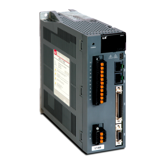
Page 187: Outline Drawing
7. Product Specifications 7.2.2 Outline Drawing L7□A001□ - L7□A004□ 109.7 172.5 ★ Weight: 1.2 [kg] L7□A008□ / L7□A010□ ★ Weight: 1.5 [kg] (cooling fan included) 7-25... - Page 188 7. Product Specifications L7□A020□ / L7□A035□ ★ Weight: 2.5 [kg] (cooling fan included) 7-26...
-
Page 189: Options And Peripheral Devices
7. Product Specifications Options and Peripheral Devices ■ Option (incremental encoder cable) Product Type Name Applicable Category Specifications Name (Note 1) Motors Motor connection Drive connection (CN2) All models Quadrature type APM-SA, Incremental APM-SB, APCS- 1. Motor connection signaling Encoder cable APM-SC a. - Page 190 7. Product Specifications ■ Option (serial encoder cable) Type Name Product Applicable Category Specifications Name Motors (Note 1) Drive connection (CN2) Motor connection All models of APM-SA, Serial type APM-SB, Encoder APCS- 1. Motor connection cable APM-SC signaling a. Cap specifications (9 positions): 172161-1 (AMP) (small capacity) b.
- Page 191 7. Product Specifications ■ Option (power cable) Category Product Type Name Applicable Specifications Name (Note 1) Motors Motor connection Drive connection All models APM-SA, 1. Motor connection APM-SB, a. Cap specifications (4 positions): 172159-1 (AMP) Standard type APCS- For power APM-SC b.
- Page 192 7. Product Specifications Category Product Type Name Applicable Specifications Name (Note 1) Motors Motor connection Drive connection All models Standard type APM-SE APCS- For power 1. Motor connection (MS: Military Standard) Power cable a. Plug specifications: MS3108B (MS3106B) 20-4S APM-HE 2.
- Page 193 7. Product Specifications Category Product Type Name Applicable Specifications Name (Note 1) Motors Motor connection Drive connection All models Brake cable APM-FB for flat type APCS- 5. Motor connection For power motor(small g. Plug specifications: JN4FT02SJ1-R(JAE) capacity) APM-FC h. Socket specifications: ST-TMH-S-C1B(JAE) Series 6.
- Page 194 Name Drive [Upper level controller] [Drive connection CN1] Pin number display signali CN1 Cable APC-CN1 A L7 SERIES 1. Drive connection (CN1) a. Case specifications: 10350-52A0-008 (3M) b. Connector specifications: 10150-3000VE (3M) c. Cable specifications: ROW-SB0.1Cx50C (AWG 28) [Servo drive – CN5] [PC - USB port] 1.
- Page 195 Type Name Applicable Specifications Name Drive APC-VSCN1T Terminal block L7 SERIES for CN1 APC-VPCN1T 1. APC-VSCN1T: CN1 T/B expansion of APD-VS 2. APC-VPCN1T: CN1 T/B expansion of APD-VP 3. The cable length can be changed. 4. Standard cable length: 0.5 [m]...
- Page 196 7. Product Specifications ■ Option (braking resistance) Categ Product Type Name Applicable Specifications Name Drive L7□A001□ Resist Braking APC-140R50 L7□A002□ ance resistance L7□A004□ L7□A008□ Resist Braking APC-300R30 ance resistance L7□A010□ L7□A035□ Resist (2P) Braking ance APC-600R30 resistance L7□A035□ (3P) 7-34...
-
Page 197: Maintenance And Inspection
8. Maintenance and Inspection Maintenance and Inspection Maintenance and Inspection This chapter explains how to conduct basic maintenance and inspection, diagnosis and troubleshooting on the servo motor and drive. 8.1.1 Precautions 1. Measuring motor voltage: The voltage output from the servo amp to the motor is PWM controlled, and, for this reason, its waves take the form of pulses. -
Page 198: Parts Replacement Cycle
8. Maintenance and Inspection (2) Servo Drive Inspection Inspection What to do if abnormality is Inspection Period How to inspect Item found Cleaning of the Check if there is any dust or Clean with air pressure or main body and At least once a year oil on it. -
Page 199: Diagnosis Of Abnormality And Troubleshooting
8. Maintenance and Inspection Diagnosis of Abnormality and Troubleshooting AL- is displayed if a problem occurs during operation. In this case, try to solve the problem by following this advice. If the problem persists, contact our service center. 8.2.1 Servo Motor [Cause of abnormality, how to inspect, and troubleshooting] Symptoms Cause... -
Page 200: Servo Drive
8. Maintenance and Inspection 8.2.2 Servo Drive If an alarm triggers, the malfunction signal output contact (ALARM) is turned off and the dynamic brake stops the motor. Alarm Name Details What to inspect Code Check for incorrect drive output wiring / incorrect encoder wiring. - Page 201 8. Maintenance and Inspection Alarm Name Details What to inspect Code Check regenerative resistance. RST power fail Main power failure Check power unit wiring and power. Control power fail Control power failure Check power unit wiring and power. Check the encoder, encoder setting, encoder Over speed limit Overspeed wiring, gain setting, motor wiring, motor ID,...
- Page 202 8. Maintenance and Inspection Servo Drive Overload Graphs (400W or below) (1) Graph of Overload during Rotation AL-21 AL-21 Load (%) Occurring Load (%) Occurring Time (sec) Time (sec) 100% or Infinite below 55776.0 89241.6 33465.6 66.8 106.9 40.08 13944.0 22310.4 8366.4...
- Page 203 8. Maintenance and Inspection (2) Graph of Overload during Stop AL-21 AL-21 Load (%) Occurring Load (%) Occurring Time (sec) Time (sec) 100% or Infinite below 37937.7 60700.3 22762.62 50.1 80.2 30.06 9483.9 15174.2 5690.34 38.5 61.6 23.1 4215.1 6744.2 2529.06 30.3 48.5...
- Page 204 8. Maintenance and Inspection Servo Drive Overload Graphs (SA type of 100 W or below) (1) Graph of Overload during Rotation AL-21 AL-21 Load (%) Occurring Load (%) Occurring Time (sec) Time (sec) 100% or Infinite below 1696.0 2713.6 1017.6 3.12 424.0...
- Page 205 8. Maintenance and Inspection (2) Graph of Overload during Stop AL-21 AL-21 Load (%) Occurring Load (%) Occurring Time (sec) Time (sec) 100% or Infinite below 1372.8 2196.5 823.68 2.34 343.2 549.1 205.92 2.04 152.5 244.0 91.518 85.8 137.3 51.48 1.56 58.6 93.8...
- Page 206 8. Maintenance and Inspection Servo Drive Overload Graphs (750W, 1.0KW) (1) Graph of Overload during Rotation AL-21 AL-21 Occurrin Occurrin Load (%) Load (%) g Time g Time (sec) (sec) 100% or Infinite below 105800 169280.0 63480 119.0 190.4 71.4 26450 42320.0...
- Page 207 8. Maintenance and Inspection (2) Graph of Overload during Stop AL-21 AL-21 Occurrin Occurrin Load (%) Load (%) g Time g Time (sec) (sec) 100% or Infinite below 72512.0 116019.2 43507.2 93.4 149.4 56.04 18128.0 29004.8 10876.8 71.8 114.9 43.08 8056.9 12891.0 4834.14...
- Page 208 8. Maintenance and Inspection Servo Drive Overload Graphs (2.0KW, 3.5kW) (1) Graph of Overload during Rotation AL-21 AL-21 Load(%) Occurring Load(%) Occurring Time(sec) Time(sec) 100% or Infinite below 4832.0 7731.2 2899.2 66.8 106.9 40.08 1208.0 1932.8 724.8 50.1 80.2 30.06 536.9 859.0...
- Page 209 8. Maintenance and Inspection (2) Graph of Overload during Stop AL-21 AL-21 Load(%) Occurring Load(%) Occurring Time (sec) Time (sec) 100% or Infinite below 7536.0 12057.6 4521.6 44.0 70.4 26.4 1884.0 3014.4 1130.4 36.0 57.6 21.6 837.3 1339.7 502.38 30.3 48.5 18.18 471.0...
- Page 210 8. Maintenance and Inspection 8-14...
-
Page 211: Appendix
9. Appendix Appendix... -
Page 212: Motor Type And Id (To Be Continued On The Next Page)
9. Appendix Motor Type and ID (to be continued on the next page) Model Name Watt Notes Model Name Watt Notes SAR3A SE15D 1500 Custom-made SAR5A SC20B(D2) 2000 SA01A SA015A SE09A SBN01A SE15A 1500 SBN02A SE22A 2200 SBN04A SE30A 3000 SE06D SBN04A-BK SE11D... - Page 213 9. Appendix Model Name Watt Notes Model Name Watt Notes SF20G 1800 DB03D LF30G 2900 DB06D SF44G 4400 DB09D SF60G 6000 DC06D Specifically for HC05H DC12D 1200 customers DC18D 1800 SE35D 3500 For DS only DD12D 1200 SE30D 3000 Custom-made DD22D 2200 SF44ML...
-
Page 214: Test Drive Procedure
9. Appendix Test Drive Procedure Thank you for purchasing our product. Conduct test drive following the process described as follows: Caution In order to prevent accidents, conduct an operation test and test drive in manual JOG operation when there is no load (the motor exists without any coupling or belt) after attaching the servo motor to your equipment. - Page 215 9. Appendix 4. Control power supply: Supply single-phase AC 220 [V] to C1 and C2. Be sure to check external input voltage before turning on the servo drive. Check whether the display is normal. (There should be no break on the seven segments or alarm output.) 5.
- Page 216 9. Appendix 7. Test drive: Start [Cn-00] by pressing [SET] to conduct test drive manually. (JOG operation speed can be changed in [P3-12].) * [Up]: Motor forward rotation (CCW) → Only operate while you hold down the key. * [Down]: Reverse motor rotation (CW) →...
- Page 217 9. Appendix 10-1 How to Set Control Parameters [Gain Tuning] 1) Auto gain tuning → Perform automatic gain tuning by pressing [SET] in [Cn-05]. → If the load condition of the equipment is not directly related to motor shaft, it is hard to perform accurate gain tuning because of characteristics of automatic gain tuning.
- Page 218 9. Appendix...
-
Page 219: Quality Assurance
Address Phone This product was produced under strict quality control and test procedures of LS Mecapion technicians. Its term of warranty is 12 months after the date of installation. If no date of installation is written, the warranty is valid for 18 months after the date of manufacture. However, this term of warranty may change depending on contract terms. -
Page 220: User Manual Revision History
2012.04.09 correct minor typo Product Disposal Green Management The LS Mecapion servo drive is LS Mecapion considers environment environmentally friendly. protection as a high priority of management, and its employees try their It can be broken down to iron, aluminum, best to protect the Earth.
Need help?
Do you have a question about the L7 Series and is the answer not in the manual?
Questions and answers