Sign In
Upload
Manuals
Brands
LS ELECTRIC Manuals
Inverter
G100
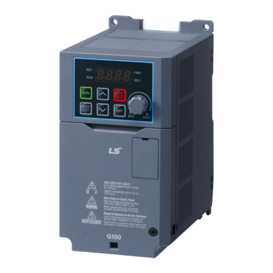
LS ELECTRIC G100 Manuals
Manuals and User Guides for LS ELECTRIC G100. We have
3
LS ELECTRIC G100 manuals available for free PDF download: Manual, Troubleshooting Manual
LS ELECTRIC G100 Manual (419 pages)
Brand:
LS ELECTRIC
| Category:
Inverter
| Size: 11 MB
Table of Contents
Safety Information
2
Quick Reference Table
5
Table of Contents
6
Preparing the Installation
15
Product Identification
15
Part Names
17
Installation Considerations
21
Selecting the Installation Site
22
Cable Selection
26
Installing the Inverter
29
Mount on the Wall or Within the Panel
31
Wiring
34
Post-Installation Checklist
60
Test Run
62
Learning to Perform Basic Operations
65
About the Keypad
65
About the Display
66
Operation Keys
67
Control Menu
68
Learning to Use the Keypad
68
Group and Code Selection
69
Navigating Directly to Different Codes (Jump Codes)
70
Setting Parameter Values
71
Actual Application Examples
72
Acceleration Time Configuration
72
Frequency Reference Configuration
73
Jog Frequency Configuration
74
Parameter Initialization
75
Frequency Setting (Keypad) and Operation (Via Terminal Input)
76
Frequency Setting (Potentiometer) and Operation (Terminal Input)
77
Frequency Setting with (Internal) Potentiometer and Operation Command with the Keypad [RUN] Key
79
Monitoring the Operation
81
Output Current Monitoring
81
Trip Condition Monitor
82
Learning Basic Features
85
Frequency Reference Configuration
88
Set the Operation Frequency from the Keypad - Direct Input
88
Set the Operation Frequency from the Keypad - Using [▲] and [▼] Keys
89
V1 Terminal as the Source
89
V2 Terminal as the Source
95
Built-In Volume Input (V0) as the Source
101
Setting a Reference Frequency Using Input Current (I2)
101
Frequency Reference Source Configuration for
103
Communication
103
Frequency Hold by Analog Input
103
Multi-Step Frequency Configuration
104
Command Source Configuration
106
The Keypad as a Command Input Device
106
Terminal Block as a Command Input Device (Fwd/Rev Run Commands)
106
Terminal Block as a Command Input Device (Run and Rotation Direction Commands)
107
Communication as a Command Input Device
108
Forward or Reverse Run Prevention
108
Power-On Run
109
Reset and Restart
110
Setting Acceleration and Deceleration Times
111
Acc/Dec Time Based on Maximum Frequency
111
Acc/Dec Time Based on Operation Frequency
112
Multi-Step Acc/Dec Time Configuration
113
Acc/Dec Time Switch Frequency
115
Acc/Dec Pattern Configuration
116
Stopping the Acc/Dec Operation
118
V/F Control
118
Linear V/F Pattern Operation
118
Square Reduction V/F Pattern Operation
119
User V/F Pattern Operation
120
Torque Boost
122
Manual Torque Boost
122
Auto Torque Boost
123
Motor Output Voltage Adjustment
124
Start Mode Setting
124
Accelerating Start
124
DC Braking after Start
125
Initial Excitation of Stop Status (Pre-Excite)
126
Stop Mode Setting
126
Deceleration Stop
126
DC Braking after Stop
127
Free Run Stop
128
Power Braking
129
Frequency Limit
129
Frequency Limit Using Maximum Frequency and Start Frequency
129
Frequency Limit Using Upper and Lower Limit Frequency Values
130
Frequency Jump
131
Operation Mode
132
Multi-Function Input Terminal Control
133
Fire Mode Operation
134
User Sequence Settings
136
Learning Advanced Features
145
Operating with Auxiliary References
147
Jog Operation
151
Jog Operation 1-Forward
151
Jog Operation 2-Fwd/Rev Jog by Multi-Function Terminal
152
Up-Down Operation
153
3-Wire Operation
156
Safe Operation Mode
158
Dwell Operation
159
Slip Compensation Operation
161
PID Control
162
Basic PID Operation
163
Pre-PID Operation
167
PID Operation Sleep Mode
168
PID Switching (PID Openloop)
169
Auto-Tuning
169
Sensorless Vector Control for Induction Motors
172
Sensorless Vector Control Operation Setting for Induction Motors
174
Sensorless Vector Control Operation Guide for Induction Motors
177
Energy Buffering Operation (Kinetic Energy Buffering)
179
Energy Saving Operation
183
Manual Energy Saving Operation
183
Automatic Energy Saving Operation
183
Speed Search Operation
184
Auto Restart Settings
188
Operational Noise Settings (Change of Carrier Frequency Settings)
189
Nd Motor Operation
191
Commercial Power Source Transition
192
Cooling Fan Control
193
Input Power Frequency and Voltage Settings
194
Parameter Save
194
Parameter Initialization
195
Parameter Lock
196
Changed Parameter Display
197
Timer Settings
197
Brake Control
198
Multi-Function Relay On/Off Control
200
Press Regeneration Prevention
201
Analog Output
203
Voltage Analog Output
203
Current Analog Output
206
Digital Output
208
Multi-Function Relay Settings
208
Trip Output to Multi-Function Relay
213
Multi-Function Relay Terminal Delay Time Settings
214
Base Block
215
Overvoltage Trip(OVT) Suppression
216
Setting the Output Overcurrent Suppression Method
217
Prevention of Output Current Hunting
217
Learning Protection Features
219
Motor Protection
219
Electronic Thermal Motor Overheating Prevention (ETH)
219
Motor Temperature Sensing
221
Overload Early Warning and Trip
224
Stall Prevention and Flux Braking
226
Inverter and Sequence Protection
231
Input/Output Open-Phase Protection
231
External Trip Signal
232
Inverter Overload Protection
233
Speed Command Loss
233
Dynamic Braking (DB) Resistor Configuration
235
Under Load Fault Trip and Warning
238
Fan Fault Detection
240
Lifetime Diagnosis of Components
241
Low Voltage Fault Trip
242
Output Block by Multi-Function Terminal
242
Trip Status Reset
243
Inverter Diagnosis State
243
Operation Mode on Option Card Trip
243
No Motor Trip
244
Low Voltage Trip 2
245
Inverter Pre-Overheat Warning
245
Torque Detection Protection Action
246
Fault/Warning List
248
Communication Features
251
Communication Standards
251
Communication System Configuration
253
Communication Line Connection
253
Setting Communication Parameters
254
Setting Operation Command and Frequency
255
Command Loss Protective Operation
256
Setting IDLE Mode Behavior
257
Setting Virtual Multi-Function Input
258
Saving Parameters Defined by Communication
258
Total Memory Map for Communication
259
Parameter Group for Data Transmission
259
Communication Protocol
260
LS INV 485 Protocol
260
Modbus-RTU Protocol
266
Driveview9
269
Compatible Common Area Parameter
272
G100 Expansion Common Area Parameter
275
Monitoring Area Parameter (Read Only)
275
Control Area Parameter (Read/ Write)
280
Memory Control Area Parameter (Read and Write)
282
Table of Functions
285
Operation Group
285
Drive Group (Par→Dr)
286
Basic Function Group (Par→Ba)
290
Expanded Function Group (Par→Ad)
294
Control Function Group (Par→Cn)
300
Input Terminal Block Function Group (Par→In)
304
Output Terminal Block Function Group (PAR→OU)
309
Communication Function Group (PAR→CM)
314
Application Function Group (PAR→AP)
319
Protection Function Group (Par→Pr)
322
2Nd Motor Function Group (PAR→M2)
327
User Sequence Group(PAR→US)
329
User Sequence Function Group(PAR→UF)
332
Troubleshooting
353
Trip and Warning
353
Fault Trips
354
Warning Messages
358
Troubleshooting Fault Trips
359
Other Faults
361
Maintenance
367
Regular Inspection Lists
367
Daily Inspections
367
Annual Inspections
369
Bi-Annual Inspections
370
Storage and Disposal
371
Storage
371
Disposal
371
Technical Specification
373
Input and Output Specification
373
Product Specification Details
377
External Dimensions
380
Peripheral Devices
391
Fuse and Reactor Specifications
392
Terminal Screw Specification
394
Braking Resistor Specification
395
Continuous Rated Current Derating
397
Heat Emission
401
Remote Keypad Option
402
External Filters
404
Safety Function STO (Safe Torque Off)
405
Safety Standards
405
Safety Features Description
406
Safety Operation Description
407
Product Warranty
408
Manual Revision History
411
Index
412
Advertisement
LS ELECTRIC G100 Troubleshooting Manual (41 pages)
AC Variable Speed Drive 0.4-7.5kW, 200V,400V
Brand:
LS ELECTRIC
| Category:
Inverter
| Size: 1 MB
Table of Contents
Table of Contents
3
Introduction
4
Product Identification
5
Association Manual
5
Safety Information
6
Revision Record
8
Basic Checklist
9
Before You Think It Failed
9
Basic Operations
11
Change Parameter
13
Change Carrier Frequency
13
Monitor Fault Trip
15
Troubleshooting
17
Trips and Warnings
17
Failure/Warning List
18
Troubleshooting Fault Trips
21
Troubleshooting Other Faults
27
Maintenance
33
Regular Inspection List
33
Daily Inspections
33
Annual Inspections
34
Bi-Annual Inspections
35
Check Input/Output Module
36
Replace Cooling Fan
39
Storage and Disposal
41
Storage
41
Disposal
41
LS ELECTRIC G100 Manual (25 pages)
Brand:
LS ELECTRIC
| Category:
Control Unit
| Size: 0 MB
Table of Contents
Table of Contents
3
1 Overview
5
What Is the PROFIBUS-DP Communication Module
5
Package Content
5
2 LSLV-G100 PROFIBUS-DP Communication Module
6
Technical Specifications
6
PROFIBUS-DP Communication Module Layout
7
PROFIBUS-DP Connector Specifications
8
Installation
9
Network Cable Specifications
11
Network Cable Length by Baud Rate
11
3 Operation Status and LED Indicators
12
LED Indicators
12
Device Status by Indicator Signal
13
4 Inverter Parameters
15
PROFIBUS-DP Communication Parameter List
15
PROFIBUS-DP Communication Parameters
16
Communication Module Version
16
Station ID Setting
16
LED Indication for Communication Status
17
Number of para Status Settings
18
Para Status 1-8
19
Number of para Control Settings
20
Para Control 1-8
21
Comm Update
22
Setting PROFIBUS Bit Swap
22
5 GSD File (Electronic Data Sheets)
23
Advertisement
Advertisement
Related Products
LS ELECTRIC GOL-RR8T
LS ELECTRIC LSLV-S100 Series
LS ELECTRIC LSLV0001M100-1E0FNS
LS ELECTRIC LSLV0002M100-1E0FNS
LS ELECTRIC LSLV0004M100-1E0FNS
LS ELECTRIC LSLV0004S100-1 Series
LS ELECTRIC LSLV0004S100-2 Series
LS ELECTRIC LSLV0004S100-4 Series
LS ELECTRIC LSLV0008M100-1E0FNS
LS ELECTRIC LSLV0008S100-1 Series
LS ELECTRIC Categories
Controller
Control Unit
DC Drives
Servo Drives
Inverter
More LS ELECTRIC Manuals
Login
Sign In
OR
Sign in with Facebook
Sign in with Google
Upload manual
Upload from disk
Upload from URL