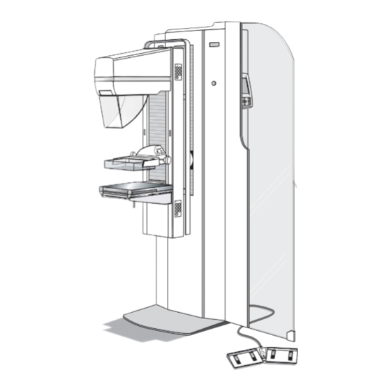
Sign In
Upload
Manuals
Brands
LORAD Manuals
Medical Equipment
AFFINITY Series
LORAD AFFINITY Series Mammography Machine Manuals
Manuals and User Guides for LORAD AFFINITY Series Mammography Machine. We have
1
LORAD AFFINITY Series Mammography Machine manual available for free PDF download: Service Manual
LORAD AFFINITY Series Service Manual (215 pages)
Mammography Systems
Brand:
LORAD
| Category:
Medical Equipment
| Size: 5.14 MB
Table of Contents
Chapter 1: General Information
21
Required Tools and Equipment
22
Interlocks
23
Radiation Safety
24
Unit Description
25
Figure 1-2 Affinity Gantry and C-Arm
26
Control Panel
27
Compliance Data
28
Certifiable Components
29
Location of Labels
30
Chapter 2: System Installation
31
Unpacking Instructions
32
Unit Installation
34
Power Cable Connection
35
Remote X-Ray On/Power on Light Connection
36
Control Panel Remote Location Installation
37
Securing Unit in Position
38
Dual Function Footswitch(Es)
39
Connecting Film Labeling Devices
40
Initial Power up
41
Installing the Radiation Shield
42
Chapter 3: Functional Checks/Setting Defaults
43
System Power up
44
Post Power-Up Checks
45
Table 3-1 Post Power-Up Checks
46
Figure 3-3 Dual Function Footswitch
47
Figure 3-4 Emergency off
48
Figure 3-5 the Tubehead Controls
49
The Affinity Series Control Panel
50
Control Panel Screens
51
Figure 3-9 the Exposure Default Screen
52
Figure 3-11 Calibration Screen #1—Calibration Mode
53
Figure 3-13 Calibration Screen #3—Calibration Mode
54
Setting User Defaults
55
Chapter 4: Calibrations and Performance Checks
57
Entering Calibration Mode
58
Table 4-2 the Calibration Screens
59
Compression System Calibration Procedures
63
Compression Thickness Calibration
64
Exposure System Calibration
65
Figure 4-3 High Voltage Generator Calibration Setup
66
Check Ma Calibration
67
Figure 4-4 Example—Filament Waveforms Pattern
68
Table 4-3 Filament Waveforms Amplitude
70
Backup Timer Test
71
Automatic Exposure Control System Calibration
72
AEC Detector Gain Calibration
73
AEC Detect Board—R1 Adjustment
74
Kv Tracking—Large Focal Spot (Mo)
75
Initial Calibration—Large Focal Spot (Rh)
76
Kv Tracking—Large Focal Spot (Rh)
77
Performance Test—Large Focal Spot (Rh)
78
Initial Calibration—Small Focal Spot (Mo)
79
Kv Tracking - Small Focal Spot (Mo)
80
Starting AEC Values - Small Focal Spot
81
Performance Test - Small Spot (Rh)
82
HTC Factor (Offset) Calibration
83
Compression Thickness Threshold Adjustment
84
Table 4-12 Compression Thickness Threshold Semi-Log
86
C-Arm Safety Function Check
87
Performance Checks
88
Figure 4-6 Half-Value Layer Setup
89
Table 4-13 Half-Value Layer Semi-Log
90
Reproducibility and Linearity in Manual Mode
91
Reproducibility in Auto-Time Mode
92
Table 4-14 Reproducibility Worksheet
94
Table 4-15 Linearity Worksheet
95
Bucky Device Performance Check
96
System Level Functional Check
97
X-Ray Tubehead Leakage Check
98
Figure 4-9 Tubehead Shielding Check
99
X-Ray and Light Field Check and Alignment Procedures
100
Exposing and Viewing the X-Ray Field
101
Aperture Adjustment Procedures
102
Auto Aperture Alignment
103
Align the 18 X 24 CM Large Focal Spot
104
Figure 4-13 Auto Aperture Alignment—18 X 24 CM Large Focal Spot
105
Magnification Full Field (18 X 24 CM) Aperture Alignment (SM FS)
106
CM Spot Contact Aperture Alignment (LG FS)
107
Light Field Edge Contrast Check
109
Figure 4-15 Light Field Edge Contrast Check
110
Light Field Illuminance Check
111
Mechanical Adjustments
112
Compression Display Potentiometer Adjustment
113
C-Arm Safety Microprocessor Board Calibration/Vertical Drive Force Load Cell Setting
114
Maintenance Procedures
115
Chapter 5: Maintenance—General
117
Troubleshooting
118
Power Distribution
119
Tubehead Functions
120
Mechanical Functions
121
Exposure Control
122
Automatic Exposure Control
123
Alert Codes Log
124
System Data Retrieval
126
Downloading Alert Codes Log
127
Uploading Calibration Data
128
Chapter 6: Maintenance—Remove and Replace Procedures
129
Figure 6-1 Gantry Components
130
Removing Covers and Panels from the Gantry
131
Left and Right Side Panels
132
Rear Connector Panel
133
Gantry Cover Components
134
Emergency off Switches
135
Control Panel Components
136
Display Microprocessor Board
137
Left-Side Gantry Components
138
Figure 6-7 HV Generator Assembly (Old Style Mounting Plate)—Removal
140
Figure 6-8 HV Generator Assembly (New Style Mounting Plate)—Removal
143
Power Control Board
144
Right-Side Gantry Components
145
Firmware Replacement
146
Low Voltage Power Supply
147
Internal Gantry Components
148
The C-Arm Angle Detent Microswitch
149
The C-Arm Rotation Potentiometer
150
The C-Arm Vertical Drive Actuator
151
Figure 6-14 Components of the Vertical Drive Assembly
152
C-Arm Components—Remove and Replace
154
Figure 6-16 Tubehead / Beam Limiting Components
155
Figure 6-17 Compression Device Components
156
C-Arm Frame Components
157
C-Arm Frame Covers
158
Figure 6-20 C-Arm Frame Covers
159
Filament Protection Board
160
Position Switch Board
161
C-Arm Switch Interface Board
162
Tubehead Components
163
X-Ray Tube
164
Tubehead Control Board
166
Table 6-1 Tubehead Control Board Push Button Switches
167
C-Arm Cooling Fan
168
Beam Limiting Assembly
169
Filter Shifter Assembly
170
Light Field Lamp Assembly with Fan
171
Light Field Lamp Assembly—Lamp Replacement
172
Motorized Mirror Assembly
173
Compression Assembly
174
Figure 6-32 Compression Motor & Brake Assembly—Removal
175
Compression Clutch & Clutch Brake Assembly
176
Figure 6-33 Compression Clutch & Clutch Brake Assembly—Removal
177
Compression / AEC Position Display Boards
178
Compression Thickness Potentiometer
179
Figure 6-35 Removal of Timing Belt from Upper Block Assembly
180
Figure 6-36 Removal of Timing Belt from Bearing Block Assembly
181
IRSD Components
182
AEC Detector Assembly
183
AEC Position Detect Board
184
Accessory Detect Board
185
Chapter 7: Parts List
187
Table 7-2 Gantry Left and Right-Side Components—Parts List
188
Table 7-5 C-Arm Compression Device Components—Parts List
189
Table 7-7 Miscellaneous—Parts List
190
Appendix A: Specifications
191
Operating Environment
192
C-Arm Specifications
193
Compression Paddles
194
Apertures
195
Image Receptor Support Device
196
High Voltage Generator Specification (in Compliance with IEC 601-2-7)
198
Table A-1 Kv Versus Ma Table
199
Image Receptors
200
Modes of Operation
201
Room Requirements
202
Appendix B: Technical References
203
Table B-2 Power Control Board (PN 1-003-0445) Test Points
204
Table B-4 Display Microprocessor Board (PN 1-003-0428) Test Points
205
Table B-7 AEC Position Compression Display (PN 1-003-0472) Test Points
206
Table B-11 HV Control Filament Board (PN 1-003-0485) Test Points
207
LED Indicators
208
Table B-14 C-Arm Safety Board (PN 1-003-0440) LED Indicators
209
Image Receptor Detect Board—Sensor Combinations
210
Fuses
211
Table B-20 Affinity Series Fuses
212
Jumpers
213
Table B-24 HV Control Filament Board (PN 1-003-0485) Jumper Settings
214
Advertisement
Advertisement
Related Products
LORAD Categories
Medical Equipment
More LORAD Manuals
Login
Sign In
OR
Sign in with Facebook
Sign in with Google
Upload manual
Upload from disk
Upload from URL