Table of Contents
Advertisement
Quick Links
Artwork and Signature File for:
9-500-0255 MANUAL, AFFINITY SERVICE
Artwork consists of:
REV AUTHORED BY
A. TAMBASCIO
7/24/2003
REV DRAFTED BY
BILL MOSES
8/5/2003
PROPRIETARY: This document contains
proprietary data of Hologic, Inc. No
disclosure, reproduction or use of any
part thereof may be made except by
written permission from Hologic.
REV. RELEASE DATE:
3
•
Two hundred and twelve (212) 8 ½ inch x 11 inch pages.
DATE
DATE
TITLE
MANUAL, AFFINITY
SERVICE
8/14/03
Osteoporosis Assessment
LORAD
DirectRay
FLUOROSCAN
ARTWORK
Breast Cancer Detection
©
Digital Imaging
©
C-arm Imaging
©
DOCUMENT NUMBER
AW-00227
SIZE A
REV
005
SHEET 1 OF 1
Form ENG-0034-T03, Rev. 001
Advertisement
Table of Contents

Summary of Contents for LORAD AFFINITY Series
- Page 1 Artwork and Signature File for: 9-500-0255 MANUAL, AFFINITY SERVICE Artwork consists of: • Two hundred and twelve (212) 8 ½ inch x 11 inch pages. Osteoporosis Assessment REV AUTHORED BY DATE LORAD Breast Cancer Detection © A. TAMBASCIO 7/24/2003 DirectRay Digital Imaging ©...
- Page 5 Service Manual for Affinity Series Mammography Systems Part Number 9-500-0255 Revision 005...
- Page 7 Service Manual Table of Contents List of Figures ..................... -vii List of Tables ....................... -ix Preface ......................P-xi 1.0 Using the Service Manual ..................... P-xi 1.1 Warnings, Cautions and Notes ..................P-xii 2.0 Acronym List ........................P-xii Chapter 1: General Information ................. 1-1 1.0 Introduction ...........................
- Page 8 2.0 System Power Up ........................3-2 2.1 Pre-Power Up Checks ......................3-2 2.2 Power Up Sequence ......................3-2 2.3 Post Power-Up Checks .....................3-3 3.0 The Affinity Series Control Panel ....................3-8 3.1 Control Panel Screens ......................3-9 4.0 Setting User Defaults ......................3-13 5.0 Setting Exposure Technique Defaults ..................3-13...
- Page 9 Service Manual Chapter 4: Calibrations and Performance Checks ..........4-1 1.0 Introduction ........................... 4-1 2.0 Calibration Procedures ......................4-1 2.1 Entering Calibration Mode ....................4-2 3.0 Compression System Calibration Procedures ................4-7 3.1 Compression Force Calibration ..................4-7 3.2 Compression Thickness Calibration ................. 4-8 4.0 Exposure System Calibration ....................
- Page 10 Service Manual 7.0 X-ray and Light Field Check and Alignment Procedures ............4-44 7.1 X-ray Beam Alignment Template ..................4-44 7.2 Exposing and Viewing the X-ray Field ................4-45 7.3 Aperture Adjustment Procedures ..................4-46 7.4 Auto Aperture Alignment ....................4-47 7.4.1 Align the 24 x 30 cm Large Focal Spot ..............4-47 7.4.2 Align the 18 x 24 cm Large Focal Spot ..............4-48 7.5 Magnification Full Field (18 x 24 cm) Aperture Alignment (SM FS) .........4-50 7.6 10 cm Coned-down Contact Aperture Alignment (LG FS) ..........4-50...
- Page 11 Service Manual Chapter 6: Maintenance—Remove and Replace Procedures ......6-1 1.0 Introduction ..........................6-1 2.0 Gantry Components—Remove and Replace ................6-1 2.1 Removing Covers and Panels From the Gantry ..............6-3 2.1.1 Left and Right Side Panels ..................6-4 2.1.2 Upper Rear Gantry Panel ..................6-4 2.1.3 Rear Connector Panel ....................6-5 2.1.4 Lower Rear Panel/Power Distribution Assembly ............6-5 2.2 Gantry Cover Components ....................6-6...
- Page 12 Service Manual 3.3 Compression Assembly ....................6-46 3.3.1 Compression Device Covers ................... 6-46 3.3.2 Compression Motor & Brake Assembly ..............6-46 3.3.3 Compression Clutch & Clutch Brake Assembly ............6-48 3.3.4 Compression / AEC Position Display Boards ............6-50 3.3.5 Compression Tray Sensor Board ................6-50 3.3.6 Compression Thickness Potentiometer ..............
- Page 13 List of Figures Figure 1-1 The Affinity System .......................1-1 Figure 1-2 Affinity Gantry and C-Arm ....................1-6 Figure 1-3 Affinity Series Control Panel ..................1-7 Figure 1-4 Compliance Label Locations..................1-10 Figure 2-1 Example Room Layout ....................2-1 Figure 2-2 Un-Crating the Gantry ....................2-2 Figure 2-3 Isolation Transformer Taps....................2-5...
- Page 14 Service Manual List of Figures Figure 6-2 Gantry Components—Covers and Panels ..............6-3 Figure 6-3 Rear Connector and Lower Rear Panels—Removal............6-5 Figure 6-4 C-arm Angle Display Board—Removal................. 6-6 Figure 6-5 Emergency Off Switch—Removal................. 6-7 Figure 6-6 Control Panel Components ..................6-8 Figure 6-7 HV Generator Assembly (old style mounting plate)—Removal ........
- Page 15 Table 4-14 Reproducibility Worksheet ..................4-38 Table 4-15 Linearity Worksheet ....................4-39 Table 5-1 Affinity Recommended Preventive Maintenance Procedures ........5-2 Table 5-2 Affinity Series Alert Messages ..................5-8 Table 5-3 Null-Modem, 9-pin to 25-pin Adapter Connections ...........5-10 Table 6-1 Tubehead Control Board Push Button Switches............6-39 Table 7-1 Gantry Cover, Control Panel and Internal Components—Parts List ......7-1...
- Page 16 Table B-18 HV Control Filament Board (PN 1-003-0485) LED Indicators ........B-8 Table B-19 Image Receptor Sensor Combinations ............... B-8 Table B-20 Affinity Series Fuses ....................B-10 Table B-21 Microprocessor Board (PN 1-003-0493) Jumper Settings ......... B-11 Table B-22 Communications Interface Board (PN 1-003-0434) Jumper Settings ......B-11 Table B-23 C-Arm Safety Board (PN 1-003-0440) Jumper Settings ..........
- Page 17 The first four sections of this service manual are designed to provide a service engineer with a sequence for setting up and calibrating the Affinity Series Mammography Systems (Affinity and Affinity Platinum). The remaining sections detail the maintenance procedures (i.e., performance checks, adjustments, and removal and replacement), replacement parts and specifications.
- Page 18 Notes indicate important information that must be followed to ensure the proper operation of the system. Acronym List Table P-1 provides a list of the common Acronyms used throughout the Affinity Series Service Manual. Table P-1: List of Acronyms for Affinity...
- Page 19 Service Manual Preface Acronym List Table P-1: List of Acronyms for Affinity Acronym Definition IRSD Image Receptor Support Device Pound(s) LVPS Low Voltage Power Supply milli-Amps Magnification Mode maximum milli-Gray minimum millimeters Molybdenum MQSA Mammography Quality Standards Act mrad milli-Radiation Absorbed Dose Newtons Optical Density printed circuit board...
- Page 20 Service Manual Preface Acronym List P/N 9-500-0255...
-
Page 21: Chapter 1: General Information
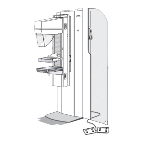
Service Manual Chapter 1: General Information Introduction Chapter 1: General Information Introduction The L Affinity is a dedicated mammography system which features automatic and ORAD manual exposure modes, a compact control panel, and optional film labeling abilities (Figure 1-1). Intended Uses The unit is intended to function in screening and diagnostic mammography procedures. -
Page 22: Required Tools And Equipment
Service Manual Chapter 1: General Information Safety Required Tools and Equipment Table 1-1 identifies the required tools and equipment for use during installation and maintenance of the Affinity System. Table 1-1: Required Tools and Equipment for Installation and Maintenance • Standard Hand Tools (non-metric) •... -
Page 23: Interlocks
Interlocks In addition to the Emergency OFF switches, the Affinity Series contains several safety interlocks. These interlocks are as follows: • C-arm Movement Interlock - When the C-arm encounters an obstruction during travel, this interlock engages to immediately stop vertical travel and disable all C- arm vertical movements (except C-arm UP) until the obstruction is cleared. -
Page 24: Radiation Safety
Service Manual Chapter 1: General Information Safety • Automatic compression release (decompression) is disabled when a localization paddle is installed. • C-arm Force Limit is reached. The downward motorized movement of the C-arm is limited to a force of 154 N, +44 N (35 lb, +10 lb). Radiation Safety The unit’s radiation safety is designed to comply with all requirements of 21CFR Part 1020, IEC 601-2-7, and IEC 601-1-3. -
Page 25: Unit Description
Service Manual Chapter 1: General Information Unit Description Unit Description The three major hardware components of the Affinity Series are: • the Gantry • the C-arm • the Control Panel The following paragraphs briefly describe each of the major hardware components. -
Page 26: Figure 1-2 Affinity Gantry And C-Arm
Service Manual Chapter 1: General Information Unit Description Legend for Figure 1-2 1. Tubehead 2. 7-Button Keypad (total of four, two on each side) 3. 3-Button Keypad (not shown, located on Top of Tubehead) 4. Aperture Slot 5. Face Shield 6. -
Page 27: Control Panel
4. Exposure Parameter Selection Area 5. Message Area 6. Status Area 7. Function Keypad 8. Scroll Keys 9. Change Keys 10. Reset Key 11. Compression Release Key 12. Exposure Indicator 13. Exposure Enable Key Figure 1-3: Affinity Series Control Panel P/N 9-500-0255... -
Page 28: Compliance Data
Service Manual Chapter 1: General Information Compliance Data Compliance Data The Mammography System conforms to all applicable FDA regulations. Labels addressing the certifiable components are fixed to the unit at several points (refer to Figure 1-4). The main identification label containing the equipment model number and serial number is near the input power receptacle on the Gantry. -
Page 29: Certifiable Components
Service Manual Chapter 1: General Information Compliance Data Certifiable Components These components are identified using individual serial numbers in addition to the serial number of the overall L unit. ORAD Item Manufacturer X-ray Tube Varian (IM-113R) Beam Limiting Device ORAD High-Voltage Generator ORAD X-Ray Control... -
Page 30: Location Of Labels
Compliance Data Location of Labels Compliance labels and nameplates are positioned appropriately on the Affinity Series mammography unit. Nameplates contain the unit’s serial number and manufacturing date. When calling in for support, please reference the system serial number noted on Label 1. -
Page 31: Chapter 2: System Installation
Service Manual Chapter 2: System Installation Room Planning Chapter 2: System Installation Room Planning The exam room layout should be pre-planned before the arrival of the Affinity. Check the height and width of the exam room door to ensure it will accommodate the mammography machine (70"... -
Page 32: Unpacking Instructions
Unpacking Instructions The following sections detail receiving and unpacking instructions, and inspections required prior to installing the Affinity Series Mammography Unit. Receiving Instructions The Affinity Series Mammography Unit is shipped in containers that hold the following: • the Gantry •... - Page 33 Service Manual Chapter 2: System Installation Unpacking Instructions 2. Carefully remove all shipping materials (foam padding, tie-downs, straps, shipping wrap, etc.) from the unit and pallet. Lift any accessory boxes from the pallet. 3. Open all crates and boxes and check their contents against the packing list and sales order.
-
Page 34: Unit Installation
Unit Installation The following sections detail setting up, positioning, and installing the Affinity Series Mammography unit in the exam room. As appropriate, install the Affinity Series Mammography unit in the exam room as per the following general sequence of steps: Note…... -
Page 35: Power Cable Connection
Service Manual Chapter 2: System Installation Unit Installation After determining the input voltage range, verify the unit’s isolation transformer is correctly set (re-configure as required). The following explains how to access the input power assembly chassis and re-configure the isolation transformer taps to match the source voltage measured previously. 1. -
Page 36: Remote X-Ray On/Power On Light Connection
Service Manual Chapter 2: System Installation Unit Installation Remote X-ray ON/Power ON Light Connection The Affinity System provides the user with the ability to operate remote lights which indicate when the System is ON and when X-rays are being taken. These lights are normally installed above the door to the exam room. -
Page 37: Control Panel Remote Location Installation
Service Manual Chapter 2: System Installation Unit Installation 3.4.2 Control Panel Remote Location Installation For units that are configured for remote operations, the Remote Control Panel Kit (3- 000-5042) is included (refer to Figure 2-5). The kit consists of the following: •... -
Page 38: Securing Unit In Position
Service Manual Chapter 2: System Installation Unit Installation Legend for Figure 2-6 1. Exposure Footswitch Connector 2. Rapid I.D. Receptacle 3. Printer/AutoFilm I.D. Connector 4. Remote Control (remotely located Con- trol Panel 5. Emergency Stop 6. Footswitch Connectors 7. AutoID/Rapid ID Power Outlet Figure 2-6: Rear Connector Panel (Shroud removed) and Lower Rear Panel Connections... -
Page 39: Dual Function Footswitch(Es)
Service Manual Chapter 2: System Installation Unit Installation 1. Secure the exposure footswitch mounting bracket to the Gantry base plate using two screws (supplied) on the right side of the Gantry. Note… When the Gantry right side cover is installed, the exposure footswitch will be positioned below the Control Panel). -
Page 40: Connecting Film Labeling Devices
Gantry. Initial Start Up Procedures At this point in the Affinity Series Mammography System installation procedures, the unit should be permanently mounted in position with all power and applicable accessory connections made (except for radiation shield). The rear panels should all be installed with the exception of the rear connector panel shroud and the left and right cover panels. -
Page 41: Initial Power Up
Service Manual Chapter 2: System Installation Unit Installation 3.7.2 Initial Power Up Prior to initial power up of the system, verify the input panel has been tapped to match the input power source. 1. Perform the following pre-power up checks before applying power to the sys- tem: A. -
Page 42: Installing The Radiation Shield
Service Manual Chapter 2: System Installation Unit Installation 4. Install the radiation shield (if applicable) as per Section 3.8.1. Upon completing the above procedures, the system will be ready for normal operations. 3.8.1 Installing the Radiation Shield The Radiation Shield mounts to the side of the Gantry. Once installed, the shield is permanently open. -
Page 43: Chapter 3: Functional Checks/Setting Defaults
Chapter 3: Functional Checks/Setting Defaults Controls and Indicators Figure 3-1 shows the location of the Affinity Series Controls and Indicators used throughout this Chapter. For detailed information on the Affinity Controls and Indicators, refer to the Affinity Series Operator’s Manual, PN 9-500-0246. -
Page 44: System Power Up
Service Manual Chapter 3: Functional Checks/Setting Defaults System Power Up System Power Up Pre-Power Up Checks Perform these pre-power up checks before applying power to the system: 1. Verify that all three Emergency OFF switches are reset (four switches if control panel is remotely installed) by turning them clockwise. -
Page 45: Post Power-Up Checks
Service Manual Chapter 3: Functional Checks/Setting Defaults System Power Up Post Power-Up Checks After power is applied, perform the following checks to determine if the electro-mechanical subsystems are functioning. Correct all discrepancies before releasing the unit to the user. Legend for Figure 3-2 1. -
Page 46: Table 3-1 Post Power-Up Checks
Service Manual Chapter 3: Functional Checks/Setting Defaults System Power Up Table 3-1: Post Power-Up Checks Functional Check Button Procedure Light Field Lamp A. Press and release the Light Field Lamp C-Arm Controls— (Figure 3-2, Item 1) button. Perform this test for each of the four 7-but- B. -
Page 47: Figure 3-3 Dual Function Footswitch
Service Manual Chapter 3: Functional Checks/Setting Defaults System Power Up Table 3-1: Post Power-Up Checks Functional Check Button Procedure C-arm Rotation Release (Figure 3-2, Item A. Verify C-arm can be rotated when C-Arm Controls— button is held and that the C-arm (continued) brake prevents rotation when button is released. -
Page 48: Figure 3-4 Emergency Off
A. Select the Mo filter via the Run Mode 1. No button, software selectable Filter Changer Screen on the Control Panel. Refer to the Affinity Series Operator’s Manual for detailed information on selecting filters. B. Verify that the Mo LED (Figure 3-2, Item 8) lights on each 7-button Switch Pad. -
Page 49: Figure 3-5 The Tubehead Controls
Service Manual Chapter 3: Functional Checks/Setting Defaults System Power Up Legend for Figure 3-5 1. Tubehead Controls (loca- tion) 2. C-Arm Up Switch 3. C-Arm Down Switch 4. C-Arm Rotation Release Switch Figure 3-5: The Tubehead Controls P/N 9-500-0255... -
Page 50: The Affinity Series Control Panel
The Affinity Series Control Panel The Affinity Series Control Panel The Affinity Series Control Panel (Figure 3-6) is the user interface which provides the operator with the ability to set exposure parameters and change system settings. The Control Panel is... -
Page 51: Control Panel Screens
The Affinity Series Control Panel Control Panel Screens The Affinity Series Control Panel displays three user mode screens, one debug screen and three calibration screens. Pressing the Reset + Right Arrow or Reset + Left Arrow keys will move to the next or previous screen. The screens are briefly described as follows: The Run Mode Screen (Figure 3-7) is displayed after power up. -
Page 52: Figure 3-9 The Exposure Default Screen
Service Manual Chapter 3: Functional Checks/Setting Defaults The Affinity Series Control Panel Exposure Default Screen (Figure 3-9) allows the user to set system defaults for exposure techniques. The choices made in the Exposure Default Screen will be reflected in the Run Mode Exposure settings displayed after power up. -
Page 53: Figure 3-11 Calibration Screen #1—Calibration Mode
Service Manual Chapter 3: Functional Checks/Setting Defaults The Affinity Series Control Panel Calibration Screen #1 (Figure 3-11) allows changes to system calibration values such as Filament Current Figure 3-11: Calibration Screen #1— Calibration Mode Calibration Screen #2 (Figure 3-12) is... -
Page 54: Figure 3-13 Calibration Screen #3—Calibration Mode
Service Manual Chapter 3: Functional Checks/Setting Defaults The Affinity Series Control Panel Calibration Screen #3 (Figure 3-13) is accessed to calibrate electro- mechanical systems and to perform the backup timer test. When setting CF CAL and SPECIAL commands, pressing Reset + Comp Rel will send the selected command. -
Page 55: Setting User Defaults
Service Manual Chapter 3: Functional Checks/Setting Defaults Setting User Defaults Setting User Defaults The machine parameters listed below, are set up via the User Default Screen (Figure 3-8) using the Scroll and Change keys. For detailed instructions on setting these defaults, refer to the Affinity Operator’s Manual. - Page 56 Service Manual Chapter 3: Functional Checks/Setting Defaults Setting Exposure Technique Defaults • mAs—Large FS, 3 to 500 mAs; Small FS, 3 to 150 mAs; manual exposures require that the user set a fixed mAs for exposure timing. • Density—+5 to Normal to -5 (not available in Manual or Mag Manual modes) •...
-
Page 57: Chapter 4: Calibrations And Performance Checks
Chapter 4: Calibrations and Performance Checks Introduction Chapter 4: Calibrations and Performance Checks Introduction This chapter contains the Affinity Series calibration, adjustment, and performance and compliance check procedures. The procedures described in the following sections are as follows: Caution: Always observe Electrostatic Discharge (ESD) precautions when working with electronics and electronic components. -
Page 58: Entering Calibration Mode
Chapter 4: Calibrations and Performance Checks Calibration Procedures Entering Calibration Mode The Affinity Series has four calibration screens which are used to setup and calibrate the x- ray generating system, the automatic exposure control system, and the electro-mechanical sub-systems (compression force, thickness, etc.). -
Page 59: Table 4-2 The Calibration Screens
Service Manual Chapter 4: Calibrations and Performance Checks Calibration Procedures The data fields for each calibration screen are described in Table 4-2. Table 4-2: The Calibration Screens Calibration Screen Field Comments Shows selected kV or displays post-exposure kV in Auto-kV or Auto-Filter modes Calibration Screen #1 Shows selected mAs or displays post-exposure mAs in Manual... - Page 60 Service Manual Chapter 4: Calibrations and Performance Checks Calibration Procedures Table 4-2: The Calibration Screens Calibration Screen Field Comments Calibration Screen #2 Shows selected kV or displays post-exposure kV in Auto-Time (AEC Screen) mode. Shows selected mAs or displays post-exposure mAs in Auto- Time Mode.
- Page 61 Service Manual Chapter 4: Calibrations and Performance Checks Calibration Procedures Table 4-2: The Calibration Screens Calibration Screen Field Comments Shows selected kV or displays post-exposure kV in Auto-kV or Auto-Filter modes. Also used for kV Control Offset Calibration (refer to Section 9.1) Shows selected mAs or displays post-exposure mAs in Auto Modes.
- Page 62 Service Manual Chapter 4: Calibrations and Performance Checks Calibration Procedures Table 4-2: The Calibration Screens Calibration Screen Field Comments Calibration Screen #4 Shows the type of X-ray Tube installed in the unit: IM-113. TUBE TYPE (Screen) Not selectable. Not selectable, factory set to OFF. Used for Factory calibration of AEC Gain Cal AEC Preamp Gain.
-
Page 63: Compression System Calibration Procedures
Service Manual Chapter 4: Calibrations and Performance Checks Compression System Calibration Procedures Compression System Calibration Procedures Compression Force Calibration This procedure calibrates the compression force sensing circuits for accurate force display. Be sure that the load cell selected is the type of load cell installed (refer to Table 4-2). Note that the load cell type is factory set and should never be changed unless the load cell is replaced. -
Page 64: Compression Thickness Calibration
Service Manual Chapter 4: Calibrations and Performance Checks Compression System Calibration Procedures Compression Thickness Calibration This procedure calibrates the compression thickness sensing circuits for accurate thickness display. Note that this procedure requires that the compression force be calibrated first. Always perform the compression thickness calibration procedure with an accurately calibrated compression force display. -
Page 65: Exposure System Calibration
Service Manual Chapter 4: Calibrations and Performance Checks Exposure System Calibration Exposure System Calibration This section details the procedures required to calibrate the exposure-generating system. Tube Voltage Calibration This procedure sets the HV Generator Assembly so that the actual kV produced matches the kV selected/indicated. -
Page 66: Figure 4-3 High Voltage Generator Calibration Setup
Service Manual Chapter 4: Calibrations and Performance Checks Exposure System Calibration 14. Set the unit for a Manual mode exposure at 39 kV, 80 mAs, Rh filter. Monitor the voltme- ter from behind the radiation shield, then conduct the exposure. 15. -
Page 67: Check Ma Calibration
Service Manual Chapter 4: Calibrations and Performance Checks Exposure System Calibration 19. Select intermediate kV levels and make an exposure at each setting. Confirm that the voltage readings on the meter are within 2% of the kV setting. If they are not, make small adjustments at 20 kV and 39 kV to “dial”... -
Page 68: Figure 4-4 Example—Filament Waveforms Pattern
Service Manual Chapter 4: Calibrations and Performance Checks Exposure System Calibration 5. On the Filament Protection Board, connect a storage oscil- loscope to TP2 (mA SENSE) and TP3 (GND). 6. Turn the unit ON. 7. Install a Bucky on the IRSD. 8. - Page 69 Service Manual Chapter 4: Calibrations and Performance Checks Exposure System Calibration 13. Repeat steps 11 and 12 for each kV station using the Large focal spot and Mo filter, then perform this procedure for each kV station using the Small focal spot, Mo filter and 12 mAs.
-
Page 70: Table 4-3 Filament Waveforms Amplitude
Service Manual Chapter 4: Calibrations and Performance Checks Exposure System Calibration Table 4-3: Filament Waveforms Amplitude Large Focal Spot Large Focal Spot Small Focal Spot (Mo) Small Focal Spot (Rh) (Mo) (Rh) Results Results Results Results 20 kV 21 kV 22 kV 23 kV 24 kV... -
Page 71: Backup Timer Test
Service Manual Chapter 4: Calibrations and Performance Checks Exposure System Calibration Table 4-4: Reduced mA Filament Waveform Amplitude Large Focal Spot (Mo) Large Focal Spot (Rh) Reduced Results Reduced Results 20 kV 21 kV 22 kV 23 kV 24 kV 25 kV 26 kV 27 kV... -
Page 72: Automatic Exposure Control System Calibration
Service Manual Chapter 4: Calibrations and Performance Checks Automatic Exposure Control System Calibration 8. On the Microprocessor board, verify jumpers are positioned as follows (if not, install jumpers): • JP5 between positions 1 and 2 • JP6 between positions 1 and 2 9. -
Page 73: Aec Detector Gain Calibration
Service Manual Chapter 4: Calibrations and Performance Checks Automatic Exposure Control System Calibration Calibration of the AEC is performed at the factory to assure that the system is capable of proper calibration and performance. At installation, the AEC must be adjusted to obtain films of the proper mean optical density (typically 1.6 OD ±0.15 OD depending on the radiologist’s preference) using the site’s processing equipment. -
Page 74: Aec Detect Board—R1 Adjustment
Service Manual Chapter 4: Calibrations and Performance Checks Automatic Exposure Control System Calibration 5. Connect an Oscilloscope 10 x 1 probe to TP33 (AEC) on the Host Microprocessor board, connect the probe ground to TP25 (AGND). Set the oscilloscope as follows: •... -
Page 75: Kv Tracking—Large Focal Spot (Mo)
Service Manual Chapter 4: Calibrations and Performance Checks Automatic Exposure Control System Calibration 2. Set unit to Calibration Screen #3, set the HTC C-THK threshold for 1.0 cm. 3. Set unit to Calibration Screen #2. 4. Install the 18 x 24 cm Bucky onto the IRSD and insert a loaded cassette. Always use the same cassette and Bucky for all calibration steps. -
Page 76: Initial Calibration—Large Focal Spot (Rh)
Service Manual Chapter 4: Calibrations and Performance Checks Automatic Exposure Control System Calibration 4. If necessary, adjust Gain and Offset at each kV station to maintain OD within ±0.15 O.D. of the Mean Value (Initial Calibration - Large Focus). Note… When calibrating with high-speed contrast film, each kV station will need verification and input of the Gain, Offset, and AEC Density. -
Page 77: Kv Tracking—Large Focal Spot (Rh)
Service Manual Chapter 4: Calibrations and Performance Checks Automatic Exposure Control System Calibration ±0.15 OD of the exposure at 7.0 cm. If necessary, repeat the entire procedure to bring both the 3.5 cm and the 7.0 cm exposures within the specified requirements. 16. -
Page 78: Performance Test—Large Focal Spot (Rh)
Service Manual Chapter 4: Calibrations and Performance Checks Automatic Exposure Control System Calibration Table 4-6: AEC Performance Worksheet—Large Focal Spot, Mo Filter Large Focal Spot 18 x 24 cm Bucky/ Gain - Lower Thickness = 40 to 0.030 mm Molybdenum Filter Paddle/BR-12 80 mAs KODAK MIN-R-2000... -
Page 79: Initial Calibration—Small Focal Spot (Mo)
Service Manual Chapter 4: Calibrations and Performance Checks Automatic Exposure Control System Calibration Table 4-7: AEC Performance Worksheet—Large Focal Spot, Rh Filter Large Focal Spot SRL 2000 Bucky/ Gain - Lower Thickness = 40 to 0.025 mm Rhodium Filter Paddle/BR-12 80 mAs KODAK MIN-R-2000 Offset - Higher Thickness = 240... -
Page 80: Kv Tracking - Small Focal Spot (Mo)
Service Manual Chapter 4: Calibrations and Performance Checks Automatic Exposure Control System Calibration ments (6 - 14 mAs), it may be necessary to increase or decrease the amount of BR-12 or PMMA used. 6. Make another exposure, develop the film, then measure the Optical Density. 7. -
Page 81: Starting Aec Values - Small Focal Spot
Service Manual Chapter 4: Calibrations and Performance Checks Automatic Exposure Control System Calibration Note… Always measure the Optical Density with the lower edge of the film flush with the front edge of the Densitometer and centered side-to-side (approximately 5.0 cm into film plane). 4. -
Page 82: Performance Test - Small Spot (Rh)
Service Manual Chapter 4: Calibrations and Performance Checks Automatic Exposure Control System Calibration Note… Do not readjust Gain or Offset at 26 kV (initial calibration). Table 4-8: AEC Performance Worksheet—Small Focal Spot, Mo Filter Small Focal Spot Mag Table/Paddle/BR-12 Gain - Lower Thickness = 6 to 0.030 mm Molybdenum Filter KODAK MIN-R-2000 Film/ 14 mAs... -
Page 83: Htc Factor (Offset) Calibration
Service Manual Chapter 4: Calibrations and Performance Checks Automatic Exposure Control System Calibration Table 4-9: AEC Performance Worksheet—Small Focal Spot, Rh Filter Small Focal Spot Mag Table/Paddle/BR- Gain - Lower Thickness = 6 to 0.025 mm Rhodium Filter 14 mAs KODAK MIN-R-2000 Offset - Higher Thickness = 65 Film/Cassette... -
Page 84: Compression Thickness Threshold Adjustment
Service Manual Chapter 4: Calibrations and Performance Checks Automatic Exposure Control System Calibration 2. Set the unit for an Auto-Time exposure at 26 kV, Large focus, Mo filter. Set the Film data field to the screen-film combination loaded in the cassette. 3. - Page 85 Service Manual Chapter 4: Calibrations and Performance Checks Automatic Exposure Control System Calibration 17. Insert a loaded cassette into the Bucky, then make a 25 kV Auto-Time exposure. Record the mAs value (as point “A”) on the semi log worksheet (Table 4-12). 18.
-
Page 86: Table 4-12 Compression Thickness Threshold Semi-Log
Service Manual Chapter 4: Calibrations and Performance Checks Automatic Exposure Control System Calibration Table 4-12: Compression Thickness Threshold Semi-Log mAs↑ Thickness→ 4-30 P/N 9-500-0255... -
Page 87: C-Arm Safety Function Check
Service Manual Chapter 4: Calibrations and Performance Checks Automatic Exposure Control System Calibration 5.19 C-arm Safety Function Check The C-arm Safety Function Check procedures should be performed on a semi-annual basis or whenever the C-arm Safety Microprocessor Board or Load Cell has been replaced. 1. -
Page 88: Performance Checks
Service Manual Chapter 4: Calibrations and Performance Checks Performance Checks Performance Checks This section of the manual contains the performance checks which verify system performance and compliance, including verification of the x-ray generating system, and checks for x-ray and leakage. After servicing the X-ray System, the following checks must be completed. -
Page 89: Figure 4-6 Half-Value Layer Setup
Service Manual Chapter 4: Calibrations and Performance Checks Performance Checks 1. Place a radiation probe 4.5 cm above the image receptor sup- port device. Position the probe 4.0 cm from the chest wall edge, and center it laterally with respect to the left and right edges of the IRSD (Figure 4-6). -
Page 90: Table 4-13 Half-Value Layer Semi-Log
Service Manual Chapter 4: Calibrations and Performance Checks Performance Checks Table 4-13: Half-Value Layer Semi-Log 4-34 P/N 9-500-0255... -
Page 91: Reproducibility And Linearity In Manual Mode
Service Manual Chapter 4: Calibrations and Performance Checks Performance Checks Reproducibility and Linearity in Manual Mode The following test verifies that the x-ray system (including the controls and x-ray tube) is operating consistently. Record the readings and mathematical calculations in the Reproducibility &... -
Page 92: Reproducibility In Auto-Time Mode
Service Manual Chapter 4: Calibrations and Performance Checks Performance Checks 13. Divide each Step 11 difference value by each Step 12 sum value. If the result for any pair exceeds 0.10, the test is considered failed. 14. Repeat Steps 8 through 13 using the Small Focal Spot. 15. - Page 93 Service Manual Chapter 4: Calibrations and Performance Checks Performance Checks 1. On the IRSD, place 6.0 cm of acrylic attenuation on an empty cassette. Position a radia- tion probe (10 square cm) on top of the phantom. 2. Align the probe position with the AEC sensor at front center on the IRSD. Use the light field and collimate the x-ray field to the approximate size of the probe.
-
Page 94: Table 4-14 Reproducibility Worksheet
Service Manual Chapter 4: Calibrations and Performance Checks Performance Checks Table 4-14: Reproducibility Worksheet 4-38 P/N 9-500-0255... -
Page 95: Table 4-15 Linearity Worksheet
Service Manual Chapter 4: Calibrations and Performance Checks Performance Checks Table 4-15: Linearity Worksheet P/N 9-500-0255 4-39... -
Page 96: Bucky Device Performance Check
Service Manual Chapter 4: Calibrations and Performance Checks Performance Checks Bucky Device Performance Check Perform this check before utilization of a new SRL 2000 or HTC Bucky device. This procedure requires the user to make exposures to check for grid lines (SRL 2000 Bucky) or grid patterns (HTC Bucky) on the developed film. -
Page 97: System Level Functional Check
Service Manual Chapter 4: Calibrations and Performance Checks Performance Checks 2. Set the unit for an Auto-Time exposure at 28 kV, Large focal spot. Set the Density com- pensation to +5, and select the film type being used. 3. Make an exposure and verify that the post-exposure mAs value is less than 5 mAs and the message “ERROR 21: EXP TIME”... -
Page 98: X-Ray Tubehead Leakage Check
Service Manual Chapter 4: Calibrations and Performance Checks Performance Checks 2. Place a 1/16 inch thick (1.6 mm) sheet of lead with a 5 inch (12.7 cm) diameter hole in it on the IRSD. Slide this lead sheet to position the hole at the posi- tion marked “A”... -
Page 99: Figure 4-9 Tubehead Shielding Check
Service Manual Chapter 4: Calibrations and Performance Checks Performance Checks 3. Use fixtures to hold the probe in position with relation to the tubehead as shown in Figure 4-9. Position the probe at loca- tion “A”. Make sure the distance between the probe and the focal spot (source) is exactly 1 meter (39 3/8 inches). -
Page 100: X-Ray And Light Field Check And Alignment Procedures
Service Manual Chapter 4: Calibrations and Performance Checks X-ray and Light Field Check and Alignment Procedures X-ray and Light Field Check and Alignment Procedures The following checks and adjustments are used to ensure that the alignment of the x-ray field and light field are within the specifications set forth by the FDA, 21CFR, and the recommendations by the ACR/CDC. -
Page 101: Exposing And Viewing The X-Ray Field
Service Manual Chapter 4: Calibrations and Performance Checks X-ray and Light Field Check and Alignment Procedures Exposing and Viewing the X-ray Field The glow emitted from the screen must be observed from behind the protective radiation shield (or its equivalent). The glow is fairly dim under normal lighting conditions, so darken the room to achieve the best possible results. -
Page 102: Aperture Adjustment Procedures
Service Manual Chapter 4: Calibrations and Performance Checks X-ray and Light Field Check and Alignment Procedures Aperture Adjustment Procedures Set up the unit for performing the aperture adjustments as follows: 1. Remove the Tubehead covers as per Chapter 6, Section 3.2.1, if not previously removed during service procedures. -
Page 103: Auto Aperture Alignment
Service Manual Chapter 4: Calibrations and Performance Checks X-ray and Light Field Check and Alignment Procedures Legend for Figure 4-12 Auto Aperture (Large Focal Spot) 7.5 cm Spot Contact (Large Focal Spot) 10 cm Coned-down Contact (Large Focal Spot) 7.5 cm Spot Magnification (Small Focal Spot) Mag Full Field (Small Focal Spot) Figure 4-12: Affinity Apertures Auto Aperture Alignment... -
Page 104: Align The 18 X 24 Cm Large Focal Spot
Service Manual Chapter 4: Calibrations and Performance Checks X-ray and Light Field Check and Alignment Procedures 3. Slightly loosen the two inner screws securing the lower right/front alignment blade (Figure 4-11, Item 3) to the base plate (Figure 4-11, Item 4) of the aperture. -
Page 105: Figure 4-13 Auto Aperture Alignment—18 X 24 Cm Large Focal Spot
Service Manual Chapter 4: Calibrations and Performance Checks X-ray and Light Field Check and Alignment Procedures Legend for Figure 4-13 Auto Aperture Adjustment Blades Screws (4) Aperture Sensor Worm Gear—Auto Aperture Motor Axis Figure 4-13: Auto Aperture Alignment—18 x 24 cm Large Focal Spot Caution: Never backdrive any axis (manually turning worm gear (Figure 4-13, Item 3) on the auto aperture motor) because it will destroy the gearhead. -
Page 106: Magnification Full Field (18 X 24 Cm) Aperture Alignment (Sm Fs)
Service Manual Chapter 4: Calibrations and Performance Checks X-ray and Light Field Check and Alignment Procedures Magnification Full Field (18 x 24 cm) Aperture Alignment (SM FS) Note… The Auto Aperture must be retracted for this procedure by placing a 24 x 30 cm Cassette Sensor Simulator on the breast tray. -
Page 107: Cm Spot Contact Aperture Alignment (Lg Fs)
Service Manual Chapter 4: Calibrations and Performance Checks X-ray and Light Field Check and Alignment Procedures 7.5 cm Spot Contact Aperture Alignment (LG FS) 1. Loosen the screws securing the shield to the aperture. Insert the 7.5 cm Spot Contact Aperture (Figure 4-12, Item 2) into the tubehead slot. - Page 108 Service Manual Chapter 4: Calibrations and Performance Checks X-ray and Light Field Check and Alignment Procedures Lateral Position: alignment of left and right edges - Loosen the screws (Fig- ure 4-14, Item 2) and move the lamp toward the left to move the light field to the right;...
-
Page 109: Light Field Edge Contrast Check
Service Manual Chapter 4: Calibrations and Performance Checks X-ray and Light Field Check and Alignment Procedures Legend for Figure 4-14 Longitudinal Adjustment Lateral Adjustment Overall Adjustment Figure 4-14: Light Field Size Adjustment 7.11 Light Field Edge Contrast Check This check ensures the contrast of the lighted x-ray field complies to the performance standard set forth by FDA 21CFR. -
Page 110: Figure 4-15 Light Field Edge Contrast Check
Service Manual Chapter 4: Calibrations and Performance Checks X-ray and Light Field Check and Alignment Procedures 2. Place the light detector in area “A” on the IRSD (see Figure 4-15). Orient the center of the probe 3.0 mm from the edge of the defined light field toward the center of the field (l1). -
Page 111: Light Field Illuminance Check
Service Manual Chapter 4: Calibrations and Performance Checks X-ray and Light Field Check and Alignment Procedures 7.12 Light Field Illuminance Check Intensity and consistency of the Light Field are checked by performing the following procedure. Refer to Figure 4-16. 1. Insert the Auto-Aperture into the tubehead slot. -
Page 112: Mechanical Adjustments
Service Manual Chapter 4: Calibrations and Performance Checks Mechanical Adjustments Mechanical Adjustments The following mechanical adjustments may be required after servicing the compression system. Compression Chain Tension Adjustment Perform this procedure after servicing or replacing the Compression Motor and Brake Assembly or the Compression Clutch and Brake Assembly. -
Page 113: Compression Display Potentiometer Adjustment
Service Manual Chapter 4: Calibrations and Performance Checks Mechanical Adjustments 13. Press a compression down control to move the compression device down approximately 5.0 cm, then manually move it down an additional 2.0 cm. Repeat the chain tension check in Step 10. 14. -
Page 114: C-Arm Safety Microprocessor Board Calibration/Vertical Drive Force Load Cell Setting
Service Manual Chapter 4: Calibrations and Performance Checks Mechanical Adjustments If the load cell is replaced in the field, perform the following to select the type load cell installed: 1. Set the unit for the service mode (S2 switch 1 = ON). Access Calibration Screen #3 after power up. -
Page 115: Maintenance Procedures
Service Manual Chapter 4: Calibrations and Performance Checks Maintenance Procedures Maintenance Procedures kV Control Offset Calibration This procedure adjusts the kV Control Signal offset to -6.00 V, and should be performed whenever the Host Microprocessor Board or the HV Generator Assembly is replaced. 1. - Page 116 Service Manual Chapter 4: Calibrations and Performance Checks Maintenance Procedures 4-60 P/N 9-500-0255...
-
Page 117: Chapter 5: Maintenance—General
Service Manual Chapter 5: Maintenance—General Introduction Chapter 5: Maintenance—General Introduction This chapter provides general information to aid the Service Engineer in maintaining the Affinity. The information covered in this chapter is as follows: • Preventive Maintenance (Section 2.0) • Troubleshooting (Section 3.0) Preventive Maintenance The Affinity Mammography System recommended preventive maintenance procedures are identified in Table 5-1. -
Page 118: Troubleshooting
This section provides a top level description of system and sub-system operation within the Affinity to aid the Service Engineer in maintaining the unit. For detailed information on signals within the Affinity Series System, refer to the Schematics Package. The L... -
Page 119: Power Distribution
Service Manual Chapter 5: Maintenance—General Troubleshooting Output) ports. The Control Panel may be remotely located up to 50 feet from the Gantry. The control panel contains the display screen, the display scroll and change keys, reset switch, exposure initiate switch, compression release switch, and the visual x-ray on indicator. -
Page 120: Tubehead Functions
Service Manual Chapter 5: Maintenance—General Troubleshooting Communications Interface The Communications Interface PCB distributes fused low voltage to the system, as well as being the communications interface between the Host microprocessor and all sub-systems. C-arm Safety The C-arm Safety PCB reads the output of a strain gauge mounted to the vertical travel assembly (VTA). -
Page 121: Mechanical Functions
Service Manual Chapter 5: Maintenance—General Troubleshooting Filament Bias There is a negative bias voltage applied between filament common and the x-ray tube grid. This voltage is derived from a dc-to-dc converter to two potentiometers, one for the small and one for the large filaments, which are factory adjusted to a pre- determined value. -
Page 122: Exposure Control
Service Manual Chapter 5: Maintenance—General Troubleshooting Magnification device) to indicated compression force and compression thickness, respectively. The display of both force and thickness is located on the compression mechanism. The force and thickness is transmitted via the printer or flasher port for permanent record. -
Page 123: Automatic Exposure Control
Service Manual Chapter 5: Maintenance—General Troubleshooting Auto-kV—SRL 2000 Bucky Operation When this mode, along with the Molybdenum filter, is selected, the kV will be the default kV selected in the exposure defaults screen. The starting kV may be changed to 25 kV or 26 kV. When the Rhodium filter is selected, the kV defaults to 28 kV. Upon exposure initiation, the AEC signal is sampled and the kV may be incremented upward to a maximum value of 30 kV if the Molybdenum filter is selected, or 32 kV if the Rhodium filter is selected. -
Page 124: Alert Codes Log
Log”. • Press Reset + Comp Rel (use scroll keys to view the error log). To download the Alert Codes Log onto a Laptop Computer, refer to Section 3.3. Table 5-2: Affinity Series Alert Messages Alert Name Alert Messages Comment... - Page 125 Service Manual Chapter 5: Maintenance—General Troubleshooting Table 5-2: Affinity Series Alert Messages Alert Name Alert Messages Comment STORED_PARAMETER_ERROR PARAMETER The stored calibration value is out of range, indicating possible corruption of the calibration RAM. TUBE_ROTOR_FAULT CONTROL ROTOR OK low. HTC_MIN_ERROR...
-
Page 126: System Data Retrieval
Service Manual Chapter 5: Maintenance—General Troubleshooting Table 5-2: Affinity Series Alert Messages Alert Name Alert Messages Comment BOOST_TUBEHEAD_COMM_ERROR SYSTEM ERROR During boost, Host board is unable to communicate with Tubehead Controller. AF_EXPOSURE_TUBEHEAD_COMM_ERRO SYSTEM ERROR During Auto-Filter Exposure, Host board is unable to communicate with Tube- head Controller. -
Page 127: Downloading Alert Codes Log
Service Manual Chapter 5: Maintenance—General Troubleshooting Figure 5-1: Connecting Laptop Computer to Affinity 2. Setup the laptop to receive and record a data file as follows: • 9600 baud • 8 data bits • 1 stop bit • no parity •... -
Page 128: Uploading Calibration Data
Service Manual Chapter 5: Maintenance—General Troubleshooting Note… Care must be taken to avoid selection of INIT CAL DATA option in the Special command field. When selected and initiated, this field will reset all calibration data. 2. Set up Hyperterm to display downloading data and select Capture Text from the Transfer Menu. -
Page 129: Chapter 6: Maintenance—Remove And Replace Procedures
Servicing the Control Panel components, Section 2.3 • Servicing the left-side Gantry components, Section 2.4 • Servicing right-side Gantry components, Section 2.5 • Servicing internal Gantry components, Section 2.6 Refer to Figure 6-1 for identification of the Affinity Series Gantry Components. P/N 9-500-0255... -
Page 130: Figure 6-1 Gantry Components
Service Manual Chapter 6: Maintenance—Remove and Replace Procedures Gantry Components—Remove and Replace Legend for Figure 6-1 C-arm Angle Display Board (2) Emergency Off Switch (3) High Voltage Generator Assembly Power Control Board Auxiliary Power Distribution Board Host Microprocessor Board Communications Interface Board Low Voltage Power Supply C-arm Safety Board 10. -
Page 131: Removing Covers And Panels From The Gantry
Service Manual Chapter 6: Maintenance—Remove and Replace Procedures Gantry Components—Remove and Replace Removing Covers and Panels From the Gantry The maintenance instructions in this chapter will require cover or panel removal to gain access to the interior of the unit. Refer to this section for all Gantry cover removal procedures. -
Page 132: Left And Right Side Panels
Service Manual Chapter 6: Maintenance—Remove and Replace Procedures Gantry Components—Remove and Replace 2.1.1 Left and Right Side Panels Removal of the Gantry’s left and right side panels (Figure 6-2, Items 1 and 2) provide access to the unit’s high voltage electronics, power distribution, and microprocessor assemblies. -
Page 133: Rear Connector Panel
Service Manual Chapter 6: Maintenance—Remove and Replace Procedures Gantry Components—Remove and Replace 2.1.3 Rear Connector Panel The connector panel (Figure 6-2, Item 4) on the lower rear side of the Gantry, houses the connectors for the Footswitches and accessories. Removal of this panel is only necessary when replacing a... -
Page 134: Gantry Cover Components
Gantry Cover Components 2.2.1 C-arm Angle Display Boards The Affinity Series has two C-arm Angle Display Boards which are mounted inside the left and right side Gantry covers, near the top. The removal procedure for both boards are identical. 1. Remove power to the unit. Remove the left or right side Gantry cover (which- ever is appropriate). -
Page 135: Emergency Off Switches
Service Manual Chapter 6: Maintenance—Remove and Replace Procedures Gantry Components—Remove and Replace 2.2.2 Emergency Off Switches Affinity Systems have three EMO Switches (two of which are mounted on the front of left and right side Gantry covers with the third mounted on the rear of the right side gantry). -
Page 136: Control Panel Components
The Control Panel houses the Display Microprocessor Board and the Control Panel LCD Display (see Figure 6-6). This section contains the procedures to remove and replace the internal components of the Affinity Series Control Panel. Caution: Always observe Electrostatic Discharge (ESD) precautions when working with electronics and electronic components. -
Page 137: Display Microprocessor Board
Service Manual Chapter 6: Maintenance—Remove and Replace Procedures Gantry Components—Remove and Replace 2.3.1 Display Microprocessor Board Perform this procedure to remove and replace the Display Microprocessor Board (Figure 6-6, Item 1). Instructions are also provided to remove the firmware chip (U2) which contains the embedded user interface software. -
Page 138: Left-Side Gantry Components
Service Manual Chapter 6: Maintenance—Remove and Replace Procedures Gantry Components—Remove and Replace Left-Side Gantry Components Refer to Figure 6-1 for location of left-side gantry components throughout the following subsections. 2.4.1 High Voltage Generator Assembly The High Voltage Generator Assembly consists of the following components: •... - Page 139 Service Manual Chapter 6: Maintenance—Remove and Replace Procedures Gantry Components—Remove and Replace Affinity Serial Numbers 0001 through 0018 1. Remove the HV Generator Assembly as follows (refer to Figure 6-7): A. Remove power to unit and access the High Voltage Generator Assembly by removing the left side Gantry cover as per Section 2.1.1.
-
Page 140: Figure 6-7 Hv Generator Assembly (Old Style Mounting Plate)—Removal
Service Manual Chapter 6: Maintenance—Remove and Replace Procedures Gantry Components—Remove and Replace Legend for Figure 6-7 HV Multiplier HV Inverter Board HV Control Filament Board HV Cable Receptacle Ribbon Cable Mounting Plate (old style) Figure 6-7: HV Generator Assembly (old style mounting plate)—Removal On the HV Control Filament board, disconnect MJ1, MJ2, MJ4, MJ5, MJ6, MJ7 and MJ8. - Page 141 Service Manual Chapter 6: Maintenance—Remove and Replace Procedures Gantry Components—Remove and Replace While maintaining a secure hold on the HV Generator Assembly mounting plate, remove the 6 bolts securing the upper portion of the mounting plate to the Gantry frame. Set the assembly aside. K.
- Page 142 Service Manual Chapter 6: Maintenance—Remove and Replace Procedures Gantry Components—Remove and Replace Affinity Serial Numbers 0019 and Above Remove and replace the HV Generator Assembly as follows (refer to Figure 6-8): 1. Remove power to unit and access the HV Generator Assembly by removing the left side Gantry cover as per Section 2.1.1.
-
Page 143: Figure 6-8 Hv Generator Assembly (New Style Mounting Plate)—Removal
Service Manual Chapter 6: Maintenance—Remove and Replace Procedures Gantry Components—Remove and Replace Legend for Figure 6-8 HV Multiplier HV Inverter Board HV Control Filament Board HV Cable Receptacle Uppermost Mounting Screws (2) Mounting Plate (new style) Figure 6-8: HV Generator Assembly (new style mounting plate)—Removal P/N 9-500-0255 6-15... -
Page 144: Power Control Board
Service Manual Chapter 6: Maintenance—Remove and Replace Procedures Gantry Components—Remove and Replace 2.4.2 Power Control Board The Power Control Board is positioned on the left side Gantry frame, near the center. 1. Remove power to unit and access the Power Control Board by removing the left side Gantry cover as per Section 2.1.1. -
Page 145: Right-Side Gantry Components
2.5.1 Host Microprocessor Board The Host Microprocessor Board is positioned near the center of the right side Gantry frame. The Microprocessor houses the Affinity Series program firmware chip (U29). To replace the firmware chip (U29) refer to Section 2.5.2. Caution: Always observe Electrostatic Discharge (ESD) precautions when working with electronics and electronic components. -
Page 146: Firmware Replacement
Service Manual Chapter 6: Maintenance—Remove and Replace Procedures Gantry Components—Remove and Replace 2.5.2 Firmware Replacement 1. Using a PLCC chip remover, gently pry the firmware chip out of the socket (see Figure 6-9). 2. Install the replacement firmware chip into the socket. -
Page 147: Low Voltage Power Supply
Service Manual Chapter 6: Maintenance—Remove and Replace Procedures Gantry Components—Remove and Replace 2.5.4 Low Voltage Power Supply The Low Voltage Power Supply is mounted to the right side Gantry frame, below the Interface/Fuse Board. 1. Remove power to unit and access the Low Voltage Power Supply by removing the right side Gantry cover as per Section 2.1.1. -
Page 148: Internal Gantry Components
Service Manual Chapter 6: Maintenance—Remove and Replace Procedures Gantry Components—Remove and Replace Internal Gantry Components Refer to Figure 6-1: Gantry Components, for location of internal gantry components throughout the following subsections. 2.6.1 Main Circuit Breaker The Power On/Off Circuit Breaker is accessed by removing the upper rear Gantry panel. -
Page 149: The C-Arm Angle Detent Microswitch
Service Manual Chapter 6: Maintenance—Remove and Replace Procedures Gantry Components—Remove and Replace 2.6.2 The C-arm Angle Detent Microswitch The C-arm Detent Microswitch is on the rear of the vertical column, near the cam disc. Access to the microswitch is through the upper rear gantry panel. 1. -
Page 150: The C-Arm Rotation Potentiometer
Service Manual Chapter 6: Maintenance—Remove and Replace Procedures Gantry Components—Remove and Replace 2.6.3 The C-arm Rotation Potentiometer The C-arm rotation assembly is made up of a 10-turn, 500 ohm potentiometer with a 14-tooth gear and a timing belt. 1. Remove power, then remove the upper rear Gantry panel as per Section 2.1.2. 2. -
Page 151: The C-Arm Vertical Drive Actuator
Service Manual Chapter 6: Maintenance—Remove and Replace Procedures Gantry Components—Remove and Replace 2.6.4 The C-arm Vertical Drive Actuator The C-arm Up/Down Actuator assembly is mounted on the unit base inside the Gantry. Access to the entire assembly requires removal of the rear Gantry panels. Remove the C-arm Vertical Drive Actuator as follows: 1. -
Page 152: Figure 6-14 Components Of The Vertical Drive Assembly
Service Manual Chapter 6: Maintenance—Remove and Replace Procedures Gantry Components—Remove and Replace 10. Remove the actuator assembly from the machine by pulling the motor forward and sliding the lead screw down, then out of the VTA isolation mount. 11. To install the replacement actuator assembly, tilt the actuator lead screw toward the unit, then slide the lead screw up and through the top isolation mount. - Page 153 Service Manual Chapter 6: Maintenance—Remove and Replace Procedures Gantry Components—Remove and Replace 19. Turn the jam nut to move it up the lead screw until it contacts the bottom of the hub nut. When contact is made, lower the jam nut just until the threaded hole in its side faces the direction of the standoff on the isolation mount.
-
Page 154: C-Arm Components—Remove And Replace
Service Manual Chapter 6: Maintenance—Remove and Replace Procedures C-Arm Components—Remove and Replace C-Arm Components—Remove and Replace This section provides procedures for performing the following remove and replace procedures: • C-arm Frame Components (Section 3.1) • Tubehead Components (Section 3.2) • Compression Assembly (Section 3.3) •... -
Page 155: Figure 6-16 Tubehead / Beam Limiting Components
Service Manual Chapter 6: Maintenance—Remove and Replace Procedures C-Arm Components—Remove and Replace Use the following legend and illustration as a guide for parts identification on the Tubehead and on the Beam Limiting Assembly (refer to Figure 6-16). Legend for Figure 6-16 X-ray Tube Filament Protect Board C-arm Cooling Fan... -
Page 156: Figure 6-17 Compression Device Components
Service Manual Chapter 6: Maintenance—Remove and Replace Procedures C-Arm Components—Remove and Replace Use the following legend and illustration as a guide for parts identification on the Compression Device (refer to Figure 6-17). Legend for Figure 6-17 Compression Motor & Brake Assembly Compression Clutch &... -
Page 157: C-Arm Frame Components
Service Manual Chapter 6: Maintenance—Remove and Replace Procedures C-Arm Components—Remove and Replace Use the following legend and Figure 6-18 as a guide for parts identification on the Image receptor Support Device (refer to Figure 6- 18). Legend for Figure 6-18 AEC Detector Assembly AEC Position Detector Board Accessory Detect Board... -
Page 158: C-Arm Frame Covers
Service Manual Chapter 6: Maintenance—Remove and Replace Procedures C-Arm Components—Remove and Replace 4. To remove, pull the sides of the shield out (away from the tubehead), then slide the shield off the mount. Notes… For exposure other than magnification studies, always ensure that the Face Shield is attached. -
Page 159: Figure 6-20 C-Arm Frame Covers
Service Manual Chapter 6: Maintenance—Remove and Replace Procedures C-Arm Components—Remove and Replace C-arm Lower Rear Cover 1. Remove the patient handle, the C-arm bottom cover, and the left and ride side covers as per Steps above. 2. Remove two screws securing the C-arm Lower Rear Panel (Figure 6-20, Item 7) to the C-arm frame. -
Page 160: Filament Protection Board
Service Manual Chapter 6: Maintenance—Remove and Replace Procedures C-Arm Components—Remove and Replace 3.1.3 Filament Protection Board The Filament Protection Board is mounted on the top of the C-arm frame. Access to this component requires removal of the C-arm Top Cover. 1. -
Page 161: Position Switch Board
Service Manual Chapter 6: Maintenance—Remove and Replace Procedures C-Arm Components—Remove and Replace 3.1.4 3-Position Switch Board The 3-Position C-arm Switch Board is a triple switch membrane-type pad used to control C-arm Up, C-arm Down, and C-arm Rotation Release. The switch pad has an adhesive which secures it to the C-arm Top Cover. -
Page 162: C-Arm Switch Interface Board
The C-arm Switch Interface Board (Figure 6-15, Item 5) is mounted to the C-arm frame, and is accessed by removing the Left Side C-arm Cover. This circuit board is the interface between the five C-arm Switch Boards and the Affinity Series Microprocessor. -
Page 163: Tubehead Components
Service Manual Chapter 6: Maintenance—Remove and Replace Procedures C-Arm Components—Remove and Replace 3. Disconnect the wiring harness from the jack on the circuit board. 4. Remove the 2 screws that secure the detect board to the board mount on the C- arm frame. -
Page 164: X-Ray Tube
Service Manual Chapter 6: Maintenance—Remove and Replace Procedures C-Arm Components—Remove and Replace 3.2.2 X-ray Tube Removal of the x-ray tube (Figure 6-25) will require complete calibration of the x-ray system and automatic exposure control (AEC) system. Access the X- ray Tube by removing the upper and lower tubehead covers. - Page 165 3.2.2.1 Exposure Counter Reset The Affinity Series keeps track of the number of exposures made. Whenever the x-ray tube is replaced, it will be necessary to clear - or reset - the exposure counter to accurately tabulate the number of exposures made with the new x- ray tube.
-
Page 166: Tubehead Control Board
Service Manual Chapter 6: Maintenance—Remove and Replace Procedures C-Arm Components—Remove and Replace 3.2.3 Tubehead Control Board 1. Remove power from the unit. Remove the aperture (if installed) from the slot in the tubehead, then remove the tubehead covers as per Section 3.2.1. Note…... -
Page 167: Table 6-1 Tubehead Control Board Push Button Switches
Service Manual Chapter 6: Maintenance—Remove and Replace Procedures C-Arm Components—Remove and Replace D. Press S2, verify the lamp and mirror assemblies move out of field. E. Press S4, verify the lamp and mirror assemblies move back in. Press S3, verify the filter select mechanism changes position. G. -
Page 168: C-Arm Cooling Fan
Service Manual Chapter 6: Maintenance—Remove and Replace Procedures C-Arm Components—Remove and Replace 3.2.4 C-Arm Cooling Fan The C-arm Cooling Fan is mounted to the lower portion of the C-arm Top Plate (Figure 6-27, Item 4). 1. Remove power from the unit. Remove the C-arm Top and Upper Rear Covers as per Section 3.1.2. -
Page 169: Beam Limiting Assembly
Service Manual Chapter 6: Maintenance—Remove and Replace Procedures C-Arm Components—Remove and Replace 3.2.5 Beam Limiting Assembly The Beam Limiting Assembly consists of the following components: • Aperture Detect Board • Dual Filter Assembly (with Filter Position Detectors) • Light Field Lamp Assembly with Fan •... -
Page 170: Filter Shifter Assembly
Service Manual Chapter 6: Maintenance—Remove and Replace Procedures C-Arm Components—Remove and Replace 3.2.7 Filter Shifter Assembly The Filter Shifter Assembly has two optical detectors mounted on the Filter Slide Mechanism to sense which filter is below the x-ray tube port. 1. -
Page 171: Light Field Lamp Assembly With Fan
Service Manual Chapter 6: Maintenance—Remove and Replace Procedures C-Arm Components—Remove and Replace 3.2.8 Light Field Lamp Assembly with Fan To replace a blown lamp within the Light Field Lamp Assembly, refer to Section 3.2.9. To replace the fan within the Light Field Lamp Assembly, refer to Section 3.2.10 1. -
Page 172: Light Field Lamp Assembly—Lamp Replacement
Service Manual Chapter 6: Maintenance—Remove and Replace Procedures C-Arm Components—Remove and Replace 3.2.9 Light Field Lamp Assembly—Lamp Replacement 1. Remove the lower tubehead cover as per Section 3.2.1. 2. Remove the two screws that secure the lamp socket to the lamp housing (Figure 6-30, Item 1). -
Page 173: Motorized Mirror Assembly
Service Manual Chapter 6: Maintenance—Remove and Replace Procedures C-Arm Components—Remove and Replace 3.2.11 Motorized Mirror Assembly The Motorized Mirror Assembly (Figure 6-31) mounts to a bracket on the tubehead chassis and is removed as an assembly. 1. Remove the lower tubehead cover as per Section 3.2.1. -
Page 174: Compression Assembly
Service Manual Chapter 6: Maintenance—Remove and Replace Procedures C-Arm Components—Remove and Replace Compression Assembly This section details the removal and replacement procedures for the components that make up the Compression Assembly. The alignment, adjustment and/or calibration procedures are provided as required. 3.3.1 Compression Device Covers Access to the serviceable components and assemblies of the C-arm are through... -
Page 175: Figure 6-32 Compression Motor & Brake Assembly—Removal
Service Manual Chapter 6: Maintenance—Remove and Replace Procedures C-Arm Components—Remove and Replace 5. Remove the 2 screws (Figure 6-32, Item 1) that hold the compression motor and the motor mounting plate to the C-arm rail. Remove the motor and mounting plate from the C-arm. -
Page 176: Compression Clutch & Clutch Brake Assembly
Service Manual Chapter 6: Maintenance—Remove and Replace Procedures C-Arm Components—Remove and Replace 3.3.3 Compression Clutch & Clutch Brake Assembly The Compression Clutch & Clutch Brake assembly is made up of a clutch mechanism, a brake, a handwheel assembly, and a series of gears and sprockets. Access to this assembly requires removal of the top &... -
Page 177: Figure 6-33 Compression Clutch & Clutch Brake Assembly—Removal
Service Manual Chapter 6: Maintenance—Remove and Replace Procedures C-Arm Components—Remove and Replace Legend for Figure 6-33 Clutch Shaft Clutch Brake Magnet Assembly Brass Spacer Slip Clutch Compression Knob Locking Bar Figure 6-33: Compression Clutch & Clutch Brake Assembly—Removal P/N 9-500-0255 6-49... -
Page 178: Compression / Aec Position Display Boards
Service Manual Chapter 6: Maintenance—Remove and Replace Procedures C-Arm Components—Remove and Replace 3.3.4 Compression / AEC Position Display Boards The Compression/AEC Position Display Boards (left and right, see Figure 6-34) provide readouts for compression thickness, compression force, and the position of the AEC Detector. -
Page 179: Compression Thickness Potentiometer
Service Manual Chapter 6: Maintenance—Remove and Replace Procedures C-Arm Components—Remove and Replace 6. Install a compression paddle and check that system status changes from “Standby” to “Ready”. Remove the paddle and verify that system status returns to “Standby”. 3.3.6 Compression Thickness Potentiometer The Compression Thickness Potentiometer is a 5,000-ohm, 10-turn potentiometer that mounts to the left side bulkhead of the compression device frame. -
Page 180: Figure 6-35 Removal Of Timing Belt From Upper Block Assembly
Service Manual Chapter 6: Maintenance—Remove and Replace Procedures C-Arm Components—Remove and Replace Legend for Figure 6-35 Tubehead Support Plate Upper Clamp Block Figure 6-35: Removal of Timing Belt from Upper Block Assembly 7. Gently thread timing belt down and out of the pulleys. Check timing belt, if damaged, replace as follows: A. -
Page 181: Figure 6-36 Removal Of Timing Belt From Bearing Block Assembly
Service Manual Chapter 6: Maintenance—Remove and Replace Procedures C-Arm Components—Remove and Replace Legend for Figure 6-35 Bearing Block Assembly Lower Clamp Block Figure 6-36: Removal of Timing Belt from Bearing Block Assembly 8. Locate 3 colored wires soldered to potentiometer. Note the colored wire for each post and desolder wires. -
Page 182: Irsd Components
Service Manual Chapter 6: Maintenance—Remove and Replace Procedures C-Arm Components—Remove and Replace 10. Loosen the clamp screw (1) on the end of the potentiometer (2) shaft. Remove the clamp and the sprocket (3) together. 11. Remove the hex nut (4) that secures the potentiometer to the mounting bracket (5). -
Page 183: Aec Detector Assembly
Service Manual Chapter 6: Maintenance—Remove and Replace Procedures C-Arm Components—Remove and Replace 3. Slide the cover forward and off the support and set it aside. Use care not to scratch the top cover coating. 4. Loosen and remove the 6 screws (Item 4) that hold the aluminum top plate to the receptor support frame. -
Page 184: Aec Position Detect Board
Service Manual Chapter 6: Maintenance—Remove and Replace Procedures C-Arm Components—Remove and Replace 3.4.3 AEC Position Detect Board The AEC Position Detect board (Figure 6-40, Item 1) is mounted to the AEC Sensor slide rail on the bottom side of the IRSD top plate. Access to this component requires removal of the IRSD covers. -
Page 185: Accessory Detect Board
Service Manual Chapter 6: Maintenance—Remove and Replace Procedures C-Arm Components—Remove and Replace 3.4.4 Accessory Detect Board The Accessory Detect board (Figure 6-40, Item 2) is mounted to the bottom side of the IRSD top plate. Access to this component requires removal of the IRSD covers. 1. - Page 186 Service Manual Chapter 6: Maintenance—Remove and Replace Procedures C-Arm Components—Remove and Replace 1. Turn power OFF. Remove the IRSD covers as per Section 3.4.1. To replace the board, go to Step 3. 2. If the software needs replaced, refer to Section 2.5.2, Firmware Replacement. Replace the IRSD covers and go to Step 6.
-
Page 187: Chapter 7: Parts List
Service Manual Chapter 7: Parts List Instructions Chapter 7: Parts List Instructions This Chapter of the manual provides tabular listings of the serviceable components for the Affinity. Part numbers and descriptions are provided for component identification. The Replacement Parts Lists The Affinity Parts Lists are: •... -
Page 188: Table 7-2 Gantry Left And Right-Side Components—Parts List
Service Manual Chapter 7: Parts List Instructions Table 7-2: Gantry Left and Right-Side Components—Parts List Part Number Description Fig.#/Item # Refer To 3-000-5074 Assy, High Voltage Generator Figure 6-1/#3 Chapter 6, Section 2.4.1 1-003-0445 Assy, Power Control PCB Figure 6-1/#4 Chapter 6, Section 2.4.2 1-003-0489 Assy, Auxiliary Power Distribution PCB... -
Page 189: Table 7-5 C-Arm Compression Device Components—Parts List
Service Manual Chapter 7: Parts List Instructions Table 7-4: C-Arm Tubehead Components—Parts List Part Number Description Fig.#/Item # Refer To 1-080-0008 Lamp Chapter 6, Section 3.2.9 (Replacement lamp for Light Field Lamp Assy) 3-000-3230 Assy, Lamp Fan Figure 6-30/#4 Chapter 6, Section 3.2.10 (part of Light Field Lamp Assy) 3-000-5081 Assy, Motorized Mirror... -
Page 190: Table 7-7 Miscellaneous—Parts List
Service Manual Chapter 7: Parts List Instructions Table 7-7: Miscellaneous—Parts List Part Number Description Fig.#/Item # Refer To 8-005-0007 AutoFilm I.D. AutoFilm I.D. User’s Guide (PN 9-500-0078) 9-400-0273 Exposure Footswitch Figure 3-1/#3 Chapter 2, Section 3.6.1 3-000-5020 Assy, Footswitch, Dual Function Figure 1-2/#13 Chapter 2, Section 3.6.2 9-400-0242... -
Page 191: Appendix A: Specifications
Service Manual Appendix A: Specifications System Specifications Appendix A: Specifications System Specifications The following section details the system specifications. Electrical Input Specifications Mains Voltage 200 VAC, 208 VAC, 220 VAC, 230 VAC, or 240 VAC nominal (±10% tap selectable at installation), 50 or 60 Hz, 1 phase with sepa- rate neutral and ground, permanently con- nected... -
Page 192: Operating Environment
Service Manual Appendix A: Specifications System Specifications Figure A-1: Unit Measurements Operating Environment Temperature Range 10° C to 40° C (50° F to 104° F), IEC 601-1, Par. 10.2.1A Relative Humidity Range 30% to 75% non-condensing, IEC 601-1, Par. 10.2.1B ESD Susceptibility Level of 3 kV for contact discharge to conduc- tive accessible parts that are not grounded. -
Page 193: C-Arm Specifications
Service Manual Appendix A: Specifications System Specifications C-arm Specifications C-arm Rotation Manual; ccw (+) 195° to 205°, cw (-) 145° to 155°; detents at every 45° Rotation lock Electromagnetic, fail-safe Vertical Travel (minimum) 71 to 140 cm (28 to 55 inches) from Bucky surface to floor for C-arm at 0°... -
Page 194: Compression Paddles
Service Manual Appendix A: Specifications System Specifications Automatic Decompression Moves the compression device a distance of 10 cm +1.0 cm and is limited to 3.0 +1.0 sec- onds of travel duration when the available travel is less than 10 cm. Compression Force Display LED on Compression Device Cover shows the compression force in increments of 4.5 N (1... -
Page 195: Apertures
Service Manual Appendix A: Specifications System Specifications 10 cm Contact/Magnification 10 cm Open (Rectangular) Localization 10 cm Perforated Localization 15 cm Contact/Magnification 15 cm Open (Rectangular) Localization 15 cm Perforated Localization 18 x 24 cm Full Field F.A.S.T. Paddles 24 x 30 cm Full Field F.A.S.T. Paddles Ultrasound Paddle The chest wall edge of the compression paddle does not extend beyond the chest wall edge of... -
Page 196: Image Receptor Support Device
Service Manual Appendix A: Specifications System Specifications 1.10 Image Receptor Support Device Image Receptor Support Device Contains sensors for accessory detection and a 3-cell automatic exposure control detector, movable to seven positions in 1.7 cm incre- ments. The Image Receptor Support Device limits x-ray transmission to no more than 0.1 mR for the maximum exposure. - Page 197 Service Manual Appendix A: Specifications System Specifications Over-Temperature Protection Sensor Internally provided in series with Stator com- mon. NC 10 Amp @240 VAC, open @ 79.4° C (174.9° F), close @ 68.3° C (154.9° F) Safety Class IEC 601-2-28 X-ray Tube Head Cooling A fan is provided to maintain a tube housing temperature of no greater than 85°...
-
Page 198: High Voltage Generator Specification (In Compliance With Iec 601-2-7)
Service Manual Appendix A: Specifications System Specifications Light Field Illuminance The light localizer has a minimum illuminance of 160 lux and meets all of the requirements of 21CFR, section 1020.31. The lamp voltage is the least amount required to assure 160 lux at low line. -
Page 199: Table A-1 Kv Versus Ma Table
Service Manual Appendix A: Specifications System Specifications for consecutive exposures, per 21CFR, 1020.31. Internal limit = 0.09. kV Accuracy The actual value will not differ by more than +1 kV from the indicated value. mAs Accuracy ±5% or ±2 mAs, whichever is greater, from indicated, measured from the ground side of the tube circuit. -
Page 200: Image Receptors
Service Manual Appendix A: Specifications System Specifications 1.14 Image Receptors Image Receptors The image receptor support device is designed to accept the following receptors, which are inserted from the front of the C-arm. 18 x 24 cm front load cassette holder used with magnification platform. -
Page 201: Modes Of Operation
Service Manual Appendix A: Specifications System Specifications Density Adjustment Steps 11 density adjustment steps (-5 to +5 in adjust- able steps of 6%, 8%, 10%, or 12.5%) provide a difference in mAs from the adjacent step. These are field selectable at installation. AEC Mode Operating Ranges Mode Auto-Time... -
Page 202: Room Requirements
Service Manual Appendix A: Specifications Room Requirements sion height threshold, or to 25 kV for compres- sion height values above one-half of the compression height threshold. When the Rhodium filter is selected, kV defaults to 28 kV. The exposure terminates at a mAs value near the selected mAs windows (125 mAs, 165 mAs, 200 mAs, or the AUTOmatic 200 mrad window for Large Focal Spot or 38 mAs, 50... -
Page 203: Appendix B: Technical References
Appendix B: Technical References Introduction This Appendix provides tables used for identifying test points, LED indications, fuse identification and location, jumpers, and accessory identification sensor combinations (image receptors) in the Affinity Series System. Test Points Warning: Service engineers must take appropriate radiation safety measures when testing (or maintaining) the unit. -
Page 204: Table B-2 Power Control Board (Pn 1-003-0445) Test Points
Service Manual Appendix B: Technical References Test Points Table B-2: Power Control Board (PN 1-003-0445) Test Points Test Point Voltage/Signal Function Vref Active = 10.5 V Motor + = +11.7 V compression up; -11.7 V compression down; Reference to TP3 Motor - = -11.7 V compression up;... -
Page 205: Table B-4 Display Microprocessor Board (Pn 1-003-0428) Test Points
Service Manual Appendix B: Technical References Test Points Table B-4: Display Microprocessor Board (PN 1-003-0428) Test Points Test Point Voltage/Signal +5 V Rtn +5 V +12 V Host TXD Host RXD X-Ray Switch 1 TP10 Host Out TP11 Host In TP12 R/W# Table B-5: Tubehead Control Board (PN 1-003-0403) Test Points... -
Page 206: Table B-7 Aec Position Compression Display (Pn 1-003-0472) Test Points
Service Manual Appendix B: Technical References Test Points Table B-7: AEC Position Compression Display (PN 1-003-0472) Test Points Test Point Voltage/Signal Function +2.5 V +2.5 V FORCE +0.25 V to +1.5 V THICKNESS +0.05 V to +2 V Table B-8: Auxiliary Power Distribution Board (PN 1-003-0489) Test Points Test Point Voltage/Signal Function... -
Page 207: Table B-11 Hv Control Filament Board (Pn 1-003-0485) Test Points
Service Manual Appendix B: Technical References Test Points Test Point Voltage/Signal Function Test Point Voltage/Signal Function TP35 Accessory Ready1 Passive = +5 V Active = 0 V TP10 AGND TP36 Tubehead Ready1 +5 V TP11 TP37 MISO2 Clock TP12 DGND TP38 Grid in Motion 0 V to +5 V... -
Page 208: Led Indicators
Service Manual Appendix B: Technical References LED Indicators Test Point Voltage/Signal Test Point Voltage/Signal Test Point Voltage/Signal TP15 Rotor OC ADJ TP40 HV Enable TP65 +22U TP16 Filament Fault TP41 TP66 P+ 14 V TP17 INV OC ADJ TP42 kV Control TP67 HV COM TP18... -
Page 209: Table B-14 C-Arm Safety Board (Pn 1-003-0440) Led Indicators
Service Manual Appendix B: Technical References LED Indicators Table B-14: C-arm Safety Board (PN 1-003-0440) LED Indicators LED “ON” Indication LED “ON” Indication +5 V ACC0 Actuator Fault ACC1 Load Cell Fault (load cell at limit) ACC2 Clock signal (flickers to indicate board is working) D9 CAL Mode Initiated -5 V Table B-15: Relay Protection Board (PN 1-003-0490) LED Indicators... -
Page 210: Image Receptor Detect Board—Sensor Combinations
Service Manual Appendix B: Technical References Image Receptor Detect Board—Sensor Combinations Table B-18: HV Control Filament Board (PN 1-003-0485) LED Indicators Color LED “ON” Indication Color LED “ON” Indication GRID R+ 14 V HV Interlock HV Enable INV Interlock Rotor Over Current Tube Over Current INV Over Current Filament Enable... -
Page 211: Fuses
Fuses Figure B-1 shows the location of the fuses that are on the Affinity Series Gantry circuit boards. One additional fuse is located on the Relay Protection Board (part of the Input Power Assembly Chassis). Refer to Table B-20 for rating and part number information on the fuses. -
Page 212: Table B-20 Affinity Series Fuses
Service Manual Appendix B: Technical References Fuses Table B-20: Affinity Series Fuses Fuse Location—Board Part Number Ref. Des. Description Part Number Relay Protection Board—1-003-0490 15 A 600 V FB 1-070-1114 Auxiliary Power Distribution Board—1-003- F11, F20 2 AG SLO-BLOW, 3 A... -
Page 213: Jumpers
Service Manual Appendix B: Technical References Jumpers Jumpers The following tables show the Jumpers on the Affinity boards with the default (factory setting) configuration. The jumpers should not be changed from the configuration shown unless directed to do so during a test, or calibration procedure. -
Page 214: Table B-24 Hv Control Filament Board (Pn 1-003-0485) Jumper Settings
Service Manual Appendix B: Technical References Jumpers Table B-24: HV Control Filament Board (PN 1-003-0485) Jumper Settings Jumper Default Setting Function BRAKE TIME To set the Brake Time, configure J6 as follows: POSITION POSITION BRAKE TIME BRAKE TIME 1.5 sec 1.5 sec 2.0 sec 2.0 sec...
Need help?
Do you have a question about the AFFINITY Series and is the answer not in the manual?
Questions and answers