Sign In
Upload
Manuals
Brands
LMI Technologies Manuals
Accessories
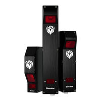
Gocator 2300 Series
LMI Technologies Gocator 2300 Series Manuals
Manuals and User Guides for LMI Technologies Gocator 2300 Series. We have
7
LMI Technologies Gocator 2300 Series manuals available for free PDF download: User Manual, Setup Manual, Quick Start Manual
LMI Technologies Gocator 2300 Series User Manual (800 pages)
Line Profile Sensors
Brand:
LMI Technologies
| Category:
Accessories
| Size: 41 MB
Table of Contents
Copyright
2
Table of Contents
3
Gocator Line Profile Sensors: User Manual
7
Introduction
13
Gocator Overview
14
Safety and Maintenance
15
Laser Safety
15
Laser Classes
16
Precautions and Responsibilities
17
Class 3B Responsibilities
17
Nominal Ocular Hazard Distance (NOHD)
18
Systems Sold or Used in the USA
19
Electrical Safety
20
Heat Warning
20
Handling, Cleaning, and Maintenance
20
Environment and Lighting
21
Getting Started
22
Hardware and Firmware Capabilities
22
Hardware Overview
23
Gocator Sensor
23
Gocator Cordsets
23
Master 100
24
Master 400 / 800 / 1200 / 2400
25
Master 810 / 2410
26
Alignment Targets
28
System Overview
29
Standalone System
29
Dual-Sensor System
30
Multi-Sensor System
31
Installation
33
Mounting
33
Orientations
34
Grounding
36
Gocator
36
Recommended Practices for Cordsets
36
Master Network Controllers
37
Additional Grounding Schemes
38
Grounding When Using a DIN Rail (Master 810/2410)
38
Installing DIN Rail Clips: Master 810 or
38
Configuring Master 810
40
Encoder Quadrature Frequency
41
Setting the Divider
41
Setting the Debounce Period
42
Rut-Scanning System Setup
42
Layout
42
Software Configuration
43
System Setup
43
System Operation
44
Network Setup
45
Client Setup
45
Gocator Setup
48
Running a Standalone Sensor System
48
Running a Dual-Sensor System
49
Next Steps
51
How Gocator Works
53
3D Acquisition
53
Clearance Distance, Field of View and Measurement Range
54
Resolution and Accuracy
55
Resolution
55
Z Linearity
56
Z Resolution
56
Profile Output
58
Coordinate Systems
58
Sensor Coordinates
58
System Coordinates
59
Part and Section Coordinates
62
Switching between Coordinate Systems
63
Resampled Data and Point Cloud Data
63
Data Generation and Processing
65
Surface Generation
65
Part Detection
65
Sectioning
66
Part Matching
66
Measurement
67
Tool Chaining
67
Anchoring Measurements
68
Geometric Features
70
Tool Data
73
Output and Digital Tracking
77
Gocator Web Interface
79
Browser Compatibility
79
Internet Explorer 11 Issues
79
Internet Explorer Switches to Software Rendering
79
Internet Explorer Displays "Out of Memory
79
User Interface Overview
80
Toolbar
82
Creating, Saving and Loading Jobs (Settings)
82
Recording, Playback, and Measurement Simulation
83
Recording Filtering
85
Downloading, Uploading, and Exporting Replay Data
87
Metrics Area
89
Data Viewer
90
Status Bar
90
Log
90
Frame Information
91
Quick Edit Mode
91
Interface Language
92
Management and Maintenance
93
Manage Page Overview
93
Sensor System
94
Dual- and Multi-Sensor Systems
94
Buddy Assignment
95
Over Temperature Protection
96
Sensor Autostart
96
Layout
96
Device Exposure Multiplexing
103
Networking
104
Motion and Alignment
105
Alignment Reference
105
Encoder Resolution
106
Encoder Value and Frequency
106
Travel Speed
106
Jobs
107
Security
108
Maintenance
109
Sensor Backups and Factory Reset
110
Firmware Upgrade
111
Support
112
Support Files
113
Manual Access
113
Software Development Kit
114
Scan Setup and Alignment
115
Scan Page Overview
115
Scan Modes
116
Triggers
117
Trigger Examples
121
Trigger Settings
122
Maximum Input Trigger Rate
124
Maximum Encoder Rate
124
Sensor
124
Active Area
124
Tracking Window
126
Transformations
128
Exposure
129
Single Exposure
130
Dynamic Exposure
131
Multiple Exposure
132
Spacing
134
Sub-Sampling
134
Spacing Interval
135
Advanced
136
Camera Gain and Dynamic Exposure
137
Material
137
Alignment
138
Alignment Types
138
Aligning Sensors
139
Encoder Calibration
145
Clearing Alignment
146
Filters
146
Gap Filling
147
Median
147
Smoothing
148
Decimation
149
Surface Generation
149
Part Detection
153
Part Detection Status
157
Edge Filtering
159
Data Viewer
160
Data Viewer Controls
160
Video Mode
163
Exposure Information
163
Exposures
163
Overexposure and Underexposure
164
Spots and Dropouts
165
Profile Mode
166
Surface Mode
168
Height Map Color Scale
171
Sections
172
Region Definition
173
Intensity Output
174
Models
176
Model Page Overview
176
Part Matching
176
Using Edge Detection
177
Creating a Model
180
Modifying a Model's Edge Points
182
Adjusting Target Sensitivity
185
Running Part Matching
186
Setting the Match Acceptance Criteria
186
Using Bounding Box and Ellipse
186
Running Part Matching
189
Using Part Matching to Accept or Reject a Part
190
Sections
190
Creating a Section
193
Deleting a Section
195
Measurement and Processing
196
Measure Page Overview
196
Data Viewer
197
Tools Panel
198
Adding and Configuring a Measurement Tool
198
Stream
199
Regions
201
Source
201
Feature Points
204
Geometric Features
206
Decisions
208
Fit Lines
208
Filters
209
Measurement Anchoring
211
Enabling and Disabling Measurements
216
Editing Tool, Input, or Output Names
217
Changing a Measurement ID
217
Duplicating a Tool
218
Removing a Tool
218
Reordering Tools
219
Profile Measurement
220
Advanced Height
220
Measurements, Data, and Settings
222
Master Comparison
223
Anchoring
224
Correction
224
Reference Line
224
Area
225
Measurements, Features, and Settings
226
Bounding Box
229
Measurements, Features, and Settings
230
Bridge Value
232
Understanding the Window and Skip Settings
232
Measurements and Settings
233
Using Window and Stddev as Metrics Measurements
235
Circle
237
Measurements, Features, and Settings
237
Closed Area
240
Measurements and Settings
240
Dimension
244
Measurements and Settings
244
Groove
247
Measurements, Features, and Settings
248
Intersect
252
Measurements, Features, and Settings
252
Line
255
Measurements, Features, and Settings
256
Panel
259
Position
263
Measurements, Features, and Settings
263
Round Corner
265
Strip
269
Script
274
Surface Measurement
276
Ball Bar
277
Bounding Box
280
Measurements, Features, and Settings
281
Countersunk Hole
285
Measurements, Features, and Settings
287
Dimension
294
Edge
298
Paths and Path Profiles
300
Measurements, Features, and Settings
301
Ellipse
312
Measurements, Features, and Settings
313
Advertisement
LMI Technologies Gocator 2300 Series User Manual (533 pages)
Profile Sensors
Brand:
LMI Technologies
| Category:
Security Sensors
| Size: 25 MB
Table of Contents
Copyright
2
Table of Contents
3
Introduction
11
Safety and Maintenance
12
Laser Safety
12
Laser Classes
13
Precautions and Responsibilities
14
Class 3B Responsibilities
14
Nominal Ocular Hazard Distance (NOHD)
15
Systems Sold or Used in the USA
16
Electrical Safety
16
Handling, Cleaning, and Maintenance
17
Environment and Lighting
17
Getting Started
19
System Overview
19
Standalone System
19
Dual-Sensor System
20
Multi-Sensor System
21
Hardware Overview
22
Gocator Sensor
22
Gocator Cordsets
22
Master
22
Master 400 / 800
23
Master 810 / 2410
25
Calibration Targets
26
Installation
28
Mounting
28
Orientations
29
Grounding: Gocator
31
Grounding: Recommended Practices for Cordsets
31
Installing DIN Rail Clips: Master 810 or
32
Grounding: Master Network Controllers
33
Grounding When Using a DIN Rail (Master 810/2410)
33
Rut-Scanning System Setup
34
Layout
34
System Setup
35
Software Configuration
36
System Operation
36
Network Setup
37
Client Setup
37
Gocator Setup
39
Running a Standalone Sensor System
39
Running a Dual-Sensor System
40
Next Steps
43
How Gocator Works
44
3D Acquisition
44
Clearance Distance, Field of View and Measurement Range
45
Resolution and Accuracy
46
Resolution
46
Z Resolution
47
Z Linearity
47
Profile Output
49
Coordinate Systems
49
Sensor Coordinates
49
System Coordinates
50
Part and Section Coordinates
52
Switching between Coordinate Systems
53
Uniform Spacing (Data Resampling)
53
Data Generation and Processing
54
Surface Generation
54
Part Detection
55
Sectioning
55
Part Matching
56
Measurement and Anchoring
56
Output and Digital Tracking
57
Gocator Web Interface
58
User Interface Overview
58
Toolbar
59
Creating, Saving and Loading Jobs (Settings)
59
Recording, Playback, and Measurement Simulation
61
Recording Filtering
63
Downloading, Uploading, and Exporting Replay Data
64
Metrics Area
66
Data Viewer
67
Status Bar
67
Log
67
Frame Information
68
Interface Language
68
System Management and Maintenance
70
Manage Page Overview
70
Sensor System
71
Sensor Autostart
71
System Layout
71
Buddy Assignment
73
Exposure Multiplexing
74
Over Temperature Protection
74
Networking
75
Motion and Alignment
75
Alignment Reference
76
Encoder Resolution
76
Encoder Value and Frequency
77
Travel Speed
77
Jobs
77
Security
79
Maintenance
80
Sensor Backups and Factory Reset
81
Firmware Upgrade
82
Support
83
Support Files
84
Manual Access
84
Software Development Kit
85
Scan Setup and Alignment
86
Scan Page Overview
86
Scan Modes
87
Triggers
88
Trigger Examples
91
Trigger Settings
92
Maximum Input Trigger Rate
93
Maximum Encoder Rate
94
Sensor
94
Active Area
94
Tracking Window
95
Transformations
97
Exposure
98
Single Exposure
99
Dynamic Exposure
100
Multiple Exposure
101
Spacing
102
Sub-Sampling
102
Spacing Interval
103
Material
104
Alignment
106
Alignment States
106
Alignment Types
106
Alignment: with and Without Encoder Calibration
106
Aligning Sensors
107
Clearing Alignment
110
Filters
110
Gap Filling
110
Median
111
Smoothing
112
Decimation
113
Surface Generation
113
Part Detection
117
Edge Filtering
120
Data Viewer
121
Data Viewer Controls
122
Video Mode
122
Exposure Information
122
Exposures
122
Overexposure and Underexposure
123
Spots and Dropouts
124
Profile Mode
125
Section Mode
127
Surface Mode
128
Height Map Color Scale
131
Region Definition
132
Intensity Output
133
Models
134
Model Page Overview
134
Part Matching
135
Using Edge Detection
136
Creating a Model
139
Modifying a Model's Edge Points
141
Adjusting Target Sensitivity
144
Setting the Match Acceptance Criteria
145
Running Part Matching
145
Using Bounding Box and Ellipse
145
Configuring a Bounding Box or an Ellipse147
147
Running Part Matching
148
Using Part Matching to Accept or Reject a Part
149
Sections
149
Creating a Section
152
Deleting a Section
154
Measurement
155
Measure Page Overview
155
Data Viewer
156
Tools Panel
156
Adding and Configuring a Tool
156
Source
157
Streams (Sections)
158
Regions
158
Decisions
159
Filters
161
Measurement Anchoring
162
Enabling and Disabling Measurements
163
Editing a Tool or Measurement Name
165
LMI Technologies Gocator 2300 Series User Manual (523 pages)
Profile Sensors
Brand:
LMI Technologies
| Category:
Accessories
| Size: 24 MB
Table of Contents
Copyright
2
Table of Contents
3
Introduction
11
Safety and Maintenance
12
Laser Safety
12
Laser Classes
13
Precautions and Responsibilities
14
Class 3B Responsibilities
14
Nominal Ocular Hazard Distance (NOHD)
15
Systems Sold or Used in the USA
16
Electrical Safety
16
Handling, Cleaning, and Maintenance
17
Environment and Lighting
17
Getting Started
19
System Overview
19
Standalone System
19
Dual-Sensor System
20
Multi-Sensor System
21
Hardware Overview
22
Gocator Sensor
22
Gocator Cordsets
22
Master 1200/2400
24
Calibration Targets
25
Installation
27
Grounding - Gocator
27
Recommended Grounding Practices - Cordsets
27
Grounding - Master
28
Mounting
28
Orientations
29
Rut-Scanning System Setup
31
Layout
31
System Setup
32
Software Configuration
32
System Operation
33
Network Setup
34
Client Setup
34
Gocator Setup
36
Running a Standalone Sensor System
36
Running a Dual-Sensor System
37
Next Steps
39
How Gocator Works
41
3D Acquisition
41
Clearance Distance, Field of View and Measurement Range
42
Resolution and Accuracy
43
Resolution
43
Z Resolution
44
Z Linearity
44
Profile Output
46
Coordinate Systems
46
Sensor Coordinates
46
System Coordinates
47
Part and Section Coordinates
49
Switching between Coordinate Systems
50
Uniform Spacing (Data Resampling)
50
Data Generation and Processing
51
Surface Generation
51
Part Detection
52
Sectioning
52
Part Matching
53
Measurement and Anchoring
53
Output and Digital Tracking
54
Gocator Web Interface
55
User Interface Overview
55
Toolbar
56
Creating, Saving and Loading Jobs (Settings)
56
Recording, Playback, and Measurement Simulation
58
Recording Filtering
60
Downloading, Uploading, and Exporting Replay Data
61
Metrics Area
63
Data Viewer
64
Status Bar
64
Log
64
Frame Information
65
Interface Language
65
System Management and Maintenance
67
Manage Page Overview
67
Sensor System
68
Sensor Autostart
68
System Layout
68
Buddy Assignment
70
Exposure Multiplexing
71
Over Temperature Protection
71
Networking
72
Motion and Alignment
72
Alignment Reference
73
Encoder Resolution
73
Encoder Value and Frequency
74
Travel Speed
74
Jobs
74
Security
76
Maintenance
77
Sensor Backups and Factory Reset
78
Firmware Upgrade
79
Support
79
Support Files
80
Manual Access
81
Software Development Kit
81
Scan Setup and Alignment
82
Scan Page Overview
82
Scan Modes
83
Triggers
84
Trigger Examples
86
Trigger Settings
87
Sensor
89
Active Area
89
Tracking Window
90
Transformations
92
Exposure
93
Single Exposure
94
Dynamic Exposure
95
Multiple Exposure
96
Spacing
97
Sub-Sampling
97
Spacing Interval
98
Material
99
Master
100
Alignment
101
Alignment States
101
Alignment Types
101
Alignment: with and Without Encoder Calibration
101
Aligning Sensors
102
Clearing Alignment
105
Filters
105
Gap Filling
105
Median
106
Smoothing
107
Decimation
108
Surface Generation
108
Part Detection
112
Edge Filtering
115
Data Viewer
116
Data Viewer Controls
117
Video Mode
117
Exposure Information
117
Exposures
117
Overexposure and Underexposure
118
Spots and Dropouts
119
Profile Mode
120
Section Mode
122
Surface Mode
123
Height Map Color Scale
126
Region Definition
127
Intensity Output
128
Models
129
Model Page Overview
129
Part Matching
130
Using Edge Detection
131
Creating a Model
134
Modifying a Model's Edge Points
136
Adjusting Target Sensitivity
139
Setting the Match Acceptance Criteria
140
Running Part Matching
140
Using Bounding Box and Ellipse
140
Configuring a Bounding Box or an Ellipse142
142
Running Part Matching
143
Using Part Matching to Accept or Reject a Part
144
Sections
144
Creating a Section
147
Deleting a Section
149
Measurement
150
Measure Page Overview
150
Data Viewer
151
Tools Panel
151
Adding and Configuring a Tool
151
Source
152
Streams (Sections)
153
Regions
153
Decisions
154
Filters
156
Measurement Anchoring
157
Enabling and Disabling Measurements
158
Editing a Tool or Measurement Name
160
Changing a Measurement ID
160
Removing a Tool
161
Profile Measurement
161
Advertisement
LMI Technologies Gocator 2300 Series User Manual (431 pages)
Line Profile 3D Smart Sensors/Laser Profilers
Brand:
LMI Technologies
| Category:
Accessories
| Size: 22 MB
Table of Contents
Copyright
2
Table of Contents
3
Introduction
10
Safety and Maintenance
11
Laser Safety
11
Laser Classes
12
Precautions and Responsibilities
12
Class 3B Responsibilities
13
Nominal Ocular Hazard Distance (NOHD)
14
Systems Sold or Used in the USA
15
Electrical Safety
15
Environment and Lighting
16
Sensor Maintenance
17
Getting Started
18
System Overview
18
Standalone System
18
Dual-Sensor System
18
Multi-Sensor System
19
Hardware Overview
21
Gocator 2300 & 2880 Sensor
21
Gocator 2300 & 2880 Cordsets
21
Master 100
22
Master 1200/2400
23
Master 400/800
23
Calibration Targets
24
Installation
26
Grounding - Gocator
26
Recommended Grounding Practices - Cordsets
26
Grounding - Master 400/800/1200/2400
27
Mounting
27
Orientations
28
Rut-Scanning System Setup
31
Layout
31
System Setup
31
Software Configuration
32
System Operation
33
Network Setup
34
Client Setup
34
Gocator Setup
36
Running a Standalone Sensor System
36
Running a Dual-Sensor System
37
Next Steps
40
Theory of Operation
42
3D Acquisition
42
Principle of 3D Acquisition
42
Resolution and Accuracy
43
Resolution
43
Z Resolution
43
Z Linearity
44
Profile Output
45
Coordinate Systems
45
Sensor Coordinates
45
System Coordinates
45
Uniform Spacing (Data Resampling)
46
Gocator Web Interface
47
User Interface Overview
47
Toolbar
48
Creating, Saving and Loading Jobs (Settings)
48
Recording, Playback, and Measurement Simulation
50
Downloading, Uploading, and Exporting Replay Data
52
Log
54
Metrics Area
54
Data Viewer
55
System Management and Maintenance
56
Manage Page Overview
56
Sensor System
57
Sensor Autostart
57
Dual-Sensor System Layout
58
Buddy Assignment
59
Exposure Multiplexing
60
Over Temperature Protection
61
Networking
61
Motion and Alignment
62
Alignment Reference
63
Encoder Resolution
63
Encoder Value and Frequency
64
Travel Speed
64
Jobs
64
Security
66
Maintenance
67
Sensor Backups and Factory Reset
68
Firmware Upgrade
69
Support
70
Support Files
71
Manual Access
71
Software Development Kit
72
Scan Setup and Alignment
73
Scan Page Overview
73
Scan Modes
74
Triggers
75
Trigger Examples
77
Trigger Settings
78
Sensor
80
Active Area
80
Tracking Window
82
Transformations
83
Exposure
84
Single Exposure
85
Dynamic Exposure
86
Multiple Exposure
87
Spacing
88
Sub-Sampling
88
Spacing Interval
89
Material
90
Alignment
92
Alignment States
92
Alignment Types
93
Alignment: with and Without Encoder Calibration
93
Aligning Sensors
94
Clearing Alignment
96
Filters
97
Gap Filling
97
Median
98
Smoothing
99
Master
100
Decimation
100
Surface Generation
100
Part Detection
103
Edge Filtering
106
Data Viewer
107
Data Viewer Controls
108
Video Mode
108
Exposure View
108
Spots and Dropouts
110
Profile Mode
111
Surface Mode
113
Height Map Color Scale
115
Region Definition
116
Intensity Output
117
Models and Part Matching
118
Model Page Overview
118
Part Matching
119
Using Edge Detection
120
Creating a Model
123
Modifying a Model's Edge Points
125
Adjusting Target Sensitivity
128
Running Part Matching
129
Setting the Match Acceptance Criteria
129
Using Bounding Box and Ellipse
129
Configuring a Bounding Box or an Ellipse131
131
Running Part Matching
132
Using Part Matching to Accept or Reject a Part
132
LMI Technologies Gocator 2300 Series User Manual (369 pages)
Gocator 2000/2300 Series
Brand:
LMI Technologies
| Category:
Accessories
| Size: 26 MB
Table of Contents
Table of Contents
4
Introduction
3
Safety and Maintenance
9
Laser Safety
9
Laser Classes
10
Class 3B Responsibilities
11
Precautions and Responsibilities
11
Systems Sold or Used in the USA
12
Electrical Safety
13
Environment and Lighting
14
Sensor Maintenance
14
Getting Started
16
System Overview
16
Standalone System
16
Dual Sensor System
18
Multi-Sensor System
20
Hardware
21
Gocator 2000 Sensor
21
Gocator 2300 Sensor
22
Master 100
23
Master 200
24
Master 400/800
25
Master 1200/2400
26
Gocator 2000 Cordsets
27
Gocator 2300 Cordsets
27
Calibration Targets
28
Installation
29
Grounding - Gocator
29
Grounding - Master 400/800/1200/2400
29
Mounting
30
Orientations
31
Software
33
User Interface Overview
33
Connecting to a New Sensor
34
Running for the First Time
36
Running a Standalone Sensor System
36
Running a Dual Sensor System
38
Next Steps
42
Setup and Calibration
43
Setup Page
43
Operation Modes
45
Data Viewer
46
Video Mode
46
Profile and Raw Mode
47
Whole Part
48
Data Viewer Controls
50
Region Definition
50
Height Map Color Scale
51
Profile Output
52
Coordinate Systems
52
Resampled and Raw Profile Format
53
Intensity Output
54
Trigger
55
Examples
57
Settings
59
Active Area
60
Tracking Window
61
Exposure
63
Single Exposure
64
Dynamic Exposure
65
Multiple Exposures
66
Resolutions
67
Resolution
67
Z Resolution
68
Transformations
69
Dual Sensor System Layout
70
Overlap
71
Reverse
71
Calibration
72
Alignment Vs. Travel Calibration
72
Calibration States
72
Alignment Calibration
73
Travel Calibration
74
Clearing Calibration
75
Filters
76
Resampling Interval
77
Gap Filling
78
Smoothing
79
Part Detection
80
Measurement
82
Measurement Page
82
Adding and Removing Measurements
83
Changing the Measurement Name
84
Profile Sources
86
Decisions
87
Output Filters
88
Profile Fixturing
89
Script Measurement
91
Built-In Functions
91
Profile Measurement Tools
95
Master
100
Feature Points
102
Fit Lines
104
Measurement Types
105
Width
105
Height
106
Distance
107
Position X
108
Position Z
109
Center X
110
Center Z
111
Angle X
112
Intersect X
113
Intersect Z
114
Intersect Angle
115
Intersect Area
116
Box Area
117
Difference Area
118
Difference Peak
119
Circle Radius
120
Circle X
121
Circle Z
122
Line Standard Deviation
123
Line Error Min
124
Line Error Max
125
Line Percentile
126
Gap
127
LMI Technologies Gocator 2300 Series Setup Manual (13 pages)
4.x Dual-Sensor
Brand:
LMI Technologies
| Category:
Security Sensors
| Size: 1 MB
Table of Contents
Table of Contents
1
Overview
2
Software and Hardware Requirements
2
Dual-Sensor Setup Steps
2
Connecting the Components
2
System Layouts
3
Running a Dual-Sensor System
3
Alignment and Measurement Example
7
Dual-Sensor Mounting Layouts and Orientations
12
LMI Technologies Gocator 2300 Series Quick Start Manual (2 pages)
Brand:
LMI Technologies
| Category:
Security Sensors
| Size: 1 MB
Advertisement
Related Products
LMI Technologies Gocator 2330
LMI Technologies 2340
LMI Technologies Gocator 2350
LMI Technologies Gocator 2370
LMI Technologies Gocator 2380
LMI Technologies Gocator 2320
LMI Technologies Gocator 2375
LMI Technologies Gocator 2342
LMI Technologies 2070
LMI Technologies 2080
LMI Technologies Categories
Accessories
Scanner
Security Sensors
Video Card
Laser Level
More LMI Technologies Manuals
Login
Sign In
OR
Sign in with Facebook
Sign in with Google
Upload manual
Upload from disk
Upload from URL