Sign In
Upload
Manuals
Brands
Littelfuse Manuals
Relays
PGR-8800
Littelfuse PGR-8800 Manuals
Manuals and User Guides for Littelfuse PGR-8800. We have
2
Littelfuse PGR-8800 manuals available for free PDF download: Manual, User Manual
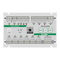
Littelfuse PGR-8800 Manual (98 pages)
Arc-Flash Relay
Brand:
Littelfuse
| Category:
Relays
| Size: 5.04 MB
Table of Contents
Table of Contents
3
Introduction
7
Current-Supervised Arc-Flash Protection
7
Definite-Time Overcurrent Protection
7
Fail-Safe Operation
7
Fast-Fault Location
7
USB Interface
8
Scalable System
8
Upstream Circuit Breaker Tripping
8
Installation
9
PGR-8800 Outline and Mounting Details
9
PGR-8800 Typical Wiring Diagram
10
PGR-8800 24-VDC Source Typical Wiring Diagram
11
Power Supply
12
AC Supply
12
DC Supply
12
Low-Voltage DC Supply
13
External 24-V Battery Backup
13
Optical Sensors
14
Local Sensor Detection Zone for a 3 Ka Fault
14
PGA-LS10 Photoelectric Point Sensor with Sensor Check
15
PGA-LS10 Detection Range for a 3 Ka Fault
15
PGA-LS10 Connection
16
PGA-LS10 Connection Diagram
16
PGA-LS10 Installation
17
PGA-LS10 Mounting Detail
17
PGA-LS20 and PGA-LS30 Fiber-Optic Sensor with Sensor Check
18
Fiber Connection
18
Receiver Wiring Connections
18
Transmitter Wiring Connections
18
PGA-LS20 and PGA-LS30 Connection
19
PGA-LS20 and PGA-LS30 Connection Diagram
19
Sensor Placement
20
General Guidelines
20
Switchgear Protection
20
Transformer Protection
20
Current Sensors
21
Current Inhibit Mode
21
Overcurrent Protection
21
Current Sensor Characteristics
22
Digital Inputs
23
Inhibit
23
Trip
23
Reset
23
Circuit Check
23
Outputs
24
Online
24
Service
25
Tripped
25
LED Flash Patterns
28
Trip Coil
29
Pgr-8800 Buttons
31
Mode
31
Trip
31
Reset
31
Mode + Reset
31
Mode + Trip
31
Link
32
Configuration
32
Button Function
32
Modbus Communication
33
Usb Interface
34
Connecting to a PC
34
Configuration Software
35
Configuration Software Tabs
35
Configuration Software Buttons
36
Default Configuration
36
General Settings
37
Optical-Sensor Settings
37
Current-Sensor Settings
39
Output Settings
42
Online Output
42
Service Output
43
Tripped Output
45
Trip Coil Output
47
Communications Settings
50
Advanced Settings
53
About Tab
54
Data Log Drive
54
Firmware Upgrade
56
Commissioning
57
Configuration of Installed Sensors
57
Testing the Sensors
57
Testing the Trip Coil
58
Full Operation Test (Online)
58
Light Sensitivity Adjustment
59
Fiber-Optic Sensor Adjustment
59
Sensor Adjustment for a Fiber Length Other than 60 CM (24")
59
Sensor Adjustment in Small Compartments
60
Specifications
61
Pgr-8800
61
Sensors
65
Ordering Information
66
Warranty
66
Appendix A Pgr-8800 Modbus Rtu Protocol
67
Protocol
67
Configuration Setup
67
Message Synchronization
67
Error Checking
67
Function Codes Supported
68
Read Input/Holding Registers (Code 04/03)
68
Write to Register
68
Write Single Register (Code 6)
68
Write Multiple Registers (Code 16)
69
Exception Responses
69
PGR-8800 Database
69
Specifications
69
Appendix B Modbus Communications Database Table
70
Appendix C Coordinated Tripping of Upstream Breakers
76
System Overview
76
Circuit Breaker Feedback Detection
76
Current Sensor Detection
76
Total Clearing Time
76
Arc Detection Delay
76
Circuit Breaker Operating Time
77
Output Delay
77
Total Clearing Time Examples
77
Relay Output
77
Link Output
77
Circuit Breaker Operating Times
77
PGA-1100 Diode Logic Unit
78
Application and Configuration
78
Single PGR-8800 Configuration
78
Dual PGR-8800 Configuration Using Link Interface
82
Single PGR-8800 Configuration with Current Sensor Input
83
Single PGR-8800 Configuration with Current Sensor Input
84
Dual PGR-8800 Configuration Using Link Interface and Current Sensor Input
87
Configuration of Multiple Inputs and Outputs
90
Tripping Common Upstream Circuit Breaker from Several Zones Using
91
Tripping Common Upstream Circuit Breaker from Several Zones
91
Appendix D System Parameters and Setup Record
92
Advertisement
Littelfuse PGR-8800 User Manual (82 pages)
Arc-Flash Relay
Brand:
Littelfuse
| Category:
Relays
| Size: 4.59 MB
Table of Contents
PGR-8800 Arc-Flash Relay Rev
2
Table of Contents
3
Introduction
7
Current-Supervised Arc-Flash Protection
7
Definite-Time Overcurrent Protection
7
Fail-Safe Operation
7
Fast Fault Location
7
USB Interface
8
Scalable System
8
Upstream Circuit Breaker Tripping
8
PGR-8800 Outline and Mounting Details
9
Installation
9
PGR-8800 Typical Wiring Diagram
10
PGR-8800 24-VDC Source Wiring Diagram
11
Power Supply
12
AC Supply
12
DC Supply
12
Low-Voltage DC Supply
13
External 24-V Battery Backup
13
Local Sensor Detection Zone for a 3 Ka Fault
14
Optical Sensors
14
PGA-LS10 Detection Range for a 3 Ka Fault
15
PGA-LS10 Connection
16
PGA-LS10 Photoelectric Point Sensor with Sensor Check
15
PGA-LS10 Connection Diagram
16
PGA-LS10 Installation
17
PGA-LS10 Mounting Details
17
PGA-LS20 and PGA-LS25 Fiber-Optic Sensor with Sensor Check
18
Fiber Connection
18
Receiver Wiring Connections
18
Transmitter Wiring Connections
18
PGA-LS20 and PGA-LS25 Connection
19
PGA-LS20 and PGA-LS25 Connection Diagram
19
Fiber-Optic Sensor Adjustment
20
Sensor Adjustment for a Fiber Length Other than 60 CM
20
Sensor Adjustment in Small Compartments
20
Sensor Placement
21
General Guidelines
21
Switchgear Protection
21
Transformer Protection
21
Current Sensors
22
Current Inhibit Mode
22
Overcurrent Protection
22
Current Sensor Characteristics
23
Digital Inputs
24
Inhibit
24
Trip
24
Reset
24
Circuit Check
24
Service
25
Tripped
25
Outputs
25
Online
25
Trip Coil
26
Led Indication
27
LED Flash Patterns
27
Pgr-8800 Buttons
30
Mode
30
Trip
30
Reset
30
Mode + Reset
30
Mode + Trip
30
Link
31
Configuration
31
Button Function
31
Modbus Communication
32
USB Interface
33
Connecting to a PC
33
Configuration Software
34
Configuration Software Tabs
34
Configuration Software Buttons
35
Default Configuration
35
General Settings
36
Optical-Sensor Settings
36
Current-Sensor Settings
38
Digital-Input Settings
40
Output Settings
41
Trip Coil Output
41
Coordinated Tripping
42
Communications Settings
43
Advanced Settings
46
About Tab
47
Data Log Drive
47
Commissioning
48
Configuration of Installed Sensors
48
Testing the Sensors
48
Testing the Trip Coil
49
Full Operation Test (Online)
49
Light Sensitivity Adjustment
49
Specifications
50
Ordering Information
53
Warranty
54
Message Synchronization
55
Error Checking
55
Appendix A PGR-8800 MODBUS RTU Protocol
55
Protocol
55
Configuration Setup
55
Function Codes Supported
56
Read Input/Holding Registers (Code 04/03)
56
Write to Register
56
Write Single Register (Code 6)
56
Write Multiple Registers (Code 16)
57
Exception Responses
57
PGR-8800 Database
57
Specifications
57
Appendix B Modbus Communications Database Table
58
Appendix C Coordinated Tripping of Upstream Breakers
64
System Overview
64
Circuit Breaker Feedback Detection
64
Current Sensor Detection
64
Total Clearing Time
64
Arc Detection Delay
64
Circuit Breaker Operating Time
64
Output Delay
65
Total Clearing Time Examples
65
Relay Output
65
Link Output
65
D1100 Diode Logic Unit
65
Application and Configuration
66
Single PGR-8800 Configuration
66
Dual PGR-8800 Configuration Using Link Interface
70
Single PGR-8800 Configuration with Current Sensor Input
71
Single PGR-8800 Configuration with Current Sensor Input
72
Dual PGR-8800 Configuration Using Link Interface and Current Sensor Input
74
Configuration of Multiple Inputs and Outputs
76
Tripping Common Upstream Circuit Breaker from Several Zones Using D1100
77
Appendix D System Parameters and Setup Record
78
Advertisement
Related Products
Littelfuse POWR-GARD PGR-4704
Littelfuse PGR-6100
Littelfuse PGR-6101
Littelfuse PGR-3200
Littelfuse PGR-3100
Littelfuse POWR-GARD PGR-3200-120
Littelfuse 111-Insider-P
Littelfuse 231-Insider-P
Littelfuse AF0100
Littelfuse D0920
Littelfuse Categories
Relays
Monitor
Switch
Microphone
Power distribution unit
More Littelfuse Manuals
Login
Sign In
OR
Sign in with Facebook
Sign in with Google
Upload manual
Upload from disk
Upload from URL