Sign In
Upload
Manuals
Brands
LiteOn Manuals
Servo Drives
ISA-7-020-S1
LiteOn ISA-7-020-S1 Manuals
Manuals and User Guides for LiteOn ISA-7-020-S1. We have
1
LiteOn ISA-7-020-S1 manual available for free PDF download: User Manual
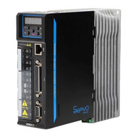
LiteOn ISA-7-020-S1 User Manual (237 pages)
Standard General Purpose Servo Drive
Brand:
LiteOn
| Category:
Servo Drives
| Size: 9 MB
Table of Contents
Table of Contents
3
Chapter 1 Panel and Operation
11
Product Check
11
Comparison of the Product Numbers
12
Description for the Name Plate
12
Description for the Model Number
13
Name of each Part in the Servo Drive
14
Operating Mode
15
Chapter 2 Steps for Commissioning and Tuning
16
Notes
16
Condition of the Storage Environment
16
Condition of Installation Environment
16
Direction of and Space for Installation
17
Recommended Specifications for the Circuit Breaker and Fuse
20
EMI Filter Selection
20
Selection for the Regenerative Resistor
23
Chapter 3 Wiring
24
Connection for the Peripheral Device and Main Power Circuit
24
Wiring Diagram of the Peripheral Device
24
Connector and Terminal of the Drive
26
Power Wiring
27
Specifications for the U, V, W Connectors of the Motor
28
Specifications Regarding the Connector for the Leadwire of the Encoder
29
Filament Selection
31
Basic Block Diagram of the Server System
32
Models with the Power Equal to or below 200W (no Built-In Regenerative Resistor or Fan)
32
750W Model (with Regeneration Resistor but no Fan)
33
1Kw ~ 2Kw Model (with Regeneration Resistor and Fan)
34
CN1 I/O Signal Wiring
35
CN1 I/O Layout of the Connector Terminal
35
CN1 I/O Connector Signal
37
Interface Wiring Diagram (CN1)
42
User-Specified DI and DO Signals
51
CN2 Wiring of the the Encoder Signal
52
CN3 Wiring for the Signal of the Communication Connector
54
CN5 Analog Voltage Output Terminal
55
Standard Wiring
57
Standard Wiring for the Position Mode
57
Standard Wiring for the Speed Mode
58
Standard Wiring for the Torque Mode
59
Chapter 4 Panel and Operation
60
Panel Display and Key Description
60
Panel Operating Process
61
Status Display
63
Description for the Display of Status Value
63
Display of Storage Setting
63
Display of Decimal Point
64
Display of the Warning Message
64
Monitoring Display
64
Operation of the General Function
65
Operation for Displaying the Record of the Abnormal Status
65
Operation for the Jog Mode
65
Enforced Operation of the Digital Output
67
Operation for the Diagnosis of Digital Input
67
Operation for the Diagnosis of Digital Output
69
Chapter 5 Steps for Commissioning and Tuning
70
No-Load Detection
70
Power Transmission for the Drive
71
No-Load Jog Test
74
No-Load Speed Test
75
Tuning Steps
76
Process of the Tuning Steps
76
Flowchart of the Tuning Steps in the Semi-Auto Gain Mode
76
Flowchart of the Tuning Steps in the Automatic Gain Mode
78
Manual Adjustment of Gain Parameters
80
Relationship of the Gain Adjustment Mode with the Parameters
81
Solutions for Mechanical Resonance
82
Chapter 6 Parameters and Functions
83
Definitions of Parameters
83
Parameters Overview
84
Parameter List
84
Classification of the Parameter Function
90
Parameters for the Monitoring and the General Output Setting
90
Parameters Related to the Filter Smoothness and Resonance Suppression
91
Parameters Related to Gain and Switch
92
Parameters Related to the Position Control
93
Parameters Related to the Speed Control
94
Parameters Related to the Torque Control
95
Parameters for the Planning of the Digital I/O Pin and for the Setting Related to the Output
96
Communication Parameters
98
Diagnostic Parameters
99
Parameter Description
100
Chapter 7 Control Function
156
Selection of Operating Mode
156
Position Mode
157
Command of Position Mode
157
Control Structure of the Position Mode
158
Electronic Gear Ratio
159
Adjustment for the Gain of Position Circuit
160
Speed Mode
162
Selection of Speed Command
162
Control Structure of the Speed Mode
163
Smoothing of Speed Command
164
Proportioner at the Analog Command End
166
Timing Diagram of Speed Mode
168
Adjustment for the Gain of Speed Circuit
169
Resonance Suppression Unit
175
Torque Mode
182
Selection of Torque Command
182
Control Structure of the Torque Mode
183
Smoothing of Torque Command
184
Proportioner at the Analog Command End
184
Timing Diagram of Torque Mode
185
Mixed Mode
186
Position/Speed Mixed Mode
186
Position/Torque Mixed Mode
186
Speed/Torque Mixed Mode
186
Others
187
Use of the Speed Limit
187
Use of the Torque Limit
187
Analog Monitoring
188
Use of the Electromagnetic Brake
189
Use of the Electromagnetic Brake
190
Chapter 8 Communication Mechanism
192
RS-485/RS-232 Communication Hardware Interface
192
Advertisement
Advertisement
Related Products
LiteOn ISA-7 Series
LiteOn ISA-7-040-S1
LiteOn ISA-7-075-S1
LiteOn ISA-7-100-S1
LiteOn ISA-7-150-S2
LiteOn ISA-7-200-S2
LiteOn Categories
Control Unit
DVD Recorder
Keyboard
Wireless modules
Power Supply
More LiteOn Manuals
Login
Sign In
OR
Sign in with Facebook
Sign in with Google
Upload manual
Upload from disk
Upload from URL