
Summary of Contents for LiteOn ISA-7 Series
- Page 1 Lite-On Technology Corp. Industrial Automation User Manual ISA-7 Servo Drive series Standard General Purpose Servo Drive Technical Manual...
- Page 2 Lite-On Technology Corp. Industrial Automation Revision History...
-
Page 3: Table Of Contents
Lite-On Technology Corp. Industrial Automation Contents CHAPTER 1 PANEL AND OPERATION ..............11 Product check ..............................11 1.1. Comparison of the product numbers ......................12 1.2. Description for the name plate ..........................12 1.2.1. Description for the model number ........................13 1.2.2. - Page 4 Lite-On Technology Corp. Industrial Automation CN5 Analog voltage output terminal ......................55 3.6. Standard wiring ............................... 57 3.7. Standard wiring for the position mode ........................ 57 3.7.1. Standard wiring for the speed mode ........................58 3.7.2. Standard wiring for the torque mode ........................59 3.7.3.
- Page 5 Lite-On Technology Corp. Industrial Automation Parameters related to gain and switch .......................... 92 Parameters related to the position control ........................93 Parameters related to the speed control ........................94 Parameters related to the torque control ........................95 Parameters for the planning of the digital I/O pin and for the setting related to the output ........96 Communication parameters ............................
- Page 6 Lite-On Technology Corp. Industrial Automation RS-485/RS-232 Communication parameter setting ..................193 8.2. MODBUS protocol ............................195 8.3. CHAPTER 9 WARNING TROUBLESHOOTING ..........200 Drive Alarm List ............................200 9.1. Reason for and handling of the alarm ......................202 9.2. Alarm troubleshooting ..........................206 9.3.
- Page 7 Lite-On Technology Corp. Industrial Automation 11.6. Digital output definition(absolute encoder function) ................ 234 11.7. Absolute System Alarm List ........................234 11.7.1. Reason for and handling of the alarm ...................... 235 11.8. Display of status value ..........................237...
- Page 8 Lite-On Technology Corp. Industrial Automation PREFACE Thank you for using our product. The manual provides the information for the use of the ISA-7 servo drive and motor. The manual is provided as a reference for the following users: Designer of the system integration for the machine ...
- Page 9 Industrial Automation Safety precautions The ISA-7 series is an open type servo drive that must be installed in a shielded control box for operation. The drive uses precise feedback control and combines a digital signal processor (DSP) with high-performance computing. It controls the IGBT to generate current output to drive the three-phase permanent-magnet synchronous motor (PMSM) to achieve precise positioning.
- Page 10 Lite-On Technology Corp. Industrial Automation Maintenance and inspection Do not touch the interior of the servo drive and motor, otherwise it may cause electric shock. Do not remove the drive panel when the power is on, otherwise it may result in electric shock.
-
Page 11: Chapter 1 Panel And Operation
Lite-On Technology Corp. Industrial Automation Chapter 1 Panel and Operation 1.1. Product check Damages may be caused by negligence and during delivery when the product is purchased. Check the following items. Contact the factory or agent for the following. Inspection item Contents Accuracy of the product Check if the model number of the motor and drive is the same as the one... -
Page 12: Comparison Of The Product Numbers
Lite-On Technology Corp. Industrial Automation 1.2. Comparison of the product numbers 1.2.1. Description for the name plate ISA-7 series servo drive Description for the name plate Product number Power specifications Input power specifications Output power specifications The firmware version... -
Page 13: Description For The Model Number
Lite-On Technology Corp. Industrial Automation 1.2.2. Description for the model number Input power Version S: Standard version Rated power Series 7:7 series Product type Management number Encoder N: Incremental/17bit A: Absolute/17bit Axle end specifications/oil seal S: Straight shaft/without oil seal Model of the electric machinery: K: key shaft/without oil seal Output/rotor inertia... -
Page 14: Name Of Each Part In The Servo Drive
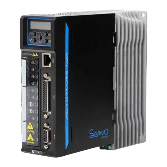
Lite-On Technology Corp. Industrial Automation 1.3. Name of each part in the servo drive Seven-segment display: It has five digits and shows the drive status or alarm. Operating button: It can be used to switch the parameter/function and execute the monitoring setting. -
Page 15: Operating Mode
Lite-On Technology Corp. Industrial Automation 1.4. Operating mode This drive provides numerous operating modes for the user. These modes are shown as follow: Mode name Mode code Description Position mode The drive receives the position command and controls the motor to move to the target position. (Terminal input) The position command is input from the terminal block. -
Page 16: Chapter 2 Steps For Commissioning And Tuning
2.3. Condition of installation environment Operating temperature: ISA-7 series servo drive: 0°C ~ 55°C (32°F ~ 131°F) ISA-7 series servo motor: 0°C ~ 40°C (32°F ~ 104°F) The product must be placed in a well ventilated area if the ambient temperature exceeds 45°C. If the product is placed in the distribution box, the size and ventilation of the distribution box must be able to prevent the electronic device in the distribution box from overheating. -
Page 17: Direction Of And Space For Installation
Drive installation: The ISA-7 series server drive must be installed vertically on a dry and stable platform complying to the NEMA standard. To ensure the circulation of ventilation air and heat radiation remain effective, it is required to keep a sufficient space between the upper, lower, left and right sides of the servo drive and the object and guard plate (wall) nearby for the installation of the AC servo drive. - Page 18 Lite-On Technology Corp. Industrial Automation Motor installation: The ECMA series servo motor must be installed properly on a dry and stable platform. Ensure the circulation of the ventilation air and heat radiation remain effective for installation and keep the earth adequate.
- Page 19 Lite-On Technology Corp. Industrial Automation...
-
Page 20: Recommended Specifications For The Circuit Breaker And Fuse
Lite-On Technology Corp. Industrial Automation 2.5. Recommended specifications for the circuit breaker and fuse Strongly recommended: CSA / UL certified fuse and circuit breaker Drive model Circuit breaker Fuse Operating Mode Normal Normal ISA-7-020-S1 ISA-7-040-S1 ISA-7-075-S1 ISA-7-100-S1 ISA-7-150-S2 ISA-7-200-S2 2.6. EMI filter selection Notes for the installation of the EMI filter All electronic equipment (including the servo drive) generates certain high or low frequency noises during normal operation. - Page 21 Lite-On Technology Corp. Industrial Automation Surge Protector Model Rated Voltage DC Breakdown Current Life Marker 8/20μs-1,000A RSPD-250-U4 250Vac 700+-25% Approx. OKAYA 300times EMC Filter Item Power Servo Drive EMI Filter model number Marker 200W ISA-7-020-S1 B84113C0000x110 B84143A0008R105 EPCOS 400W ISA-7-040-S1 B84113C0000x110 B84143A0008R105 EPCOS...
- Page 22 Lite-On Technology Corp. Industrial Automation 1000W ISA-7-100-S1 FN 351 H-16-29 Schaffner 1500W ISA-7-150-S2 FN 351 H-16-29 Schaffner 2000W ISA-7-200-S2 FN 351 H-36-33 Schaffner Clamp filter <24V Power cable, Motor cable, Encoder cable, Interface cable> Manufacture’s Part No. Manufacturer ZCAT3035-1330 39 +- 1 34 +- 1 13 +- 1 30 +- 1...
-
Page 23: Selection For The Regenerative Resistor
The energy recharged can only be consumed by the regenerative resistor when the voltage rises to a certain value. The regenerative resistor is included in the drive and available for external connection. The table below lists the specifications of the regenerative resistor offered by the ISA-7 series. Drive Specifications of the built-in... -
Page 24: Chapter 3 Wiring
Lite-On Technology Corp. Industrial Automation Chapter 3 Wiring The chapter explains the connecting method of the servo drive and the meaning of all signals. It also lists the illustration of the standard wiring in various modes. 3.1. Connection for the peripheral device and main power circuit 3.1.1. - Page 25 Lite-On Technology Corp. Industrial Automation Installation notes: Make sure that the power supply and wiring for the R S T and L1 and L2 must be accurate. Make sure that the phase sequence regarding the wiring for the servo motor output U V W is correct.
-
Page 26: Connector And Terminal Of The Drive
Lite-On Technology Corp. Industrial Automation 3.1.2. Connector and terminal of the drive Indication Name Description Three-phase main Connect the three-phase AC power supply. (Select adequate input voltage R, S, T circuit for RST power based on the product number.) input Connect the single-phase AC power supply. -
Page 27: Power Wiring
Lite-On Technology Corp. Industrial Automation 3.1.3. Power wiring The servo drive and power wiring can be divided into the single- and three-phase. The single-phase can only be used for models with the power equal to 1kW or below. In the diagram, Power On is for Point a. -
Page 28: Specifications For The U, V, W Connectors Of The Motor
Lite-On Technology Corp. Industrial Automation 3.1.4. Specifications for the U, V, W connectors of the motor Motor number U, V, W electromagnetic braking connector LMA201, LMH201 Series LMA401, LMH401 Series LMA751, LMH751 Series LMM102, LMH102 Series LMM152, LMH152 Series LMM202, LMH202 Series Front view... -
Page 29: Specifications Regarding The Connector For The Leadwire Of The Encoder
Lite-On Technology Corp. Industrial Automation 3.1.5. Specifications regarding the connector for the leadwire of the encoder Servo drive Connector for the CN2 connector leadwire of the encoder Motor number Encoder connector LMA201, LMH201 Series LMA401, LMH401 Series LMA751, LMH751 Series 04 Red 04 Red 05 Red and... - Page 30 Lite-On Technology Corp. Industrial Automation Diagram II for encoder connection: Servo drive CN2 connector Connector for the leadwire of the encoder Refer to Sec. 3.4 "CN2 Wiring for the encoder signal". Motor number Encoder connector LMM102, LMH102 Series LMM152, LMH152 Series LMM202, LMH202 Series...
-
Page 31: Filament Selection
Select the multi-core wire with the knitted wire mesh for the filament. The knitted wire mesh must be connected to the SHIELD end. 3.1.6. Filament selection The following table shows the filament recommended for each terminal and signal wiring of the LITEON ISA-7 drive: Drive and corresponding motor Power wiring- wire diameter (mm ) (AWG) -
Page 32: Basic Block Diagram Of The Server System
Lite-On Technology Corp. Industrial Automation 3.2. Basic block diagram of the server system 3.2.1. Models with the power equal to or below 200W (no built-in regenerative resistor or fan) PWM drive Alarm Regeneration Current Control detection feedback panel -15V Voltage detection External speed RS232/RS485... -
Page 33: 750W Model (With Regeneration Resistor But No Fan)
Lite-On Technology Corp. Industrial Automation 3.2.2. 400W / 750W model (with regeneration resistor but no fan) PWM drive Alarm Regeneration Current Control detection feedback panel -15V Voltage detection External speed RS232/RS485 External torque Position pulse Digital I/O Analog output monitoring Note: When power input in single phase, connect power cable to whichever 2 of RST. -
Page 34: 1Kw ~ 2Kw Model (With Regeneration Resistor And Fan)
Lite-On Technology Corp. Industrial Automation 3.2.3. 1kW ~ 2kW model (with regeneration resistor and fan) PWM drive Alarm Regeneration Current Control detection feedback panel -15V Voltage detection External speed RS232/RS485 External torque Position pulse Digital I/O Analog output monitoring... -
Page 35: Cn1 I/O Signal Wiring
Lite-On Technology Corp. Industrial Automation 3.3. CN1 I/O Signal wiring 3.3.1. CN1 I/O layout of the connector terminal ISA-7 provides 6 sets of outputs and 9 sets of inputs that can be planned as wish. ISA-7 also offers the signals of the differential output encoder, which are A+, A-, B+, B-, Z+ and Z-. In addition, it providesthe analog torque command input, analog speed/position command input and pulse position command input. - Page 36 Lite-On Technology Corp. Industrial Automation DI4- Digital Input DI8- Digital Input DI1- Digital Input DI7- Digital Input DI2- Digital Input DI6- Digital Input COM+ Power input end DI5- Digital Input (12~24V) DI9- Digital Input DI3- Digital Input Encoder Z pulse External power supply of the command Differential output pulse...
-
Page 37: Cn1 I/O Connector Signal
Lite-On Technology Corp. Industrial Automation 3.3.2. CN1 I/O Connector signal General signal Name Pin No Function Remark Analog V Ref (1) The speed command of the motor -10V ~ +10V indicates the rotation speed -3000~ +3000 r/min command (input) (default). The corresponding range can be changed via the parameter. - Page 38 Lite-On Technology Corp. Industrial Automation The user selects the operating mode based on his or her own need and refers to the DI/DO table to find out the default DI/DO signal in the selected mode and the Pin No of the signal for wiring. The following table lists the default DI/DO signal function and pin number: Description for the default DO signal DO Name...
- Page 39 Lite-On Technology Corp. Industrial Automation The following describes the default DI signal. DI Name Operating Mode Pin No Function Remark SVON If the mode is ON, the servo circuit is activated and the motor coil is excited. ARST After the alarm (ALRM) occurs, this signal is used to reset the drive to output the Ready (SRDY) signal again.
- Page 40 Lite-On Technology Corp. Industrial Automation reverse changes to inching rotation. P, P-S Select 0 for the electronic gear ratio. (The numerator GNUM0 of the gear ratio available (PA-11 ~ PA-13)) GNUM1 P, P-S Select 1 for the electronic gear ratio. (The numerator of the gear ratio available (PA-11 ~ PA-13)) INHP P, P-S...
- Page 41 Lite-On Technology Corp. Industrial Automation The default DIs and DOs under each operating mode are arranged as follows: Table for definitions of the default DI input Name Input function Code DISABLE 0x00 No function SVON 0x01 Servo on ARST 0x02 Error reset GAINUP 0x03...
-
Page 42: Interface Wiring Diagram (Cn1)
Lite-On Technology Corp. Industrial Automation Table for definitions of the default DO output Name Output Function code SRDY 0x01 Servo ready SVON 0x02 Servo on ZSPD 0x03 Zero speed detection RSPD 0x04 Target speed reached 0x05 Target position reached 0x06 Servo alarm BREAK 0x07... - Page 43 Lite-On Technology Corp. Industrial Automation The pulse command can be input via the open collector or line driver. The maximum input pulse for the input via the line driver is 500 Kpps. The maximum input pulse for the open collector is 200 Kpps. The wire length is within 2m.
- Page 44 Lite-On Technology Corp. Industrial Automation The pulse input source is the NPN type open collector. The external power supply is used. Note: The double power input is not allowed, otherwise the burning may occur. The pulse input source is the PNP type open collector. The external power supply is used.
- Page 45 Lite-On Technology Corp. Industrial Automation Note: The double power input is not allowed, otherwise the burning may occur. This is the pulse command input (differential input). This is a 5V system. The 24V power supply is not allowed for input. This is the pulse command input with high speed (differential input).
- Page 46 Lite-On Technology Corp. Industrial Automation DO wiring, internal power supply, normal load VDD 17 DC 24V DOX+ DOX : X=1,2,3,4,5,6 DOX- COM- DO wiring, internal power supply, inductive load The diode must be put in the 二極體極性不可放錯 right direction. VDD 17 DC 24V DOX+ DOX : X=1,2,3,4,5,6...
- Page 47 Lite-On Technology Corp. Industrial Automation DO wiring, external power supply, inductive load The VDD must not be connected to the DOX. VDD 不可接至 DOX The diode must be put in 二極體極性不可放錯 the right direction. DOX+ DOX : X=1,2,3,4,5,6 DOX- DI wiring, internal power supply, SINK mode Servo Driver DC 24V COM+...
- Page 48 Lite-On Technology Corp. Industrial Automation DI wiring, external power supply, SINK mode Servo Driver DC 24V COM+ 4.7KΩ COM- DI wiring, internal power supply, SOURCE mode Servo Driver DC 24V COM+ 4.7KΩ COM-...
- Page 49 Lite-On Technology Corp. Industrial Automation DI wiring, external power supply, SOURCE mode Servo Driver DC 24V COM+ 4.7KΩ COM- Encoder position output (line driver) AC26C31...
- Page 50 Lite-On Technology Corp. Industrial Automation Encoder position output (photo coupler) AC26C31 High speed Photo Encoder OCZ output (Z pulseoutput for the open collector) DC 24V 30V,100mA...
-
Page 51: User-Specified Di And Do Signals
Lite-On Technology Corp. Industrial Automation 3.3.4. User-specified DI and DO signals If the desired DI/DO signal can't be found among the default ones, the user may set new DI/DO. The function of the DI1~9 and DO1~6 signals depend on the parameters PC-01~PC-09 and PC-10~PC-15. Refer to the following table. -
Page 52: Cn2 Wiring Of The The Encoder Signal
Lite-On Technology Corp. Industrial Automation 3.4. CN2 Wiring of the the encoder signal The following shows the signal cable of the CN2 encoder: Connector for the leadwire of the encoder CN2 connector Drive end Joint motor Connection drive Definition of the connectors on both sides: (1). - Page 53 Lite-On Technology Corp. Industrial Automation The description for the definition of each signal is as follows: Connector for the leadwire of the Connector end of the drive encoder Terminal Military Pin No Function and description Fast joint Color signal connector Serial communication signal White and D-...
-
Page 54: Cn3 Wiring For The Signal Of The Communication Connector
Lite-On Technology Corp. Industrial Automation 3.5. CN3 Wiring for the signal of the communication connector CN3 Layout for the terminal of the communication connector The drive is connected to the computer via the communication connector. The user uses the MODBUS communication and combines with the assembly language to operate the drive. -
Page 55: Cn5 Analog Voltage Output Terminal
Lite-On Technology Corp. Industrial Automation Pin No Signal Name Terminal signal Function and description RS-232 data Data transfer at the drive end RS-232_TX transmission Connected to the receiving end RS-232 of the PC Data receipt at the drive end RS-232 data receiving RS-232_RX Connected to the sending end RS-232 of the PC Signal grounding... - Page 56 Lite-On Technology Corp. Industrial Automation Pin No Signal Name Function and description Color Remark MON1 Monitoring analog data 1 Earth wire of the power supply MON2 Monitoring analog data 2...
-
Page 57: Standard Wiring
Lite-On Technology Corp. Industrial Automation 3.7. Standard wiring 3.7.1. Standard wiring for the position mode Three phase Regenerative resistor Power supply part White Black Brake Green Pulse command input Encoder (Line Driver) Calibration shielded wire Reserved Reserved High speed pulse command input (Line Receiver) Calibration shielded... -
Page 58: Standard Wiring For The Speed Mode
Lite-On Technology Corp. Industrial Automation 3.7.2. Standard wiring for the speed mode Three phase Regenerative resistor Power supply part White Black Brake Green Encoder Calibration shielded wire Reserved Reserved Calibration shielded wire A-phase differential signal B-phase differential signal Z-phase differential signal Z-phase open collector signal... -
Page 59: Standard Wiring For The Torque Mode
Lite-On Technology Corp. Industrial Automation 3.7.3. Standard wiring for the torque mode Three phase Regenerative resistor Power supply part White Black Brake Green Encoder Calibration shielded wire Reserved Reserved Calibration shielded wire A-phase differential signal B-phase differential signal Z-phase differential signal Z-phase open collector signal... -
Page 60: Chapter 4 Panel And Operation
Lite-On Technology Corp. Industrial Automation Chapter 4 Panel and Operation 4.1. Panel display and key description Display UP key SHIFT key DOWN key SET key MODE key Power indicator Name Function Display Five seven-segment displays are used to show the monitoring, parameter and setting values. -
Page 61: Panel Operating Process
Lite-On Technology Corp. Industrial Automation 4.2. Panel operating process Shift Mode Shift Shift Shift Error display Monitoring Basic Gain/filtering Extended display parameter parameter parameter configuration parameters PB-00 PC-00 PD-00 CD-P PA-00 AL.00 Up or down PB-01 PA-01 PC-01 PD-01 FB-P Up or down SET for displaying 00000... - Page 62 Lite-On Technology Corp. Industrial Automation 7. In the editing setting mode, press the SHIFT key to shift the blinking character to the left and use the UP/DOWN key to amend the high byte quickly. 8. After revising the setting value, press the SET key to save the parameter or execute the command. 9.
-
Page 63: Status Display
Lite-On Technology Corp. Industrial Automation 4.3. Status display 4.3.1. Description for the display of status value Example for the numerical Description for the display of status value display If the numerical value is 1234, it displays as 01234 (decimal numerical system). Hexadecimal If the numerical value is 0x1234, it displays as 1234. -
Page 64: Display Of Decimal Point
Lite-On Technology Corp. Industrial Automation 4.3.3. Display of decimal point Display symbol Content description High/low byte indication: If the data type is 32-bit and the data is in the decimal format, the function indicates whether the numerical value displayed is in the high or low byte format. -
Page 65: Operation Of The General Function
Lite-On Technology Corp. Industrial Automation The load/motor inertia ratio [double] The resonance frequency (The low byte is the first resonance rSn.fr [Hz] point and the high byte is the second resonance point.) This indicates the number of absolute pulses with respect to the encoder Z-phase. - Page 66 Lite-On Technology Corp. Industrial Automation Press : The servo motor rotates counterclockwise. Press : The servo motor rotates clockwise. Press to return. Release the key and the motor stops instantly. If there is no reaction, check the wiring for the motor UVW and encoder.
-
Page 67: Enforced Operation Of The Digital Output
Lite-On Technology Corp. Industrial Automation 4.4.3. Enforced operation of the digital output Enter the output diagnosis mode according to the setting method below. Set "PD-44=006" first and turn on the enforced DO mode. Use the PD-31 to set the enforced DO output via the binary system. - Page 68 Lite-On Technology Corp. Industrial Automation Binary code 1 0 1 0 0 0 0 1 Corresponding DI state (Hexadecimal display)
-
Page 69: Operation For The Diagnosis Of Digital Output
Lite-On Technology Corp. Industrial Automation 4.4.5. Operation for the diagnosis of digital output Enter the output diagnosis mode according to the setting method below. As for the electrical conductivity of the output signals DO1 ~ DO6, the signal corresponding to these output signals shows on the panel display. -
Page 70: Chapter 5 Steps For Commissioning And Tuning
Lite-On Technology Corp. Industrial Automation Chapter 5 Steps for Commissioning and Tuning The chapter is divided into two parts for explaining the commissioning operation. The first part is the no- load detection and the second one is the detection for installation in the machine. For safety reasons, the user must conduct the testing for the first part. -
Page 71: Power Transmission For The Drive
Lite-On Technology Corp. Industrial Automation Excessive stress should be avoided for the cable of the encoder. During motor operation, notice whether the connecting cable contacts the machine part, causing wear or dragging. For the servo motor, contact the supplier for any vibration or loud noise during operation. - Page 72 Lite-On Technology Corp. Industrial Automation If the parameter (PD-21) showed for the status of the drive is set to the motor speed (04) when the last operation ends, the normal screen should look like: If no shows on screen, check if the voltage is too low for L1 and L2. text 1) When the screen shows: Overvoltage warning:...
- Page 73 Lite-On Technology Corp. Industrial Automation 4) When the screen shows: Abnormality of the CCW-limit: The contact of the digital input is set to CCW-limit and it is not conducted. Solution: Make sure that the CCW-limit (NL) signal is conducted. The default setting is DI6. ...
-
Page 74: No-Load Jog Test
Lite-On Technology Corp. Industrial Automation 5.3. No-load jog test We propose the jog method to trial the motor and drive. The user does not need any extra distribution line, which is really convenient. For safety reasons, it is suggested to jog the motor at low rotation speed. As for the jog mode, the motor is set to move in constant velocity based on the set jog speed. -
Page 75: No-Load Speed Test
Lite-On Technology Corp. Industrial Automation 5.4. No-load speed test Before the no-load speed test, secure the motor base as tight as possible to prevent the danger caused by the counter force generated due to the variation in motor rotation speed. STEP 1:... -
Page 76: Tuning Steps
Lite-On Technology Corp. Industrial Automation 5.5. Tuning steps 5.5.1. Process of the tuning steps Check if the line distribution and idling are normal. Use the upper command or jog function for tuning with the adaptation to different adjustment modes. Manual mode Semi-auto mode Auto mode Use the upper command or jog... - Page 77 Lite-On Technology Corp. Industrial Automation Servo off, set PB-33 = 1 Set jog target speed in Operate with Jog or not PD-30 Operation speed up or down ˙ Reduce PB-32 setting Continuous vibration ˙ Or modify PB-10 to or noise from the reduce mechanical mechanism resonance.
-
Page 78: Flowchart Of The Tuning Steps In The Automatic Gain Mode
Lite-On Technology Corp. Industrial Automation Use the Jog mode to enter the speed command PB-32 sets the target respond bandwidth for the speed loop. PB-33 is set to 2. PD-30 sets the jogspeed to enter semi-auto adjustment gain mode. Press the "Up/ Down" key repeatedly (at least held for 2 seconds) to speed up/down the motor operation. LED displays the present calculation of the inertia value during the process. - Page 79 Lite-On Technology Corp. Industrial Automation Servo off, set PB-33 = 2 Set jog target speed in Operate with Jog or not PD-30 Operation speed up or down Automatic inertia calculation unit (Calculation every 30 minutes) ˙ Reduce PB-32 setting Continuous vibration ˙...
-
Page 80: Manual Adjustment Of Gain Parameters
Lite-On Technology Corp. Industrial Automation 5.5.4. Manual adjustment of gain parameters In addition to the automatic/semi-auto adjustment mode, the user can enter the control gains for the position and speed loops manually. Generally, precise machining needs higher rigidity and response frequency, but higher response frequency may cause mechanical resonance easily. -
Page 81: Relationship Of The Gain Adjustment Mode With The Parameters
Lite-On Technology Corp. Industrial Automation 5.5.5. Relationship of the gain adjustment mode with the parameters Automatic Gain adjustment mode PB-33 User-adjusted parameter Gain state parameter setting PB-35 (Motor load inertia ratio) PB-20 (Position control proportion gain) PB-24 (Speed control proportion gain) Manual gain adjustment (Default... -
Page 82: Solutions For Mechanical Resonance
Lite-On Technology Corp. Industrial Automation 5.5.6. Solutions for mechanical resonance ISA-7 provides three sets of Notch filters for users to suppress the mechanical HF resonance. Analyze the resonance frequency using the computer software and enter the frequency value in PB-10, PB- 12 or PB-14. -
Page 83: Chapter 6 Parameters And Functions
Lite-On Technology Corp. Industrial Automation Chapter 6 Parameters and Functions 6.1. Definitions of parameters Definitions of parameters are grouped into four. The first letter behind the initial code of the parameter P is the group character and the two letters after the group character are parameter characters. The communication address is a 16-bit value comprised of the group character and two parameter characters. -
Page 84: Parameters Overview
Lite-On Technology Corp. Industrial Automation 6.2. Parameters overview 6.2.1. Parameter list Control mode Initial Parameter Abbr. Function Unit Remark value Setting for the input source of the control PA-00 CTLM (Re-on) mode and command Setting for the input format of the external PA-01 CMPT (S-off) - Page 85 Lite-On Technology Corp. Industrial Automation Control mode Initial Parameter Abbr. Function Unit Remark value Constant of the low-pass filtering for the PB-02 PFIL 10ms position command Acceleration constant of the smooth S- PB-03 STAC curve Deceleration constant of the smooth S- PB-04 STDC curve...
- Page 86 Lite-On Technology Corp. Industrial Automation Control mode Initial Parameter Abbr. Function Unit Remark value Condition of the gain switch and the PB-29 selection for the switch method PB-30 The time constant for the gain switch 10ms Pulse, PB-31 The condition of the gain switch Kpps, rmin The setting for the response bandwidth of...
- Page 87 Lite-On Technology Corp. Industrial Automation Control mode Initial Parameter Abbr. Function Unit Remark value The function planning for Pin DI9 of the Based on the PC-09 digital input control mode Function planning for Pin DO1 of the Based on the PC-10 digital output control mode...
- Page 88 Lite-On Technology Corp. Industrial Automation Control mode Initial Parameter Abbr. Function Unit Remark value PD-15 MON1 Display for Status Monitoring Register 1 (R-only) PD-16 MON2 Display for Status Monitoring Register 2 (R-only) PD-17 MON3 Display for Status Monitoring Register 3 (R-only) PD-18 MON4...
- Page 89 Lite-On Technology Corp. Industrial Automation Control mode Initial Parameter Abbr. Function Unit Remark value (S-off) PD-44 RegMisc1 The write-in of the special parameter (N-keep) Based on the PD-45 The value of the regenerative resistor model Based on the PD-46 RESC The capacity of the regenerative resistor watt model...
-
Page 90: Classification Of The Parameter Function
Lite-On Technology Corp. Industrial Automation 6.2.2. Classification of the parameter function Parameters for the monitoring and the general output setting Control mode Remark Initial Parameter Abbr. Function Unit value PD-11 The firmware version (R-only) PD-15 MON1 Display for Status Monitoring Register 1 (R-only) PD-16 MON2... -
Page 91: Parameters Related To The Filter Smoothness And Resonance Suppression
Lite-On Technology Corp. Industrial Automation Parameters related to the filter smoothness and resonance suppression Control mode Remark Initial Parameter Abbr. Function Unit value The acceleration-deceleration smoothing PB-00 SFIL constant of the analog speed command Smoothing constant of the analog torque PB-01 TFIL command... -
Page 92: Parameters Related To Gain And Switch
Lite-On Technology Corp. Industrial Automation Parameters related to gain and switch Control mode Remark Initial Parameter Abbr. Function Unit value PA-21 Response level for automatic negotiation PB-20 The gain of the position control rad/s Ratio for the gain variation of the position PB-21 control PB-22... -
Page 93: Parameters Related To The Position Control
Lite-On Technology Corp. Industrial Automation Parameters related to the position control Control mode Remark Initial Parameter Abbr. Function Unit value pulse Setting for the input source of the control PA-00 CTLM r/min (Re-on) mode and command The setting for the input format of the PA-01 CMPT (S-off) -
Page 94: Parameters Related To The Speed Control
Lite-On Technology Corp. Industrial Automation Parameters related to the speed control Control mode Remark Initial Parameter Abbr. Function Unit value pulse Setting for the input source of the control PA-00 CTLM r/min (Re-on) mode and command PA-02 The setting for the speed and torque limit (S-off) PA-03 ITQ1... -
Page 95: Parameters Related To The Torque Control
Lite-On Technology Corp. Industrial Automation Parameters related to the torque control Control mode Remark Initial Parameter Abbr. Function Unit value pulse Setting for the input source of the control PA-00 CTLM r/min (Re-on) mode and command PA-02 The setting for the speed and torque limit (S-off) PA-03 ITQ1... -
Page 96: Parameters For The Planning Of The Digital I/O Pin And For The Setting Related To The Output
Lite-On Technology Corp. Industrial Automation Parameters for the planning of the digital I/O pin and for the setting related to the output Control mode Remark Initial Parameter Abbr. Function Unit value Confirmation of the range when the PA-20 1000 pulse position is reached The time for response filtering of the PC-00... - Page 97 Lite-On Technology Corp. Industrial Automation (S-off) This indicates Servo Off, which can be set only when the servo is off. (Re-on) This implies that the parameter is valid when the servo is booted again. (N-keep) The set content value won't be memorized by the parameter after power off.
-
Page 98: Communication Parameters
Lite-On Technology Corp. Industrial Automation Communication parameters Control mode Remark Initial Parameter Abbr. Function Unit value PD-00 The setting of the branch number 0x7F (Re-on) PD-01 The communication transmission rate 0x33 PD-02 The protocol PD-03 The handling of the communication error PD-04 The setting for the communication timeout Control switch for the source of the input... -
Page 99: Diagnostic Parameters
Lite-On Technology Corp. Industrial Automation Diagnostic parameters Control mode Remark Initial Parameter Abbr. Function Unit value PD-30 The jog control of the servo motor r/min O The DO data register of the software (S-off) PD-31 (readable and writable) (N-keep) The multi-function for the contact of PD-32 DISF (N-keep) -
Page 100: Parameter Description
Lite-On Technology Corp. Industrial Automation 6.3. Parameter description PA-XX (Basic parameter) Communication Setting for the input source of the control mode address: PA-00 CTLM and command 0000H (Re-on) 0001H Initial value Control mode Unit Configuration 000 ~ 0x109 range Data size 16bit Data format □□□■■: The setting of the control mode... - Page 101 Lite-On Technology Corp. Industrial Automation Mixed mode: Modes can be switched using the external DI (Digital Input). For example, when the PS mode is set (with the control mode setting 05), DI:S-P (Table 7.1 ) can be used to switch between modes. ...
- Page 102 Lite-On Technology Corp. Industrial Automation Filter width Low-speed filter High-speed filter width width Setting value (minimum pulse width (minimum pulse width *Note 1) *Note 1) 0.83Mpps(600ns) 3.33Mpps(150ns) 208Kpps(2.4us) 0.83Mpps(600ns) 104Kpps(4.8us) 416Kpps(1.2us) 52Kpps(9.6us) 208Kpps(2.4us) No filtering No filtering The high-level pulse will be The low-level pulse of the pulse ignored when its width is less will be ignored when its length is...
- Page 103 Lite-On Technology Corp. Industrial Automation Low-speed pulse input Logic Pulse type Clockwise rotation Counterclockwise rotation Low sign High sign Pulse train Symbol In a digital circuit, 0 and 1 usually represent for the high and low voltage. 1 and 0 represent high and low voltage in "Positive Logic", respectively.
- Page 104 Lite-On Technology Corp. Industrial Automation Communication Internal torque limit1/Internal Torque Command address: PA-03 ITQ1 0006H 0007H Initial value Control mode T / P/ S Unit Configuration range -300 ~ +300 Data size 16bit Data format Internal Torque Command 1: The setting of the internal torque command in the first segment (TCM0,TCM1) = (1,0).
- Page 105 Lite-On Technology Corp. Industrial Automation Communication Internal torque limit 3/internal torque command address: PA-05 ITQ3 000AH 000BH Initial value Control mode T / P / S Unit Configuration -300 ~ +300 range Data size 16bit Data format Internal torque command 3: The setting of the internal torque command in the third segment (TCM0, TCM1) = (1,1).
- Page 106 Lite-On Technology Corp. Industrial Automation Communication address: PA-08 PCLR Pulse cleaning mode 0010H 0011H Initial value Control mode Unit Configuration 0 ~0x11 range Data size 16bit Data format □□□□■: Trigger method □□□■□: Function selection The pulse cleaning function is valid when the control input contact (DI) is set as PCLR. When the signal of the CCLR is conducted, the accumulated pulse error magnitude of the drive position is cleaned up as 0.
- Page 107 Lite-On Technology Corp. Industrial Automation 0014H 0015H Initial value Control mode Unit pulse Configuration 1 ~(2 -1) range Data size 32bit Data format The servo motor is easy to rotate violently when there is a configuration error. The setting must follow the rules below.
- Page 108 Lite-On Technology Corp. Industrial Automation (S-off) address: 001AH 001BH Initial value Control mode Unit pulse Configuration 1 ~(2 -1) range Data size 32bit Data format Refer to PA-09. Communication Internal Speed Command 1/Internal Speed Limit address: PA-14 ISP1 001CH 001DH Initial value 10000 Control mode...
- Page 109 Lite-On Technology Corp. Industrial Automation Communication Internal Speed Command 3/Internal Speed Limit address: PA-16 ISP3 0020H 0021H Initial value 30000 Control mode T / S Unit 0.1 r/min Configuration -50000 ~ +50000 range Data size 32bit Data format Internal Speed Command 3: The setting of the internal torque command in the third segment (SPD0,SPD1) = (1,1).
- Page 110 Lite-On Technology Corp. Industrial Automation Communication address: PA-18 Limited maximum output of the analog torque 0024H (S-off) 0025H Initial value Control mode Unit Configuration 0 ~ 300 range Data size 16bit Data format Maximum output of the analog torque command: ...
- Page 111 Lite-On Technology Corp. Industrial Automation Communication address: PA-21 Response level for automatic negotiation 002AH (S-off) 002BH Initial value Control mode S / P Unit Configuration 1 ~ 40 range Data size 16bit Data format The parameter is the setting for the response bandwidth. Based on the setting value of the parameter and the value of PB-35 (the ratio of load inertia to servo motor inertia), the corresponding gain value is calculated automatically.
- Page 112 Lite-On Technology Corp. Industrial Automation PB-XX (Gain/filtering parameter) Communication The acceleration-deceleration smoothing address: PB-00 SFIL constant of the analog speed command 0100H 0101H Initial value Control mode Unit Configuration range 0 ~ 1000 (0: The function is turned off.) Data size 16bit Data format Speed command...
- Page 113 Lite-On Technology Corp. Industrial Automation Communication Constant of the low-pass filtering for the address: PB-02 PFIL position command 0104H 0105H Initial value Control mode Unit 10ms Configuration range 0 ~ 1000 (0: The function is turned off.) Data size 16bit Data format Target position Communication...
- Page 114 Lite-On Technology Corp. Industrial Automation Communication address: PB-04 STDC Deceleration constant of the smooth S-curve 0108H 0109H Initial value Control mode Unit Configuration range 1 ~ 20000 Data size 16bit Data format Constant for speed acceleration: As for PB-03, PB-04 and PB-05, the time required for acceleration from 0 to 3000r/min can be set separately.
- Page 115 Lite-On Technology Corp. Industrial Automation Communication The constant of the linear filtering for the analog address: PB-06 MFIL speed command 010CH 010DH Initial value Control mode Unit 0.1ms Configuration range 0 ~ 40 Data size 16bit Data format Input example 10 = 1.0 ms The filter is a moving filter.
- Page 116 Lite-On Technology Corp. Industrial Automation Communication address: PB-08 FRCT Smooth constant of friction compensation 0110H 0111H Initial value Control mode P / S Unit Configuration range 0 ~ 1000 Data size 16bit Data format This is used to set the smooth constant of friction compensation. Communication The constant of the linear filtering for the address:...
- Page 117 Lite-On Technology Corp. Industrial Automation Communication Notch filter for the attenuation rate of the address: PB-11 NCD1 resonance suppression (1) 0116H 0117H Initial value Control mode Unit Configuration range Data size Data format Communication Address: PB-12 NCF2 Notch filter for resonance suppression (2) 0118H 0119H Initial value...
- Page 118 Lite-On Technology Corp. Industrial Automation Communication Notch filter for the attenuation rate of the address: PB-15 NCD3 resonance suppression (3) 011EH 011FH Initial value Control mode Unit Configuration range Data size Data format Communication Setting for the suppression mode of auto- address: PB-16 NCFA...
- Page 119 Lite-On Technology Corp. Industrial Automation Communication address: PB-19 SCJT The filter bandwidth for the speed detection 0126H 0127H Initial value 2500 Control mode Unit Configuration range 10 ~ 2500 Data size 16bit Data format This is used to set the filter bandwidth for speed estimation. Communication address: PB-20...
- Page 120 Lite-On Technology Corp. Industrial Automation Communication address: PB-22 The feed forward gain for the position control 012CH 012DH Initial value Control mode Unit Configuration range 0 ~ 100 Data size 16bit Data format For smooth change of the position control command, the increase in gain improves the magnitude of the following error for the position.
- Page 121 Lite-On Technology Corp. Industrial Automation Communication The ratio for the gain variation of the speed address: PB-25 control 0132H 0133H Initial value Control mode Unit Configuration range 10 ~ 500 Data size 16bit Data format This is used to switch the change rate regarding the gain of the speed control based on the condition of gain switch.
- Page 122 Lite-On Technology Corp. Industrial Automation Communication address: PB-28 The resistance gain for the external interference 0138H 0139H Initial value Control mode Unit Configuration range 0 ~ 1023 Data size 16bit Data format If the parameter is increased, the resistance of the speed circuit increases. It is suggested to set the value of the parameter equal to that of PB-26 (KVI).
- Page 123 Lite-On Technology Corp. Industrial Automation Method for gain switching: 00: Switching of the gain scale 10: Switching of the integrator (P -> PI) Communication address: PB-30 The time constant for the gain switch 013CH 013DH Initial value Control mode Unit 10ms Configuration range 0 ~ 1000 (0: The function is...
- Page 124 Lite-On Technology Corp. Industrial Automation NOTE 1) The function is turned on through the parameter PB-33. For the bandwidth corresponding to the setting, refer to Secs. 5 and 6 in Chapter 5 for the description of tuning steps. Communication address: PB-33 AUTM The method for gain adjustment...
- Page 125 Lite-On Technology Corp. Industrial Automation Communication Gain for the vibration suppression of low address: PB-37 VSG1 frequency (1) 014AH 014BH Initial value Control mode Unit Configuration range 0 ~ 32 Data size 16bit Data format This is the parameter for setting the gain of the first filter for vibration suppression of low frequency. The greater the gain the better the vibration suppression.
- Page 126 Lite-On Technology Corp. Industrial Automation This is the parameter for setting the gain of the second filter for vibration suppression of low frequency. The greater the gain the better the vibration suppression. The excessive setting may result in uneven operation of the motor. It is suggested to increase the setting gradually. Communication address: PB-40...
- Page 127 Lite-On Technology Corp. Industrial Automation PC-XX (I/O configuration parameters) Communication The time for response filtering of the digital address: PC-00 DIRT input 0200H 0201H Initial value Control mode Unit Configuration range 0 ~ 20 Data size 16bit Data format For louder ambient noise, the control reliability may be enhanced by the increase in setting. The response time may be affected if the setting is too high.
- Page 128 Lite-On Technology Corp. Industrial Automation Name Input function Code DISABLE 0x00 No function SVON 0x01 Servo on ARST 0x02 Error reset GAINUP 0x03 Gain switching CCLR 0x04 Pulse cleaning ZCLMP 0x05 Zero speed clamping Command input reverse CMDV 0x06 control TRQL 0x07 Torque limit...
- Page 129 Lite-On Technology Corp. Industrial Automation Communication Function planning for Pin DI2 of the digital address: PC-02 input 0204H 0205H Initial value Based on the control mode Control mode Unit Configuration range 0 ~ 0x12D Data size 16bit Data format Refer to the description for PC-01. Communication Function planning for Pin DI3 of the digital address:...
- Page 130 Lite-On Technology Corp. Industrial Automation Communication The function planning for Pin DI5 of the digital address: PC-05 input 020AH 020BH Initial value Based on the control mode Control mode Unit Configuration range 0 ~ 0x12D Data size 16bit Data format Refer to the description for PC-01.
- Page 131 Lite-On Technology Corp. Industrial Automation Communication The function planning for Pin DI8 of the digital address: PC-08 input 0210H 0211H Initial value Based on the control mode Control mode Unit Configuration range 0 ~ 0x12D Data size 16bit Data format Refer to the description for PC-01.
- Page 132 Lite-On Technology Corp. Industrial Automation operation. Parameter PD-44 may be used to plan whether DO is controlled by the external terminal or Communication Method PD-31. Name Output Function code SRDY 0x01 Servo ready SVON 0x02 Servo on ZSPD 0x03 Zero speed detection RSPD 0x04 Target speed reached...
- Page 133 Lite-On Technology Corp. Industrial Automation Communication Function planning for Pin DO3 of the digital address: PC-12 output 0218H 0219H Initial value Based on the control mode Control mode Unit Configuration range 0 ~ 0x10F Data size 16bit Data format Refer to the description for PC-10. Communication Function planning for Pin DO4 of the digital address:...
- Page 134 Lite-On Technology Corp. Industrial Automation Communication Function planning for Pin DO6 of the digital address: PC-15 output 021EH 021FH Initial value Based on the control mode Control mode Unit Configuration range 0 ~ 0x10F Data size 16bit Data format Refer to the description for PC-10. Communication address: PC-20...
- Page 135 Lite-On Technology Corp. Industrial Automation Communication The turn-off delay time for the electromagnetic address: PC-22 BTCD brake 022CH 022DH Initial value Control mode Unit Configuration range -1000 ~ 1000 Data size 16bit Data format Parameter function: It sets the time delayed from the the time servo is ready and turned off to the time that the interlock signal of the electromagnetic brake (DO code 0x07, BREAK) is turned off.
- Page 136 Lite-On Technology Corp. Industrial Automation Block diagram: Speed command Feedback command Absolute value taken Absolute value below PC-23? SPOK output ON SPOK output OFF Communication address: PC-25 The output level for the expected overload 0232H 0233H Initial value Control mode Unit Configuration range 0 ~ 100...
- Page 137 Lite-On Technology Corp. Industrial Automation PD-XX (Expansion parameter) Communication address: PD-00 The setting of the branch number 0300H (Re-on) 0301H Initial value Control mode Unit Configuration range 1 ~ 0x7F Data size 16bit Data format When RS-232/RS-485 is used for communication, only one branch number may be set per servo drive. If one branch number is set for multiple drives, the communication would not work properly.
- Page 138 Lite-On Technology Corp. Industrial Automation Communication address: PD-02 The protocol 0304H 0305H Initial value Control mode Unit Configuration range 6 ~ 8 Data size 16bit Data format RS232 and RS485 share the same setting. The following shows the definition of the setting value: 6 = 8, N, 2(MODBUS, RTU) 7 = 8, E, 1(MODBUS, RTU) 8 = 8, O, 1(MODBUS, RUT)
- Page 139 Lite-On Technology Corp. Industrial Automation Communication address: PD-04 The setting for the communication timeout 0308H 0309H Initial value Control mode Unit Configuration range 0 ~ 20 Data size 16bit Data format If the setting value is not 0, turn on the communication timeout immediately; otherwise, turn it off. Communication Control switch for the source of the input address:...
- Page 140 Lite-On Technology Corp. Industrial Automation Communication address: PD-08 Monitoring mode 0310H 0311H Initial value Control mode Unit Configuration range Data size Data format Communication address: PD-11 The firmware version 0316H (R-only) 0317H Initial value The factory setting Control mode Unit Configuration range Data size 16bit...
- Page 141 Lite-On Technology Corp. Industrial Automation Communication address: PD-16 MON2 The display for Condition Monitoring Register 2 0320H (R-only) 0321H Initial value Control mode Unit Configuration range Data size 32bit Data format The status value to be read by PD-24 can be set via the panel or communication. (Refer to PD-21.) The status data must be read from the communication address through the port.
- Page 142 Lite-On Technology Corp. Industrial Automation Communication address: PD-19 MON5 The display for Condition Monitoring Register 5 0326H (R-only) 0327H Initial value Control mode Unit Configuration range Data size 32bit Data format The status value to be read by PD-27 can be set via the panel or communication. (Refer to PD-21.) The status data must be read from the communication address through the port.
- Page 143 Lite-On Technology Corp. Industrial Automation Setting of the default monitoring parameter after power on: Parameter function: 00 : Cd-P , [user The number of pulses entered for the pulse command (the number unit] of pulses for the command entered to the upper controller) 01 : Fb-P , [user The number of pulses for the motor feedback (the number of...
- Page 144 Lite-On Technology Corp. Industrial Automation Communication address: PD-22 VMON The analog output monitoring 032CH 032DH Initial value Control mode Unit Configuration range 00 ~ 0x55 Data size 16bit Data format □□□□■: MON2 □□□■□: MON1 Settings of MON1 and Description MON2 Motor speed (+/-8 volts/maximum rotation speed) Motor torque (+/-8 volts/maximum torque) Pulse command frequency (+8 volts/4.5 Mpps)
- Page 145 Lite-On Technology Corp. Industrial Automation Communication Selection for the content of the display for address: PD-24 Status Monitoring Register 2 0330H 0331H Initial value Control mode Unit Configuration range 0 ~ 18 Data size 16bit Data format For the settings, refer to PD-21 Communication Selection for the content of the display for address:...
- Page 146 Lite-On Technology Corp. Industrial Automation Communication The display content of Condition Monitoring address: PD-27 Register 5 is selected. 0336H 0337H Initial value Control mode Unit Configuration range 0 ~ 18 Data size 16bit Data format For the settings, refer to PD-21 Communication address: PD-28...
- Page 147 Lite-On Technology Corp. Industrial Automation Example: PD-22 = 01 (MON1 is the analogue output of motor speed while MON2 is the analogue output of motor torque.) Motor rotation speed 8 ∗ MON1 output voltage= unit: volts PD−28 ∗ Max.speed Motor torque 8 ∗...
- Page 148 Lite-On Technology Corp. Industrial Automation Communication address: PD-32 DISF The status and setting of the digital input 0340H 0341H Initial value Control mode Unit Configuration range 0 ~ 0x1FF Data size 16bit Data format For the setting not configured when the software specifies a DI status (PD-06 = 0), this parameter displays the DI status (read-only).
- Page 149 Lite-On Technology Corp. Industrial Automation Communication address: PD-35 ALH3 The record of the abnormal condition (N-2) 0346H (R-only) 0347H Initial value Control mode Unit Configuration range Data size 16bit Data format Parameter function: The third-last abnormal status record. LED displays ALXXX. XXX is an alarm code. Refer to the Drive Alarm List in 9.1. Communication address: PD-36...
- Page 150 Lite-On Technology Corp. Industrial Automation Communication The condition monitoring register (for PC address: PD-40 software) 0350H 0351H Initial value Control mode Unit Configuration range Data size Data format Communication The content selection of the condition address: PD-41 PCMS monitoring register (for PC software) 0352H 0353H Initial value...
- Page 151 Lite-On Technology Corp. Industrial Automation PC-20). Communication The level for the detection of the target rotation address: PD-43 TSPD speed 0356H 0357H Initial value The rated value Control mode Unit r/min Configuration range 0 ~ 5000 Data size 16bit Data format The digital output (TSPD) is enabled when the speed reaches to the preset target speed.
- Page 152 Lite-On Technology Corp. Industrial Automation Communication address: PD-45 The value of the regenerative resistor 035AH 035BH Initial value See the table below. Control mode Unit Configuration range 10 ~ 750 Data size 16bit Data format Settings: Model Initial value 40Ω 750W 40Ω...
- Page 153 Lite-On Technology Corp. Industrial Automation Communication The collision protection for the motor address: PD-48 CRST (protection time) 0360H 0361H Initial value Control mode Unit Configuration range Data size Data format Communication address: PD-49 EXREG The selection of the external braking unit 0362H 0363H Initial value...
- Page 154 Lite-On Technology Corp. Industrial Automation Communication address: PD-51 The auxiliary function 0366H (N-keep) 0367H Initial value Control mode Unit Configuration range Read only Data size 16bit Data format Communication address: PD-52 PLOSS The detection of the input phase failure 0368H 0369H Initial value Control mode...
- Page 155 Lite-On Technology Corp. Industrial Automation Communication address: PD-55 The level for the error of the low voltage 036EH 036FH Initial value Control mode Unit Volt.(rms) Configuration range 140 ~ 190 Data size 16bit Data format This parameter set the low-voltage detection level. The low-voltage alarm is released when the mains supply is lower than this setting.
-
Page 156: Chapter 7 Control Function
Lite-On Technology Corp. Industrial Automation Chapter 7 Control Function 7.1. Selection of operating mode ISA drive provides three basic operating modes, position, speed and torque modes. You can use a single control mode or the mixed mode for control. The following table lists all the operating modes and relevant description: Mode Mode... -
Page 157: Position Mode
Lite-On Technology Corp. Industrial Automation Position- P and S is switched via the DI signal. Speed Position- P and T is switched via the DI signal. Torque Speed- S and T is switched via the DI signal. Torque The steps for mode change are as follows: 1. -
Page 158: Control Structure Of The Position Mode
Lite-On Technology Corp. Industrial Automation 7.2.2. Control structure of the position mode The diagram below shows the basic control structure: Position command Processing unit of position command Processing unit of position control Processing unit of speed control Processing unit of Motor current control For better control, the pulse signal is processed and modified through the processing unit of the position... -
Page 159: Electronic Gear Ratio
Lite-On Technology Corp. Industrial Automation The graph shows P Mode. The selection is made by using PA-00. The electronic gear ratio can set in P Mode to set proper positioning resolution. The command smoothing can be achieved via the low-pass filter. -
Page 160: Adjustment For The Gain Of Position Circuit
Lite-On Technology Corp. Industrial Automation must follow the rules below. Setting for the input ratio of the command pulse �� �� Command for pulse input ( Command position ( ) ; ( × × �� �� �� Scope for the input ratio of the command pulse <25600(x =1、2、3、4)... - Page 161 Lite-On Technology Corp. Industrial Automation Communication address: Feed-forward gain for the position PB-22 control 012CH 012DH Initial value Control mode Unit Configuration range 0 ~ 100 Data size 16bit Data format For smooth change of the position control command, the increase in gain improves the magnitude of the following error for the position.
-
Page 162: Speed Mode
Lite-On Technology Corp. Industrial Automation 7.3. Speed mode The speed mode for control (S or Sn) is used for the device requiring precise speed control, such as the CNC processing machine. Two modes for command input are available for the drive, which are the analog and register input. -
Page 163: Control Structure Of The Speed Mode
Lite-On Technology Corp. Industrial Automation between V-REF and GND. The voltage range input is -10V ~ +10V. The rotation speed corresponding to the voltage is adjustable (PA-17). If either SPD0 or SPD1 is not 0, the speed command is the internal parameter. The command becomes effective right after the change between SPD0 and SPD1. -
Page 164: Smoothing Of Speed Command
Lite-On Technology Corp. Industrial Automation Register S-curve smoothing Low-pass filter Analog Proportioner smoother Command selection signal 7.3.3. Smoothing of speed command Smoothing of S-curve command The command generator of S-curve smoothing for the speed adopts the planning of the three-phase acceleration curve during acceleration and deceleration. - Page 165 Lite-On Technology Corp. Industrial Automation Communication address: Deceleration constant of the smooth S- PB-04 STDC curve 0108H 0109H Initial value Control mode Unit Configuration range 1 ~ 20000 Data size 16bit Data format Constant for speed acceleration: As for PB-03, PB-04 and PB-05, the time required for acceleration from 0 to 3000r/min can be set separately.
-
Page 166: Proportioner At The Analog Command End
Lite-On Technology Corp. Industrial Automation Analog command smoother The analog command smoother is provided primary to offer the buffering when the analog input signal changes too fast. The S-curve generator for analog speed allows the smoothing of the analog input command. Its time planning is the same as the one for the S-curve of general speed. - Page 167 Lite-On Technology Corp. Industrial Automation Speed command Variation of speed command Analog input voltage (V) Variation of the input analog voltage Relevant parameters: Communication address: Maximum rotation speed of the analog PA-17 speed command 0022H (S-off) 0023H Initial value By Rated Control mode T / S Unit...
-
Page 168: Timing Diagram Of Speed Mode
Lite-On Technology Corp. Industrial Automation 7.3.5. Timing diagram of speed mode Register for internal speed command External analog voltage or zero speed command 1) OFF represents open circuit (Open) and ON represents close circuit (Close). 2) For Sn Mode, Speed Command S1=0. For S Mode, Speed Command S1 is the analog voltage of external input. -
Page 169: Adjustment For The Gain Of Speed Circuit
Lite-On Technology Corp. Industrial Automation 7.3.6. Adjustment for the gain of speed circuit The following is the structure diagram for the speed control unit: Feed-forward gain (differentiator) Proportional gain Countdown of torque System inertia constant Speed command Current command Ratio for gain (Integrator) variation Resistance gain for the... - Page 170 Lite-On Technology Corp. Industrial Automation 1: Description for Auto Mode The system inertia is estimated continuously. The load inertia ratio estimated is stored automatically to PB-35 every 30 minutes. Refer to the rigidity and bandwidth setting of PB-32. When switching from Auto Mode 1 or Semi-auto Mode 2 to Manual Mode 0, the system stores the measured load inertia ratio automatically to PB-35 and sets corresponding control parameter based on the load inertia ratio.
- Page 171 Lite-On Technology Corp. Industrial Automation Data size 16bit Data format The speed response is increased when the gain of the speed control is increased. Vibration and noise occurs easily if the gain is set to an excessive value. Communication address: Integral compensation for the speed PB-26 control...
- Page 172 Lite-On Technology Corp. Industrial Automation Bandwidth Bandwidth Bandwidth STEP 2: Fix the KVP and adjust the KVI (KVI3>KVI2>KVI1). STEP 3: Select the KVI. If the phase margin is too low (relatively unstable), adjust the KVP again so that the phase margin reaches 45 degrees.
- Page 173 Lite-On Technology Corp. Industrial Automation System gain System phase Phase margin of 45 degrees Principle of time domain The higher the KVP is, the broader the bandwidth and the shorter time required for rising. If the KVP is too high, the phase margin of the system is low and the relevant stability would also be low.
- Page 174 Lite-On Technology Corp. Industrial Automation The higher the KVF is, the higher the feed-forward compensation. The dynamic following error during the transient state can be reduced. If the KVF is too high, it may result in system swing. Refer to the diagram below (KVF3>KVF2>KVF1). Transient response Generally the measurement requires the use of instrument if the frequency domain method is used.
-
Page 175: Resonance Suppression Unit
Lite-On Technology Corp. Industrial Automation suggested that the variation in external load inertia should be stable or slow. The convergence time tuned in the auto mode varies by the speed of the change in motor rotation speed. Change of rotation speed Time Inertia estimation Value of external... - Page 176 Lite-On Technology Corp. Industrial Automation Communication address: Notch filter for resonance suppression PB-12 NCF2 010AH 010BH Initial value Control mode Unit Configuration range Data size Data format Communication address: Notch filter for the attenuation rate of PB-13 NCD2 the resonance suppression (2) 010AH 010BH Initial value...
- Page 177 Lite-On Technology Corp. Industrial Automation Communication address: Low-pass filtering for resonance PB-18 NLPF suppression 010AH 010BH Initial value Control mode Unit Configuration range Data size Data format Resonance suppression unit Feed-forward gain (differentiator) Proportional gain Countdown of System inertia torque constant Current Speed command...
- Page 178 Lite-On Technology Corp. Industrial Automation 0. If these equal to 0, the resonance frequency point is not found. Do not increase the values of PB-11 and PB-13 manually; otherwise the system deterioration might occur. Function Table PB-15 PB-15 PB-15 Value to be Function Current value modified...
- Page 179 Lite-On Technology Corp. Industrial Automation Flow Chart for Resonance Suppression Servo on Reduce broadband Resonance? Set PB-15= 1. Resonance? PB-15 has been set for three times. PB-11 or PB-13 = 32 Set PB-15= 0 If PB-11>0, add 1 to PB-11. If PB-13>0, add 1 to PB-13.
- Page 180 Lite-On Technology Corp. Industrial Automation System resonance point Addition of NLP low-pass filter If the user knows the resonance frequency, set the notch filter parameter directly for resonance suppression. Set the frequency of the notch filter to 50~1000Hz. If the resonance frequency falls out of this range, it is suggested to use the resonant low-pass filter (PB-17) to reduce the resonance effect.
- Page 181 Lite-On Technology Corp. Industrial Automation System resonance point Addition of NLP low-pass filter...
-
Page 182: Torque Mode
Lite-On Technology Corp. Industrial Automation 7.4. Torque mode The torque mode for control (T or Tn) is used for the device requiring torque control, such as the printing machine and coil winding machine...etc. Two modes for command input are available for the drive, which are the analog and register input. -
Page 183: Control Structure Of The Torque Mode
Lite-On Technology Corp. Industrial Automation 7.4.2. Control structure of the torque mode Torque command Processing unit of torque command Processing unit of torque control Resonance suppression unit Processing unit of Motor current control The diagram above illustrates the basic control structure of torque. The processing unit of torque command selects the source of torque command based on 7.4.1. -
Page 184: Smoothing Of Torque Command
Lite-On Technology Corp. Industrial Automation The path above is the command of internal register and the one below is the external analog command. The selection is based on the TCM0 and TCM1 statuses and PA-00 (T or Tn). The proportioner can be used to adjust the torque size represented by the analog voltage command. -
Page 185: Timing Diagram Of Torque Mode
Lite-On Technology Corp. Industrial Automation Communication address: Limited maximum output of the analog PA-18 torque 0024H (S-off) 0025H Initial value Control mode Unit Configuration range 0 ~ 300 Data size 16bit Data format Maximum output of the analog torque command: In the torque mode, this indicates the setting of the torque while the maximum voltage (10V) is input for the analog torque command. -
Page 186: Mixed Mode
Lite-On Technology Corp. Industrial Automation 7.4.6. Mixed mode Besides the single operating mode, the drive also provides the mixed mode. 1) Speed/position mixed mode (P-S) 2) Speed/torque mixed mode (S-T) 3) Torque/position mixed mode (P-T) Mode Mode code Mode number Description name P and S can be switched via the DI signal S_P. -
Page 187: Others
Lite-On Technology Corp. Industrial Automation the selected command, refer to the description in the chapter for each single mode. 7.5. Others 7.5.1. Use of the speed limit In the position, speed, torque and other modes (if available), the maximum speed limit is restricted by the internal parameter PA-07. -
Page 188: Analog Monitoring
Lite-On Technology Corp. Industrial Automation Activation of Disabling of maximum maximum speed limit speed limit Effective Ineffective 7.5.3. Analog monitoring The drive provides two analog channels. The user observes the drive status needed through analog monitoring. Communication address: PD-22 VMON Analog output monitoring 032CH 032DH... -
Page 189: Use Of The Electromagnetic Brake
Lite-On Technology Corp. Industrial Automation Communication address: Ratio for MON2 analog monitoring PD-29 VMR2 output 033AH 033BH Initial value Control mode Unit Configuration range 0 ~ 100 Data size 16bit Data format Communication address: Setting for the polarity of the pulse PD-39 AOUT output for the detector... -
Page 190: Use Of The Electromagnetic Brake
Lite-On Technology Corp. Industrial Automation Communication Turn-off delay time for the address: PC-22 BTCD electromagnetic brake 022CH 022DH Initial value Control mode Unit Configuration range -1000 ~ 1000 Data size 16bit Data format Parameter function: It sets the time delayed from the the time servo is ready and turned off to the time that the interlock signal of the electromagnetic brake (DO code 0x07, BREAK) is turned off. - Page 191 Lite-On Technology Corp. Industrial Automation Motor rotation speed Explanation regarding the timing for BREAK output: 1. After the servo is off, the motor rotation speed might be still over the one set in PC-20 after the time set the in PC-22 has elapsed. In this case, is OFF (electromagnetic brake lockout).
-
Page 192: Chapter 8 Communication Mechanism
Lite-On Technology Corp. Industrial Automation Chapter 8 Communication Mechanism 8.1. RS-485/RS-232 Communication hardware interface For communication, the servo drive supports two serial communication functions RS-485 and RS-232 to access and alter the parameter in the servo system. The communication functions RS-485 and RS-232 cannot be used simultaneously. - Page 193 Lite-On Technology Corp. Industrial Automation drives or increase the communication distance, a repeater must be installed for expansion. Up to 254 servo drives can be connected to. 8.2. RS-485/RS-232 Communication parameter setting PD-00 Setting of the branch number, PD-01 Communication transmission rate and PD-02 Protocol are the parameters must be set and confirmed before a servo drive is connected to the communication network.
- Page 194 Lite-On Technology Corp. Industrial Automation Data format Parameter function: The communication transmission rate for RS-485 and RS-232 is set in A and B bits (16- bit). Communication RS-485 RS-232 method Configuration range The following shows the definition of the setting value for communication transmission rate for A and B: 0:4800 1:9600 2:19200...
- Page 195 Lite-On Technology Corp. Industrial Automation 8.3. MODBUS protocol For the RTU (Remote Terminal Unit) mode, the user sets the required protocol in Parameter PD-02. As for functions supported by the drive, 03H Multiple Word Reading, 06H Single Word Writing and 10H Multiple Word Writing.
- Page 196 Lite-On Technology Corp. Industrial Automation Number of data entries 00H (high bit set) (Unit: word) 02H (low bit set) (2 bytes) CRC Check Low CFH (low bit set) (1 Bytes) CRC Check High ADH (high bit set) (1 Bytes) Response command: Slave Address (1 Bytes) Function...
- Page 197 Lite-On Technology Corp. Industrial Automation CRC Check High 1BH (high bit set) (1 Bytes) Response command: Slave Address (1 Bytes) Function (1 Bytes) Initial data 02H (high bit set) location 00H (low bit set) (2 bytes) Data content 12H (high bit set) (2 bytes) 34H (low bit set) CRC Check Low...
- Page 198 Lite-On Technology Corp. Industrial Automation CRC Check High 84H (high bit set) (1 Bytes) Response command: Slave Address (1 Bytes) Function (1 Bytes) Initial data 00H (high bit set) location 12H (low bit set) (2 bytes) Number of data entries 00H (high bit set) (Unit: word) 02H (low bit set)
- Page 199 Lite-On Technology Corp. Industrial Automation Communication read parameter: The parameter read by the servo drive via the communication method include: PA-00~PA-21 PB-00~PB-41 PC-00~PC-25 PD-00~PD-55...
- Page 200 Lite-On Technology Corp. Industrial Automation Chapter 9 Warning Troubleshooting 9.1. Drive Alarm List Alarm Indication Switching of Alarm name Description for alarm activation servo state indication It is activated when the voltage of main circuit AL001 Overvoltage Servo Off is above the specified value. It is activated when the instantaneous current AL002 Overcurrent...
- Page 201 Lite-On Technology Corp. Industrial Automation Alarm Indication Switching of Alarm name Description for alarm activation servo state indication Exceeding the upper The motor temperature exceeds the tolerance AL022 limit for the motor Servo Off range. temperature Exceeding the upper The encoder temperature exceeds the tolerance AL023 limit for the encoder Servo Off...
- Page 202 Lite-On Technology Corp. Industrial Automation 9.2. Reason for and handling of the alarm AL001 : Overvoltage Reason for abnormality Check for abnormality Handling of abnormality The input voltage of the Measure the input power by the Use the adequate power supply or main circuit exceeds the voltmeter to see if it is consistent cascade the voltage stabilizer.
- Page 203 Lite-On Technology Corp. Industrial Automation AL005 : Overload Reason for abnormality Check for abnormality Handling of abnormality Check if the motor operates in the Continuous use while condition that the rated load is Replace the old motor with the one exceeding the rated load above 100% for a long time with higher watts or reduce the...
- Page 204 Lite-On Technology Corp. Industrial Automation AL010 : Abnormality in the calibration Reason for abnormality Check for abnormality Handling of abnormality Measure if the voltage level of the Analog Input contact not The analog input contact is analog input contact is equivalent returned to zero grounded correctly.
- Page 205 Lite-On Technology Corp. Industrial Automation interruption AL021 : Error in the motor collision Reason for abnormality Check for abnormality Handling of abnormality Inadequate setting of the Check the setting of timeout Set the parameter correctly. timeout parameter parameter. Communication Check if the wire is loose. Connect the wire correctly.
- Page 206 Lite-On Technology Corp. Industrial Automation AL053 : Abnormality in the CW-limit Reason for abnormality Check for abnormality Handling of abnormality CW-limit switch pressed Check the switch status. Turn on the CW-limit switch. AL055 : Phase failure for the power of the main circuit Reason for abnormality Check for abnormality Handling of abnormality...
- Page 207 Lite-On Technology Corp. Industrial Automation Alarm Alarm name Action for recovery after alarm indication Error in the data reliability of DI: ARST clear AL017 the encoder AL018 Overheated motor It is cleared automatically after temperature recovery. Error in the CRC DI: ARST clear AL019 communication...
- Page 208 Lite-On Technology Corp. Industrial Automation Chapter 10 Specifications 10.1. Standard specification for the servo drive 100W 200W 400W 750W 1.5kW 2.0kW Model name of servo drive: ISA-7 Rated voltage (Note 1) Three phase 170VAC Output Rated current [A] (Note 10.0 11.0 power Voltage/frequency...
- Page 209 Lite-On Technology Corp. Industrial Automation mode method Command smoothing Low-pass smoothing filter method Input of analog 0- 10VDC/maximum torque (input resistance: 10kΩ-12 kΩ) torque command Speed limit Via the parameter or external analog input (0- +10VDC/rated speed) Servo start, error reset, gain switch, pulse clear, zero speed clamping, command input reverse control, torque limit, speed limit, motor stop, speed command selection, selection and switching of command for the speed/position mixed Input mode, selection and switching of command for the speed/torque mixed mode, selection and switching of command for...
- Page 210 Lite-On Technology Corp. Industrial Automation 10.2. Standard specification for the servo motor Management number Encoder N: Incremental/17bit A: Absolute/17bit Axle end specifications/oil seal S: Straight shaft/without oil seal K: key shaft/without oil seal T: Straight shaft/oil seal L: Key shaft/oil seal Model of the electric machinery: Output/rotor inertia Medium inertia...
- Page 211 Lite-On Technology Corp. Industrial Automation Item Unit Specifications Voltage AC200V~240V (M□□□□□□□□**) - Model of the electric machinery M500 M101 □ □□ □ □□ Medium inertia Medium inertia □40 Size of mounted flange □ Schematic weight No actuator With actuator Rated output Rated torque N・m 0.16...
- Page 212 Lite-On Technology Corp. Industrial Automation Item Unit Specifications Voltage AC200V~240V - Model of the electric machinery (M□□□□□□□□**) A201 H201 A401 H401 □ □□ □ □□ □ □□ □ □□ Low inertia High inertia High inertia Low inertia □60 □60 □60 □60 Size of mounted flange Schematic weight...
- Page 213 Lite-On Technology Corp. Industrial Automation Item Unit Specifications Voltage AC200V~240V - Model of the electric machinery (M□□□□□□□□**) A751 H751 □ □□ □ □□ Low inertia High inertia □80 □80 Size of mounted flange Schematic weight No actuator With actuator Rated output Rated torque ・...
- Page 214 Lite-On Technology Corp. Industrial Automation Item Unit Specifications Voltage AC200V~240V - Model of the electric machinery (M□□□□□□□□**) M101□2□□ H102□2□□ M152□2□□ H152□2□□ M202□2□□ Medium inertia High inertia Medium inertia High inertia Medium inertia □130 □130 □130 □130 □130 Size of mounted flange Schematic weight No actuator With actuator...
- Page 215 Lite-On Technology Corp. Industrial Automation 10.2.1. Size of the motor fixed screw If not, the motor lifetime may be The motor must be fixed with the screw in the shortened and the motor would no recommended size. longer be fully functional. Motor fixed screw Model of the servo motor Fixing hole...
- Page 216 Lite-On Technology Corp. Industrial Automation 10.2.2. Outline dimension drawing (motor) Medium inertia Medium inertia Voltage Without oil seal With oil seal Without oil seal With oil seal Motor model Medium inertia (Flange size) No actuator With actuator Size of attached key depth 6 (Unit: mm)
- Page 217 Lite-On Technology Corp. Industrial Automation Low inertia Shaft High inertia Shaft Low inertia Shaft High inertia Shaft Voltage Motor model Low inertia High inertia Low inertia High inertia Shaft diameter (Flange size) No actuator With actuator Size of attached key depth 10 depth 8 (Unit: mm)
- Page 218 Lite-On Technology Corp. Industrial Automation Low inertia Shaft High inertia Shaft Low inertia Shaft High inertia Shaft Voltage Motor model Low inertia High inertia Low inertia High inertia Shaft diameter (Flange size) No actuator With actuator Size of attached key depth 10 depth 8 (Unit: mm)
- Page 219 Lite-On Technology Corp. Industrial Automation Low inertia High inertia Voltage Motor model Low inertia High inertia (Flange size) No actuator With actuator Size of attached key depth 10 (Unit: mm)
- Page 220 Lite-On Technology Corp. Industrial Automation Low inertia High inertia Voltage Motor model Low inertia High inertia (Flange size) No actuator With actuator Size of attached key depth 10 (Unit: mm)
- Page 221 Lite-On Technology Corp. Industrial Automation Medium/high inertia Medium/high inertia Medium inertia Voltage Medium inertia Medium inertia Medium inertia High inertia High inertia Motor model (Flange size) No actuator With actuator No actuator With actuator Size of attached key depth 20...
- Page 222 Lite-On Technology Corp. Industrial Automation 10.2.3. NT characteristic diagram Continuous torque-ambient temperature characteristics Rotation-torque characteristics Without oil seal Transient action area Ambient temperature (º C) With oil seal Continuous action area Ambient temperature (º C) Rotation speed N-T characteristics (200W) Continuous torque-ambient temperature characteristics Rotation-torque characteristics...
- Page 223 Lite-On Technology Corp. Industrial Automation Continuous torque-ambient temperature characteristics Rotation-torque characteristics Without oil seal Transient action area Ambient temperature (º C) With oil seal Continuous action area Ambient temperature (º C) Rotation speed N-T characteristics (750W) Continuous torque-ambient temperature characteristics Rotation-torque characteristics Without oil seal Transient action area...
- Page 224 Lite-On Technology Corp. Industrial Automation Continuous torque-ambient temperature characteristics Rotation-torque characteristics Without oil seal Transient action area Ambient temperature (º C) With oil seal Continuous action area Ambient temperature (º C) N-T characteristics (2kW)
- Page 225 Lite-On Technology Corp. Industrial Automation Chapter 11 Absolute Servo System 11.1. Battery and cable for absolute servo 11.1.1. Battery specification 11.1.2. Battery case specification 11.1.3. Absolute encoder cable 11.1.4. Battery case cable 11.2. Installing 11.2.1. Battery case installing 11.2.2. Battery installing 11.2.3.
- Page 226 Lite-On Technology Corp. Industrial Automation limited. If the motor turns exceed the range -32768 ~ 32767, AL035 will be triggered. In PUU mode, if the position value exceed -2147483648 ~ 2147483647, AL038 will be triggered.
- Page 227 Lite-On Technology Corp. Industrial Automation AL035 and AL038 function can closed by PD-57, when absolute system overflow(round number exceed -32768 ~ 32767 or PUU exceed -2147483648 ~ 2147483647), warning will not be triggered. This function is for the system using incremental command. After coordinate initialization, AL033 will be clear automatically.
- Page 228 Lite-On Technology Corp. Industrial Automation 11.3.3. PUU value PUU is signed 32 bits absolute position signal. When motor rotating in positive direction, value increases; When motor rotating in negative direction, value decreases. Positive direction is defined in PA-00, not depend on CW or CCW. If the motor continues rotating in same direction, and number of turns exceed -32768~ +32767, AL035 will be triggered.
- Page 229 Lite-On Technology Corp. Industrial Automation 11.3.4. Coordinate initialization by DI/DO When DI(AENC_E) signal ON, and DI( AENC_C) signal change from OFF to ON, coordinate system will be initialized. After initialization, absolute pulse value and PUU will be reset to zero. Please refer to picture 11.3 Te(ms) Tc(ms)
- Page 230 Lite-On Technology Corp. Industrial Automation Timing description: 1. When host controller switch AENC_E signal from OFF to ON, need to wait T for next step. 2. After T , host controller can reset coordinate, switch AENC_C from OFF to ON and hold T absolute pulse number and PUU reset to zero.
- Page 231 Lite-On Technology Corp. Industrial Automation Te(ms) Tq(ms) Tout(ms) PC-00+5 PC-00+2 PC-00+100 Timing description: ① When starting handshake, host controller enable AENC_E signal. ② After delay T , data handshake start. ③ When AENC_Q switch from ON to OFF, servo output AENC_D as absolute position data bit(n)(n is 0,1,2,3…...
- Page 232 Lite-On Technology Corp. Industrial Automation 11.4. Absolute encoder parameter setting Communication address: PD-56 ENCType Encoder type 0370H (Re-on) 0371H Initial value Control mode Unit Configuration range 0 ~ 1 Data size 16bit Data format 0 :Incremental system, absolute encoder can be used as incremental. 1 :Absolute system, only for absolute encoder.
- Page 233 Lite-On Technology Corp. Industrial Automation Bit3 : 1 PUU overflow; 0 Normal Bit4 : 1 Coordinate is not constructed; 0 Normal Bit5~Bit15 :Reserved (0) Communication address: Absolute encoder position- PD-60 APREV 0378H (R-only) numbers of turns 0379H Initial value Control mode Unit Revolution Configuration range...
- Page 234 Lite-On Technology Corp. Industrial Automation Communication address: Absolute encoder position- PD-61 APREV 037AH (R-only) pulses in a round or PUU 037BH Initial value 0x00 Control mode Unit Pulse or PUU 0 ~ (131072-1) (Pulse) Configuration range -2147483648 ~ 2147483647 (PUU) Data size 32bit Data format...
- Page 235 Lite-On Technology Corp. Industrial Automation Alarm Indication Switching of Alarm name Description for alarm activation indication servo state Encoder battery low voltage, or wrong voltage AL034 Encoder low voltage Servo On range. Absolute position over range(- 32768~+32767). Can be disable by PD-57 AL035 Position overflow Servo On...
- Page 236 Lite-On Technology Corp. Industrial Automation 1. Check encoder cable. Re-connect battery power and Battery power cable 2. Check battery and re-initialize system. broke. cable. Refer to 11.3.4~11.3.5. AL034 : Encoder voltage error Reason for Check for abnormality Handling for abnormality abnormality 1.
- Page 237 Lite-On Technology Corp. Industrial Automation 11.8. Display of status value PD-21 Description Unit display Battery Absolute encoder battery voltage. Volt voltage...
Need help?
Do you have a question about the ISA-7 Series and is the answer not in the manual?
Questions and answers