Sign In
Upload
Manuals
Brands
Lincoln Manuals
Water Pump
SKF CLP Touch
Lincoln SKF CLP Touch Manuals
Manuals and User Guides for Lincoln SKF CLP Touch. We have
1
Lincoln SKF CLP Touch manual available for free PDF download: Assembly Instructions Manual
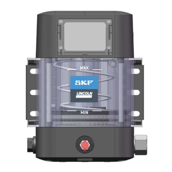
Lincoln SKF CLP Touch Assembly Instructions Manual (72 pages)
Lubrication pump for progressive systems
Brand:
Lincoln
| Category:
Water Pump
| Size: 3 MB
Table of Contents
Original EC Declaration of Incorporation in Accordance with Directive 2006/42/EC, Appendix II Part 1 B
2
Of Machinery (Safety) Regulations 2008 No. 1597 Annex II
2
Masthead
4
Table of Contents
5
Safety Alerts, Visual Presentation, and Layout
7
Safety Instructions
8
General Safety Instructions
8
General Electrical Safety Instructions
8
General Behaviour When Handling the Product
8
Intended Use
8
Persons Authorized to Use the Product
8
Foreseeable Misuse
9
Referenced Documents
9
Prohibition of Certain Activities
9
Painting Plastic Components and Seals
9
Safety Markings on the Product
9
Note on the Type Plate
9
Notes on CE Marking
9
Note on Low Voltage Directive
9
Note on Pressure Equipment Directive
9
Note on UL Mark
10
Note on ECE Mark
10
Note on UKCA Marking
10
Note on EAC Marking
10
Note on China Rohs Mark
10
Emergency Shutdown
10
Assembly, Maintenance, Fault, Repair
10
First Start-Up, Daily Start-Up
10
Residual Risks
11
Lubricants
12
General Information
12
Material Compatibility
12
Temperature Properties
12
Aging of Lubricants
12
Avoidance of Faults and Hazards
12
Solid Lubricants
12
Overview, Functional Description
13
Pump Housing, Upper Part
13
Electrical Connections
13
Reservoir
14
Pump Housing, Lower Part
14
Program Structure
15
Explanation of Icons and Symbols
16
Normal Pump Operation
17
Exiting the Screensaver
17
Triggering Additional Lubrication
17
Displaying Lubrications
18
Displaying the Total Operating Hours and the Date and Time
18
Displaying Pump Information
19
Display the Pump Temperature
19
Displaying Warnings
20
Acknowledging Warnings
20
Displaying Errors
21
Acknowledging Errors
21
Displaying the Current Working Mode
22
Setting Operation of the Pump
23
Changing the Pump Password
23
Setting the Date and Time
24
Time-Controlled Mode
24
Modifying Settings
24
Setting the Lubrication Time and Pause Time
25
Checking the Settings
25
Counter-Controlled Mode
26
Settings
26
Setting the Lubrication Time and the Number of Pulses
27
Checking the Settings
28
Cycle Controlled Mode
29
Modifying Settings
29
Monitoring by the Cycle Switch
30
Deviations in the Cycle Switch Signals
30
Checking the Settings
32
Block Operation
33
Block Operation with Cycle Switch Signal Received
33
Block Operation with no Cycle Switch Signal Received
33
Factory Settings
34
Undo/Redo
34
Technical Data
35
Diagram Relative Duty Cycle
36
Tightening Torques
37
Hydraulic Connection Diagrams
38
Type Identification Code
39
Delivery, Returns, Storage
41
Delivery
41
Return Shipment
41
Storage
41
Storage Temperature Range
41
Storage Conditions for Products Filled with Lubricant
41
Storage Period up to 6 Months
41
Storage Period between 6 and 18 Months
41
Storage Period more than 18 Months
41
Declaration of Decontamination
41
Assembly
42
Mounting Dimensions
42
Assembly Holes
42
Setting the Delivery Rate on Pump Element R
43
Installing the Pressure Relief Valve
43
Connection of the Lubrication Line
43
Electrical Connection
44
Setting/Checking the Working Mode and Parameters of the Pump
44
First Start-Up
45
Inspections before First Start-Up
45
Inspections During First Start-Up
45
Operation
46
Initial Filling of a Pump Delivered Without Lubricant
46
Regular Filling with a Transfer Pump
46
Regular Filling with Cartridge
47
Regular Filling Via the Filler Nipple
47
Triggering Additional Lubrication
47
Maintenance and Repair
48
Maintenance
48
Cleaning
49
Basics
49
Interior Cleaning
49
Exterior Cleaning
49
Cleaning the Vent Pipe
49
Faults, Causes, and Remedies
50
Repairs
53
Replacing Pump Element and Pressure Relief Valve
53
Shutdown, Disposal
53
Temporary Shutdown
53
Permanent Shutdown, Disassembly
53
Disposal
53
Spare Parts and Accessories
54
Pump Elements
54
Pressure Control Valves 270 Bar, Plug-In Type for Tube Ø
54
Pressure Control Valves 270 Bar, Screw-In Type for Tube Ø 6
54
Adapter with Filler Fitting
55
Closure Screw
55
Grease Port, Plug-In
55
Fill Connection, Pivoted
55
Grease Port, Plug-In
56
Filling Connection, Screwable
56
Grease Port with Lubricant Return
56
Grease Port Without Lubricant Return
57
Vent Pipe Assy
57
Mounting Brackets
57
Power Lead
58
Appendix
59
Connection Diagrams
59
Overview of Cables and Possible Connections
60
Terminal Diagram for 7-Pin Bayonet Connector
61
Terminal Diagram for 7-Pin Bayonet Connector with Piston Detector
62
Terminal Diagram for 4-Pin Bayonet Connector
63
Terminal Diagram for Rectangular Connector
64
Terminal Diagram for M12X1 Socket, A-Coded
65
Terminal Diagram for M12X1 Socket, B-Coded
66
Terminal Diagram for M12X1 Plug, A-Coded
67
China Rohs Table
68
Advertisement
Advertisement
Related Products
Lincoln SKF CLP
Lincoln SKF ContiMaster
Lincoln SKF 85859
Lincoln SKF 434-3375
Lincoln SKF 84985
Lincoln SKF 563-5430
Lincoln SKF 82054
Lincoln SKF 85746
Lincoln SKF 85745
Lincoln SKF MGH
Lincoln Categories
Automobile
Water Pump
Welding System
Oven
Tools
More Lincoln Manuals
Login
Sign In
OR
Sign in with Facebook
Sign in with Google
Upload manual
Upload from disk
Upload from URL