Sign In
Upload
Manuals
Brands
Lincoln Electric Manuals
Welding System
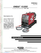
EAGLE SVM192-A
Lincoln Electric EAGLE SVM192-A Manuals
Manuals and User Guides for Lincoln Electric EAGLE SVM192-A. We have
1
Lincoln Electric EAGLE SVM192-A manual available for free PDF download: Service Manual
Lincoln Electric EAGLE SVM192-A Service Manual (95 pages)
Lincoln Electric Portable Generator User Manual
Brand:
Lincoln Electric
| Category:
Welding System
| Size: 1 MB
Table of Contents
Safety
2
Table of Contents
7
Technical Specifications
8
Input
8
Rated Output
8
Physical Dimensions
8
Installation
9
Safety Precautions
9
Spark Arrester
9
Machine Grounding
9
Vehicle Mounting
10
Battery Connections
10
Fuel
10
Welding Output Cables
10
Angle of Operation
11
Lifting
11
Location/Ventilation
11
Stacking
11
Connection of Lincoln Electric Wire Feeders
12
Additional Safety Precautions
12
Welder Operation
12
Welder Output
12
Auxiliary Power
13
Motor Starting
13
Auxiliary Power While Welding
15
Simultaneous Welding and Power
15
Standby Power Connections
15
Connection of Eagle 10,000 to Premises Wiring
16
Operation Section
17
General Description
18
Welder Controls
18
Engine Switch
18
Range Switch
19
Control Dial
19
Starting the Engine
20
Stopping the Engine
20
Break-In Period
20
Welding Process
21
Wire Feed Welding Processes
21
Tig Welding
21
Arc Gouging
21
Summary of Welding Processes
22
Typical Current Ranges
22
Accessories
23
Optional Equipment
24
Recommended Equipment
25
Stick
25
Wire Feed
25
Plasma Cutting
25
Maintenance
27
Engine Oil Change
28
Engine or Refill Capacities
28
Routine Maintenance
28
Oil Filter Change
29
Air Cleaner and Other Maintenance
29
Engine Adjustments
30
Slip Rings
30
Battery
30
Engine Maintenance Parts
30
Major Component Locations
31
Theory of Operation Section
33
Block Logic Diagram
33
How to Use Troubleshooting Guide
38
PC Board Troubleshooting Procedures
39
Rotor Voltage Test
49
Test Description
49
Materials Needed
49
Rotor Resistance Test
51
Location of Rotor Slip Rings
52
Auxiliary and Field Winding Test
55
Location of Leads
56
To Test the 115 VAC Winding
56
To Test the 230 VAC Winding
56
To Test the Field Winding
57
Output Rectifier Bridge Test
59
Location of Output Rectifier Leads
60
Charging Circuit Test
61
Location of Voltage Regulator
62
Engine Throttle Adjustment Test
63
Blower Paddle Marked for Strobe-Tach Method
64
High Idle Adjustment Nut
65
Low Idle Adjustment Nut
65
Oscilloscope Method
66
Vibratach Method
66
High Idle - no Load
67
Machine Loaded
68
Scope Settings
68
Abnormal Open Circuit DC Weld Voltage Waveform
69
Brush Removal and Replacement
71
Printed Circuit Board Removal and Replacement
75
Output Rectifier Bridge Removal and Replacement
79
Output Rectifier Dimensions
80
Engine /Rotor Removal and Replacement
83
Engine and Rotor Removal
85
Engine and Rotor Removed from Stator
86
Retest after Repair
88
Engine Output
88
Welder DC Output
88
Diagram
89
Electrical Diagrams
90
Wiring Diagram - Code 11096 (M20317)
90
Wiring Diagram - Code 11397 - (M21271)
91
Schematic - Complete Machine - Code 11096 (L12259)
92
Schematic - Complete Machine - Code 11397 (L13104)
93
Schematic - Idler/Field Control P.C. Board (L12197)
94
Advertisement
Advertisement
Related Products
Lincoln Electric CLASSIC SVM194-A
Lincoln Electric INVERTEC SVM199-A
Lincoln Electric INVERTEC SVM129-B
Lincoln Electric POWER MIG SVM160-B
Lincoln Electric POWER WAVE 355/405 SVM159-A
Lincoln Electric RANGER 9 SVM 110-A
Lincoln Electric RANGER SVM120-A
Lincoln Electric CLASSIC III SVM 137-A
Lincoln Electric POWER FEED 10M SINGLE/DUAL SVM172-A
Lincoln Electric WIRE-MATIC 255 SVM 119-A
Lincoln Electric Categories
Welding System
Welding Accessories
Flashlight
Wire Feeders
Portable Generator
More Lincoln Electric Manuals
Login
Sign In
OR
Sign in with Facebook
Sign in with Google
Upload manual
Upload from disk
Upload from URL