Sign In
Upload
Manuals
Brands
Lime Microsystems Manuals
Motherboard
LMS6002D
Lime Microsystems LMS6002D Manuals
Manuals and User Guides for Lime Microsystems LMS6002D. We have
1
Lime Microsystems LMS6002D manual available for free PDF download: Quick Start Manual
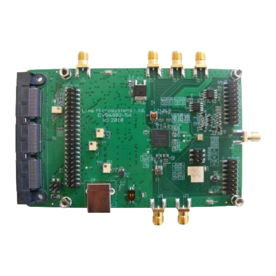
Lime Microsystems LMS6002D Quick Start Manual (91 pages)
Brand:
Lime Microsystems
| Category:
Motherboard
| Size: 4 MB
Table of Contents
Table of Contents
2
1 Introduction
7
2 Development System Contents
8
Figure 1 Development System Contents
8
3 Evaluation Board Connections
9
Basic Connections
9
Board Connections
10
Figure 2 Evaluation Board Connection Descriptions
10
Figure 3 Connector J1 Circuit Diagram
12
J1 - Main Power Supply Connector
12
Figure 4 Connector J2 Circuit Diagram
13
J2 - Third Party Baseband Board Connector
13
Figure 5 Connector J3 Circuit Diagram
14
J3 - Analogue IQ Signals
14
Figure 6 Connector J5 Circuit Diagram
15
J5 - Digital I/O (I&Q) TX 12 Bit & Txiqsel and RX 12 Bit & Rxiqsel
15
J16 - USB Connector
16
J8 - Sourcing 5V Supply from Baseband Board
16
Hardware Options: Clocking, TCXO & SPI
16
Figure 7 Connector J8 Circuit Diagram
16
TCXO Frequency and Data Clocks Distribution
17
Different Clocking Schemes
18
TCXO Locking Options
19
SPI Control Options
20
Figure 8 TXCO Locking and SPI Option Components Location (Top Side)
20
Figure 9 SPI Control Resistor Component Locations
21
4 Installing and Running PC Software Application
22
Windows XP Operating System
22
Figure 10 Hardware Wizard
23
Figure 11 Hardware Wizard. Install Driver Manually
23
Figure 12 Hardware Wizard. Choose the Usbdriver.inf from the Folder
24
Determining Serial Port
25
Figure 13 Check in Device Manager the New Communication Port
25
Windows 7 Operating System
26
Figure 14 Device Manager. Choose the Usbdriver.inf from the Folder
26
Determining Serial Port
27
Figure 15 Check in Device Manager the New Communication Port
27
Turn on and SPI Check
28
Figure 16 Power Supply Reading
28
Figure 17 Run Ctr_6002Dr2 Program as an Administrator
28
Figure 18 GUI Communication Settings
29
Figure 19 GUI Register Test
29
Figure 20 GUI Register Test Log
30
Ctr6002Dr2 - Software Description
31
System Interface
31
Figure 21 GUI System Window
31
Top Level
33
Figure 22 GUI Top Level Window
33
Tx Pll + Dsm
35
Figure 23 GUI Txpll + DSM Window
35
Figure 24 PLL Mode
36
Figure 25 Output Frequency - Ghz
36
Figure 26 Calculated Values for Fractional Mode
37
Figure 27 VCO Capacitance
37
Figure 28 Current VCO and MUX/DIV Selections
37
Figure 29 VCO Capacitance
38
Figure 30 CP Current and Offset
38
Rx PLL + DSM
39
Figure 31 Frequency Versus Capacitance Calibration Table Data
39
Figure 32 RX PLL + DSM Page
40
Figure 33 PLL Mode
41
Figure 34 Setting Receiver Frequency - Ghz
41
Figure 35 Calculated Values for Fractional Mode
42
Figure 36 VCO Capacitance
42
Figure 37 Current VCO and MUX/DIV Selections
42
Figure 38 VCO Capacitance
43
Figure 39 CP Current and Offset
43
Figure 40 Frequency Vs Capacitance Calibration Table Data
43
Tx LPF
44
Figure 41 Tx LPF Page
44
Tx RF
45
Figure 42 Tx RF Page
45
Rx LPF
46
Figure 43 Rx LPF Page
46
Rx Vga2
48
Figure 44 Rx VGA2 Page
48
Rx Fe
49
Figure 45 Rx FE (Front End)
49
Figure 46 LNA Control Setting
50
Adc/Dac
51
Figure 47 MIX Control Settings
51
Figure 48 ADC/DAC Page
52
Figure 49 DAC Enable Control Timing for TX
53
Figure 50 ADC Enable Control Timing for RX
53
Board
54
Figure 51 ADC/DAC Reference Control - Default Settings
54
Figure 52 ADC Control Settings
54
Figure 53 S/W Control for on Board ADF4002 - TCXO Locking
55
5 Transmitter and Receiver Basic Setup
56
Transmitter Setup and Basic Testing
56
Top Level Setting
56
TX LPF & Gain Setting
57
Figure 54 Top Level Settings
57
Figure 55 Setting Tx LPF Bandwidth
57
TX PLL Setup
58
Figure 56 Tx Gain Setting and PA Selection
58
Testing TX Output
59
Figure 57 Tx PLL Setting
59
Figure 58 Basic TX Testing Using DC Offset Resulting in lo Leakage
59
TX Basic Operation Checks
60
Receiver Setup and Basic Testing
61
Top Level Settings
61
Figure 59 Top Level Settings
61
RX LPF & Gain Setting
62
Figure 60 Setting Rx LPF to 7 Mhz
62
Figure 61 Setting Rx VGA2 Gain
62
RX PLL Setup
63
Figure 62 Rx LNA and VGA1 Settings
63
Figure 63 Rx PLL Settings
64
Testing RX Output
65
RX Basic Operation Checks
65
Figure 64 Oscilloscope Capture of 1 Mhz I & Q Sine Wave Outputs
65
6 LMS6002D Calibration Procedures
66
TX lo Leakage Calibration
66
Figure 65 Transmit Output
67
Figure 66 System Window. Use Automated Calibration
67
Figure 67 Transmit Output after Calibration
68
Figure 68 Tx RF Window
68
Transmit I/Q Balance Calibration
69
Figure 69 Transmit Output after Calibration
69
Figure 71 Phase Angle Calibration
70
Figure 70 Initial -1 Mhz Image Spectrum
70
Figure 72 Amplitude Balance Calibration
71
Figure 73 Transmit EVM Performance after Calibration
71
Receiver DC Calibration
72
Figure 74 Rx FE Page
72
Figure 76 Rx VGA2 Tab
73
Figure 75 Rx LPF Tab
73
Figure 77 Receiver lo Leakage
74
Figure 78 Rx VGA1 DC Offset Adjust in RX FE Tab
74
Figure 79 Rx Automatic DC Calibration Result
75
Calibration Process Summary
76
7 Appendix A - Saving and Retrieving SPI Test Setups
77
Saving a Setup
77
Loading *.Prj Files
78
Figure 80 Save Project Feature
78
Figure 81 Open Project
78
Figure 82 Auto Download Feature
79
Figure 83 Download Button for Previously Saved Setup
79
8 Appendix B - Test Systems Connections
80
Basic Setup
80
Figure 84 Test System Connections for Receive and Transmit Testing
80
Transmitter Test System Connections
81
Receive Test System Connections
81
Figure 85 Transmitter Test Setup
81
Figure 86 Receiver Test Setup
81
9 Appendix C - Signal Generator Setup
82
Agilent MXG Setup
82
Figure 87 Agilent N5181A/82A MXG Front Panel
82
Downloading *.Wfm Files to the Signal Generator
85
10 Appendix D - Common Receiver Test Issues
88
Verify the PLL Is Locked
88
Figure 88 Rx PLL VCO Capacitance
89
Figure 89 no Receive Baseband Output
89
Figure 90 Non-Sinusoidal Baseband Output
90
Figure 91 Sinusoidal Baseband Output
90
Is the Correct LNA Selected
91
Is the Correct Rx VGA 2 Gain Selected
91
Advertisement
Advertisement
Related Products
Lime Microsystems LMS7002M Series
Lime Microsystems LMS7002MR3
Lime Microsystems LMS8001
Lime Microsystems LMS8001A
Lime Microsystems LMS8001B
Lime Microsystems Categories
Computer Hardware
Transceiver
Motherboard
More Lime Microsystems Manuals
Login
Sign In
OR
Sign in with Facebook
Sign in with Google
Upload manual
Upload from disk
Upload from URL