Table of Contents
Advertisement
Quick Links
LMS6002D Quick Starter Manual for Evaluation Board
Lime Microsystems Limited
Surrey Tech Centre
Occam Road
The Surrey Research Park
Guildford
Surrey GU2 7YG
United Kingdom
LMS6002D Quick Start Manual
The information contained in this document is subject to change without prior
notice. Lime Microsystems assumes no responsibility for its use, nor for
infringement of patents or other rights of third parties. Lime Microsystems' standard
terms and conditions apply at all times.
© Copyright Lime Microsystems
Rev: 2.2
Last modified: 03/05/2012
Advertisement
Table of Contents

Summary of Contents for Lime Microsystems LMS6002D
- Page 1 The information contained in this document is subject to change without prior notice. Lime Microsystems assumes no responsibility for its use, nor for infringement of patents or other rights of third parties. Lime Microsystems' standard terms and conditions apply at all times.
-
Page 2: Table Of Contents
LMS6002D Quick Starter Manual for Evaluation Board Contents 1 Introduction ..........................7 2 Development System Contents....................8 3 Evaluation Board Connections ....................9 3.1 Basic Connections ......................... 9 3.2 Board Connections ......................10 J1 – Main Power Supply Connector ..............12 3.2.1. - Page 3 LMS6002D Quick Starter Manual for Evaluation Board 5.1.1. Top Level Setting ....................56 5.1.2. TX LPF & Gain Setting ..................57 5.1.3. TX PLL Setup ....................... 58 5.2 Testing TX Output ......................59 5.2.1. TX Basic Operation Checks .................. 60 5.3 Receiver Setup and Basic Testing ..................
- Page 4 LMS6002D Quick Starter Manual for Evaluation Board Table of Figures Figure 1 Development System Contents ..................8 Figure 2 Evaluation board connection descriptions..............10 Figure 3 Connector J1 circuit diagram..................12 Figure 4 Connector J2 circuit diagram..................13 Figure 5 Connector J3 circuit diagram..................14 Figure 6 Connector J5 circuit diagram..................
- Page 5 LMS6002D Quick Starter Manual for Evaluation Board Figure 42 Tx RF page ........................45 Figure 43 Rx LPF page ......................... 46 Figure 44 Rx VGA2 page ......................48 Figure 45 Rx FE (Front End) ......................49 Figure 46 LNA Control setting ..................... 50 Figure 47 MIX Control settings ....................
- Page 6 LMS6002D Quick Starter Manual for Evaluation Board Figure 85 Transmitter test setup ....................81 Figure 86 Receiver test setup ......................81 Figure 87 Agilent N5181A/82A MXG Front Panel ..............82 Figure 88 Rx PLL VCO capacitance .................... 89 Figure 89 No Receive Baseband Output ..................89 Figure 90 Non-sinusoidal baseband Output ..................
-
Page 7: Introduction
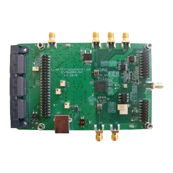
The EVB6002-5 is a general purpose evaluation board intended to allow evaluation and testing of the LMS6002D multi-band, multi-standard RFIC transceiver. It is not intended to act as a guide to the best layout, decoupling and matching practices when implementing the LMS6002D. -
Page 8: Development System Contents
LMS6002D Quick Starter Manual for Evaluation Board Development System Contents Before commencing any work please ensure all of the contents listed below are contained in the system shipped. See below: Figure 1 Development System Contents PC to USB cable USB software stick... -
Page 9: Evaluation Board Connections
An interface via pin header J5 is provided to the parallel digital interface on the LMS6002D. A baseband connector via pin header J2 is also provided to be used with third party basebands. -
Page 10: Board Connections
LMS6002D Quick Starter Manual for Evaluation Board 3.2 Board Connections Figure 2 Evaluation board connection descriptions. The following table describes the high level pin assignment for each connector on the evaluation board. 10 | P a g e © Copyright Lime Microsystems Rev: 2.2... - Page 11 LMS6002D Quick Starter Manual for Evaluation Board Connector Name Description 5V Power 5V supply feed used for standalone operation (not connected to Supply baseband board). The board is shipped in this mode. To run the Lime boards using the power supply from a baseband card connect the links on connector J8 (see connector J8 for details).
-
Page 12: J1 - Main Power Supply Connector
LMS6002D Quick Starter Manual for Evaluation Board RX IN 3 Receiver input RX3, input direct to chip. TX OUT 1 Transmitter output TX1, output direct from the chip. USB Connector to PC. Table 1 Evaluation board connectors 3.2.1. J1 – Main Power Supply Connector Figure 3 Connector J1 circuit diagram. -
Page 13: J2 - Third Party Baseband Board Connector
LMS6002D Quick Starter Manual for Evaluation Board 3.2.2. J2 – Third Party Baseband Board Connector The SAM-QSS-RA-150 is a standard connector used by third party baseband providers. The SAM-QSS-RA-150 is a standard connector used third party baseband providers. The LMS6002D board is shipped... -
Page 14: J3 - Analogue Iq Signals
LMS6002D Quick Starter Manual for Evaluation Board 3.2.3. J3 – Analogue IQ Signals Pins 18 and 20 of J3 connector are single ended analogue receiver outputs. Pins 10, 12, 14 and 16 are differential analogue receiver outputs. Pins 2, 4, 6 and 8 are differential analogue transmitter inputs. -
Page 15: J5 - Digital I/O (I&Q) Tx 12 Bit & Txiqsel And Rx 12 Bit & Rxiqsel
LMS6002D Quick Starter Manual for Evaluation Board 3.2.4. J5 – Digital I/O (I&Q) TX 12 Bit & TXIQSel and RX 12 Bit & RXIQSel The digital I/Q connector is a digital transmit (TX) and receive (RX) interface to the ADC/DAC of the LMS6002D. -
Page 16: J8 - Sourcing 5V Supply From Baseband Board
3.2.6. J16 – USB Connector A type B USB connector is used to connect the PC to the evaluation board. It enables the LMS6002D to be programmed via the 6002Dr2 test GUI software that comes with the Quick Starter kit. -
Page 17: Tcxo Frequency And Data Clocks Distribution
The LMS6002D device provides a flexible clocking scheme which enables the PLL clock, RX clock and TX clock to be independently clocked. The LMS6002D board is shipped with a default mode using the on board 30.72MHz clock provided. The board can be reconfigured to allow users to provide clocking from external devices using the two connectors J2 &... -
Page 18: Different Clocking Schemes
LMS6002D Quick Starter Manual for Evaluation Board The board is shipped in the default mode (Option 1). To use other options please make sure that hardware changes were applied as in the table below. Please note that NF denotes component is not fitted. -
Page 19: Tcxo Locking Options
LMS6002D Quick Starter Manual for Evaluation Board 3.6 TCXO Locking Options The LMS6002D board provides different options to lock the TCXO to base band or test systems. The LMS6002D board provides three options for clock locking: Option 1 – Lock using on board PLL device ADF4002. This is the default mode the board is shipped with to enable the board to be locked to test equipment using an external 10MHz clock provided by connector J4, acting as an input. -
Page 20: Spi Control Options
Figure 8 TXCO locking and SPI option components location (top side) 3.7 SPI Control Options The LMS6002D board can be controlled by using the SPI connectors via J2, J6 or J16. Please note only one SPI master can be connected to the bus at any time, hence these are mutually exclusive. -
Page 21: Figure 9 Spi Control Resistor Component Locations
LMS6002D Quick Starter Manual for Evaluation Board SPI control Option 2 Option 1 USB SPI control via J16 with J2 DEFAULT MODE baseband SPI disabled. Used with 3 Options USB SPI via J16 or baseband party baseband boards and board SPI via J2 controlling LMS6002D with PC S/W via USB. -
Page 22: Installing And Running Pc Software Application
LMS6002D Quick Starter Manual for Evaluation Board Installing and Running PC Software Application 4.1 Windows XP Operating System Plug USB cable to USB port of the interface board. 1. You will need to be logged in as Administrator to the free USB port on your Windows machine. -
Page 23: Figure 10 Hardware Wizard
LMS6002D Quick Starter Manual for Evaluation Board Figure 10 Hardware wizard. Next, you will want to install from a specific location. Figure 11 Hardware wizard. Install driver manually Next, you need to point to the USBDriver.inf file, which can be found in the QuickStarterKit folder. -
Page 24: Figure 12 Hardware Wizard. Choose The Usbdriver.inf From The Folder
LMS6002D Quick Starter Manual for Evaluation Board Figure 12 Hardware wizard. Choose the USBDriver.inf from the folder Windows should proceed to install drivers. Enumeration process (USB term meaning "connect and establish communication with") should start now. If everything is successful unplug and then plug in your device again to be able to use it. -
Page 25: Determining Serial Port
LMS6002D Quick Starter Manual for Evaluation Board 4.2 Determining Serial Port After enumeration (USB term meaning "connect and establish communication with") Windows will assign to your USB Virtual Serial device a serial port - COM?. Right-Click on My Computer, then click Properties, then the Hardware tab, then Device Manager, then find USB Virtual Serial Port under "Ports (COM &... -
Page 26: Windows 7 Operating System
LMS6002D Quick Starter Manual for Evaluation Board 4.3 Windows 7 Operating System Plug USB cable to USB port of the interface board. No external power connection is required. After plugging in the board the USB driver needs to be installed. To install the USB driver do the following: 1. -
Page 27: Determining Serial Port
LMS6002D Quick Starter Manual for Evaluation Board 4.3.1. Determining Serial Port After enumeration (USB term meaning "connect and establish communication with") Windows will assign to your USB Virtual Serial device a serial port - COM?. Click on Control Panel, then click System and Security, then click System, then click Device Manager, then find USB Virtual Serial Port under "Ports (COM &... -
Page 28: Turn On And Spi Check
0.15 Figure 16 Power supply reading Start LMS6002D board control S/W, located in QuickStarterKit transferred from the Lime USB stick. The SPI APP – picture of ICON is shown below. Note: For Window 7 operating system, right click on the “ctr_6002dr2.exe” icon above. Next, click on Properties and click on the “Compatibility”... -
Page 29: Figure 18 Gui Communication Settings
Select enumerated port under USB board. In this case it is COM4 but port may be different Choose desired SPI clock frequency and push OK. Now you are able to communicate with the LMS6002D test board using USB to Serial adapter. To check this is working select the register test sequence by going to menu “Tools->Register Test”. -
Page 30: Figure 20 Gui Register Test Log
If the system returns OK message you are now ready to commence testing. If the system returns 00 or FF instead of the OK this means there is a communication problem with the LMS6002D. If the system test has returned 00 or FF instead of OK then shut down ctr_6002dr2 software and disconnect the Lime interface board. -
Page 31: Ctr6002Dr2 - Software Description
LMS6002D Quick Starter Manual for Evaluation Board 4.5 Ctr6002dr2 – Software Description This section describes the ctr6002dr2 software tool and each of the buttons and embedded controls. Most of the pages in the tool can be read across to the top level sections of the SPI programming map, with the exception of the ‘System page’... - Page 32 LMS6002D Quick Starter Manual for Evaluation Board Bypass configurations The various bypass test modes and loop back test modes can be implemented by selecting from the drop down boxes, default is Normal operation. Automatic Calibration The Automatic calibration buttons can be used to run through the series of SPI commands required to implement the various self-calibration routines provided on the chip.
-
Page 33: Top Level
LMS6002D Quick Starter Manual for Evaluation Board 4.5.2. Top level Various loop back and calibrations are also controlled on this page. They are not needed for basic operation. Automatic calibrations should all be done from the ‘System’ page where macros have been written to apply the calibration routines automatically. - Page 34 LMS6002D Quick Starter Manual for Evaluation Board Power Control Soft turn off of Tx and Rx top level blocks of the LMS6002D via SPI. The LMS6002D communication can be easily checked by toggling the “Soft Tx Enable” and “Soft Rx Enable”...
-
Page 35: Tx Pll + Dsm
LMS6002D Quick Starter Manual for Evaluation Board 4.5.3. TX PLL + DSM The Tx PLL is controlled from this page. If the frequency control on the ‘System Interface’ page is used and the correct ‘set up files’ have been automatically downloaded, then this page should not be needed. -
Page 36: Figure 24 Pll Mode
LMS6002D Quick Starter Manual for Evaluation Board VTUNE_H VTUNE_L Status Vtune is high (> 2.5V) PLL lock not guaranteed. Vtune is Low (< 0.5V) PLL lock not guaranteed. Not possible, check SPI connections. Table 6 Comparator readings Output Buffer Control not used in TxPLL. -
Page 37: Figure 26 Calculated Values For Fractional Mode
LMS6002D Quick Starter Manual for Evaluation Board Figure 26 Calculated Values for Fractional Mode To properly select the ‘VCO Capacitance’ click “Tune” after “Calculate”. If you want to observe the VCO capacitor selection algorithm results select “Log”. Figure 27 VCO Capacitance The ‘Current VCO’... -
Page 38: Figure 29 Vco Capacitance
LMS6002D Quick Starter Manual for Evaluation Board VCO Capacitance Correct setting of VCO capacitance is described in LMS6002D Programming and Calibration Guide. Selections made when using the ‘Calculate’ button however are decided based on the calibration table used in this block. -
Page 39: Rx Pll + Dsm
LMS6002D Quick Starter Manual for Evaluation Board Figure 31 Frequency versus capacitance calibration table data The calibration data consists of frequency versus capacitance value responses which are defined by minimum 2 point definition. The loaded VCO file should contain the above data. If not file ‘Dr2.vco’, provided with SW, should be loaded. -
Page 40: Figure 32 Rx Pll + Dsm Page
LMS6002D Quick Starter Manual for Evaluation Board Figure 32 RX PLL + DSM page Description of each function available from this page is as follows: Decoding Select ‘Decode’ or ‘Direct’ signals for control of different parts of the SPI memory map. -
Page 41: Figure 33 Pll Mode
LMS6002D Quick Starter Manual for Evaluation Board VTUNE_H VTUNE_L Status Vtune is high (> 2.5V), PLL lock not guaranteed. Vtune is Low (< 0.5V), PLL lock not guaranteed. Not possible, check SPI connections. Table 7 Comparator readings Output Buffer Sets the correct PLL output buffer for the selected LNA:... -
Page 42: Figure 35 Calculated Values For Fractional Mode
Figure 37 Current VCO and MUX/DIV selections VCO Capacitance Correct setting of VCO capacitance is described in LMS6002D Programming and Calibration Guide. Selections made when using the ‘Calculate’ button however are decided based on the calibration table used in this block. -
Page 43: Figure 38 Vco Capacitance
LMS6002D Quick Starter Manual for Evaluation Board Figure 38 VCO Capacitance Use of the ‘Calibration’ button is described at the end of this section. Charge Pump(CP) Current and Offset CP Current and Offset is set based on the selected loop filter and loop BW. For the recommended loop filter (implemented on the evaluation board). -
Page 44: Tx Lpf
LMS6002D Quick Starter Manual for Evaluation Board The calibration data consists of frequency versus capacitance value responses which are defined by minimum 2 point definition. The loaded VCO file should contain the above data. If not file ‘Dr2.vco’, provided with SW, should be loaded. To load a new VCO file press the ‘Load’ button and follow the normal windows procedure to load a file. -
Page 45: Tx Rf
LMS6002D Quick Starter Manual for Evaluation Board LPF Bandwidth Set the LPF BW in the drop down box, from 0.75MHz to 14MHz. Note RF system BW is twice this number, i.e. 0.75MHz LPF BW is 1.5MHz system BW. Test Enables LPF bypass for test purposes. Ensure ‘Normal Operation’ is enabled. -
Page 46: Rx Lpf
LMS6002D Quick Starter Manual for Evaluation Board Power Control Powers down stages within the Tx RF block – grayed out controls are accessible via ‘Direct’ decoding mode. Decoding Select ‘Decode’ or ‘Direct’ signals for control of different parts of SPI memory map. When swapping between the 2 options the available options are highlighted (and the unavailable ones grayed out). - Page 47 LMS6002D Quick Starter Manual for Evaluation Board DC Calibration These are the individual controls for the DC correction and auto-calibration routines for the RX LPF (controlled by the ‘Receiver’ auto-calibration button on the ‘System’ page). The Rx LPF DC calibration has 2 stages which can be calibrated: ...
-
Page 48: Rx Vga2
LMS6002D Quick Starter Manual for Evaluation Board 4.5.8. RX VGA2 SPI controls for the RX VGA2 stage settings. Figure 44 Rx VGA2 page Description of each function available from this page is as follows: DC Calibration These are the individual controls for the DC correction and auto-calibration routines for the RX VGA2 (controlled by the ‘Receiver’... -
Page 49: Rx Fe
LMS6002D Quick Starter Manual for Evaluation Board Power Control Powers down the RXVGA2 modules, grayed out controls can be accessed by using direct signals mode. VGA2 Control Sets RXVGA2 Gain, available range is 0 to 30dB in 3dB steps. Decoding is set to ‘Decode Signals’... -
Page 50: Figure 46 Lna Control Setting
LMS6002D Quick Starter Manual for Evaluation Board Decoding Select ‘Decode’ or ‘Direct’ signals for control of different parts of the SPI memory map. When swapping between the 2 options the available options are highlighted (and the unavailable ones grayed out). -
Page 51: Adc/Dac
LMS6002D Quick Starter Manual for Evaluation Board MIX Control Settings for Mix control are shown below, do not change: MIX Bias current – ‘7’, leave it at default. MIX Input – ‘To LNA Out’, leave it at default. -
Page 52: Figure 48 Adc/Dac Page
LMS6002D Quick Starter Manual for Evaluation Board Figure 48 ADC/DAC page Description of each function available from this page is as follows: Decoding Select ‘Decode’ or ‘Direct’ signals for control of different parts of the SPI memory map. When swapping between the two options, the available options are highlighted (and the unavailable ones are grayed out). -
Page 53: Figure 49 Dac Enable Control Timing For Tx
LMS6002D Quick Starter Manual for Evaluation Board See diagram below for explanation: Figure 49 DAC enable control timing for TX Figure 50 ADC enable control timing for RX DAC Edge DAC Edge – selects the edge of the DAC clock which the data is clocked from. Negative is usually required. -
Page 54: Board
LMS6002D Quick Starter Manual for Evaluation Board Use default settings: Figure 51 ADC/DAC Reference control – default settings ADC Control Use default settings with following exceptions: Ref Bias Res Adj = 10uA (minimizes ADC noise) Common mode Adj = 960mV. -
Page 55: Figure 53 S/W Control For On Board Adf4002 - Tcxo Locking
LMS6002D Quick Starter Manual for Evaluation Board Figure 53 S/W control for on board ADF4002 – TCXO locking The default settings will program the standard board with a 30.72MHz TCXO and a 10MHz reference. Using this feature: Press ‘Download All ADF4002 Configuration button’... -
Page 56: Transmitter And Receiver Basic Setup
LMS6002D Quick Starter Manual for Evaluation Board Transmitter and Receiver Basic Setup 5.1 Transmitter Setup and Basic Testing This is a quick check without the need to connect to an external baseband interface. The test using DC to provide LO leakage to test the Tx chain, for accurate repeatable measurements the Baseband Interface (data DACs) should be set to a known state. -
Page 57: Tx Lpf & Gain Setting
LMS6002D Quick Starter Manual for Evaluation Board Figure 54 Top Level Settings Note: The LMS6002 communication can be easily checked by toggling the “Soft Tx Enable” in the Power Control section. The current change can be observed on power supply display. -
Page 58: Tx Pll Setup
LMS6002D Quick Starter Manual for Evaluation Board Select Tx RF page to set gain and select Tx Output. For basic operation select the following VGA1 gain = -10 VGA2 gain = 15 PA1 Selected See diagram below to check selections. -
Page 59: Testing Tx Output
LMS6002D Quick Starter Manual for Evaluation Board Figure 57 Tx PLL setting 5.2 Testing TX Output When transmitter is configures as it showed in section 5.1, one of your selected TX output can be connected to spectrum analyzer (SA). In SA you can now observe the results of this basic operational test. -
Page 60: Tx Basic Operation Checks
LMS6002D Quick Starter Manual for Evaluation Board 5.2.1. TX Basic Operation Checks To check basic TX frequency and gain control conduct some tests changing frequencies and gain settings. The following four tests are recommended: TX RF – VGA 1 change setting from -4 to -35 and observe results. LO should vary by approx 1 dB steps, 31dB range. -
Page 61: Receiver Setup And Basic Testing
LMS6002D Quick Starter Manual for Evaluation Board 5.3 Receiver Setup and Basic Testing Basic functionality checks on the receiver side are achieved by using the analogue output from connector J3, not using the digital output from the data ADCs. 5.3.1. Top Level Settings Using the “Top Level”... -
Page 62: Rx Lpf & Gain Setting
LMS6002D Quick Starter Manual for Evaluation Board 5.3.2. RX LPF & Gain Setting Set LPF bandwidth to 7MHz as illustrated in figure below. Figure 60 Setting Rx LPF to 7 MHz Select ‘Rx VGA2 page’ to set the gain. For basic operation set VGA2 gain = 30. See figure below. -
Page 63: Rx Pll Setup
LMS6002D Quick Starter Manual for Evaluation Board Figure 62 Rx LNA and VGA1 settings 5.3.3. RX PLL Setup Select ‘Rx PLL + DSM’ page to set up the Rx PLL. Please follow the instructions below in the order shown and illustrated in the figure below. -
Page 64: Figure 63 Rx Pll Settings
LMS6002D Quick Starter Manual for Evaluation Board Figure 63 Rx PLL settings 64 | P a g e © Copyright Lime Microsystems Rev: 2.2 Last modified: 03/05/2012... -
Page 65: Testing Rx Output
LMS6002D Quick Starter Manual for Evaluation Board 5.4 Testing RX Output Set the signal generator to 1951MHz (1MHz offset from PLL frequency selected) and input a sine wave at -60dBm into the reference board antenna connector (connector J2). Configure receiver as showed in section 5.3. Connect an oscilloscope to J3.20 or J3.18 on the evaluation board. -
Page 66: Lms6002D Calibration Procedures
This procedure assumes the transmitter has been turned on and initialised, it describes how to then use the parameters within the LMS6002D to cancel any LO leakage from the IQ modulator. It is intended that this will be a single point calibration per band, the example given uses 3GPP Band I with a centre frequency of 2140 MHz. -
Page 67: Figure 65 Transmit Output
LMS6002D Quick Starter Manual for Evaluation Board The output should be observed on the spectrum analyser. The signal on the screen represents the LO feedthru from the transmit modulator. In this case the level is -45dBm Figure 65 Transmit Output Assuming the LPF Core calibration has been carried out in the initialisation then press the ‘Transmitter’... -
Page 68: Figure 67 Transmit Output After Calibration
LMS6002D Quick Starter Manual for Evaluation Board In this case the LO dropped after automatic calibration to -53dBm as shown in Figure 67. Note. Automatic calibration is intended to make the DC zero at the output of the LPF, this is not... -
Page 69: Transmit I/Q Balance Calibration
The value in the box can now be adjusted using the up and down arrows on the key board, once the number has changed the register in the LMS6002D is updated, allowing for a simpler search method. -
Page 70: Figure 71 Phase Angle Calibration
The phase match also depends on the accuracy of the sin/cosine split on the LO of the IQ modulator (inside the LMS6002D), the bulk of the phase correction is for this parameter – hence, amplitude mismatch will vary little with frequency, however phase mismatch may be quite different for each band. -
Page 71: Figure 72 Amplitude Balance Calibration
LMS6002D Quick Starter Manual for Evaluation Board The result of the amplitude balance calibration is seen. The unwanted sideband has been reduced to <-80dBm (-64dBc). The optimum value found in this case was 0.11 dB. If necessary repeat the phase and amplitude adjustments until the optimum values are found and an EVM ≤... -
Page 72: Receiver Dc Calibration
LMS6002D Quick Starter Manual for Evaluation Board Note: The EVM is dependent on a number of parameters being set up correctly. Phase noise performance of the LO is dominant factor in the above measurement. 6.3 Receiver DC Calibration The receiver has a number of self-calibration routines which are designed to cancel out DC offsets from the LPF’s and the VGA’s. -
Page 73: Figure 76 Rx Vga2 Tab
LMS6002D Quick Starter Manual for Evaluation Board 3. In ‘Rx LPF’ Tab, press “Reset Calibration”. Figure 75 Rx LPF tab 4. In ‘Rx VGA2’ Tab, Press “Reset Calibration”. Figure 76 Rx VGA2 Tab DC Leakage after Calibration Reset. DC offset very large – would prevent automatic DC calibration. -
Page 74: Figure 77 Receiver Lo Leakage
LMS6002D Quick Starter Manual for Evaluation Board Figure 77 Receiver LO leakage 5. RXVGA1 Offset Optimisation In ‘RX FE’ tab, slightly adjust the RXVGA1 DC offset values to reduce the DC offset. Figure 78 Rx VGA1 DC Offset Adjust in RX FE Tab 6. -
Page 75: Figure 79 Rx Automatic Dc Calibration Result
LMS6002D Quick Starter Manual for Evaluation Board Figure 79 Rx automatic DC calibration result 75 | P a g e © Copyright Lime Microsystems Rev: 2.2 Last modified: 03/05/2012... -
Page 76: Calibration Process Summary
LMS6002D Quick Starter Manual for Evaluation Board 6.4 Calibration Process Summary There are several similarities between receive and transmit DC calibration process but one fundamental difference. During the transmit calibration process no signal can be applied to the input of the transmitter. An automated DC calibration is performed to ensure the BB stages contribute no DC offset to the LO leakage calibration. -
Page 77: Appendix A - Saving And Retrieving Spi Test Setups
Appendix A – Saving and Retrieving SPI Test Setups The LMS6002D chip set up can be stored in a *.prj file and used in the future. The Save Project feature of the software tool allows all the SPI settings to be saved for future use. -
Page 78: Loading *.Prj Files
LMS6002D Quick Starter Manual for Evaluation Board Figure 80 Save Project feature 7.2 Loading *.prj Files A *.prj file can be loaded using the standard windows procedure as shown below. Figure 81 Open project 78 | P a g e ©... -
Page 79: Figure 82 Auto Download Feature
LMS6002D Quick Starter Manual for Evaluation Board Select File – Open Project – then select the project that was previously saved from the window file box. When loading files the software GUI tool can be setup to either load variables into the tool, but not download them to the chip or to download the variable into the tool and auto download them. -
Page 80: Appendix B - Test Systems Connections
LMS6002D Quick Starter Manual for Evaluation Board Appendix B - Test System Connections 8.1 Basic Setup Spectrum Analyser (+VSA) Power Supply Signal TX 1 RF Generator LMS600 2 Test I&Q RX I/Q (Single Block Board ended) RX 1 Oscilloscope SPI TRX... -
Page 81: Transmitter Test System Connections
LMS6002D Quick Starter Manual for Evaluation Board 8.2 Transmitter Test System Connections MXA N9020A MS06054A Figure 85 Transmitter test setup 8.3 Receive Test System Connections MXA N9020A MS06054A Figure 86 Receiver test setup 81 | P a g e © Copyright Lime Microsystems Rev: 2.2... -
Page 82: Appendix C - Signal Generator Setup
LMS6002D Quick Starter Manual for Evaluation Board Appendix C – Signal Generator Setup This manual uses the Agilent N5182A MXG signal generator with an arbitrary waveform generator and the differential I/Q outputs option (1EL). Other signal generators can be used. - Page 83 Cables and connections should not be moved once I/Q gain and phase calibration is completed. In practice the LMS6002D chip will be soldered to a PCB and connected to a baseband processor so this is purely a test issue.
- Page 84 Agilents ‘Signal Studio’ program or test vectors which can be generated independently via ‘Matlab’ or C. Lime has a number of test vector files which are used for test and calibration of the LMS6002D as follows: DC.wfm - DC tone for TX CW testing (clock 52MHz).
-
Page 85: Downloading *.Wfm Files To The Signal Generator
LMS6002D Quick Starter Manual for Evaluation Board 19. Type in required scaling factor e.g.25%, type ’25’ on number pad and press ‘%’ softkey (3. softkey 1). Note – even if text next to ‘scaling’ softkey already states 25% (for example) this does not mean it has been applied to the waveform, still follow process. - Page 86 LMS6002D Quick Starter Manual for Evaluation Board o Set subnet mask to same as sig gen, in this case 255.255.255.0 o Press ok on both open dialog boxes. Open a Command Prompt window o Start o All programs o Accessories o Command Prompt ...
- Page 87 LMS6002D Quick Starter Manual for Evaluation Board If you are correctly connected the above should be returned. Press ‘return’ twice (for user name and password – none needed) Type ‘cd bbg1’ Type ‘cd waveform’ Type ‘bin’...
-
Page 88: Appendix D - Common Receiver Test Issues
LMS6002D Quick Starter Manual for Evaluation Board Appendix D - Common Receiver Test Issues If there is no baseband signal output from the receiver there are a number of things to check. 10.1 Verify the PLL is locked. The set up file provided with the test board should have the correct settings so that the synthesizers lock at all available frequencies. -
Page 89: Figure 88 Rx Pll Vco Capacitance
As soon as the number is change it is downloaded to the LMS6002D so scrolling through and observing the effect is quite fast. There are 3 types of display on the scope that can occur when doing this testing. -
Page 90: Figure 90 Non-Sinusoidal Baseband Output
LMS6002D Quick Starter Manual for Evaluation Board 2. Non-sinusoidal baseband output as shown below. This occurs when the synthesizer is close to the desired frequency but not locked. This type of behavior usually occurs close to the desired VCO capacitor value. -
Page 91: Is The Correct Lna Selected
LMS6002D Quick Starter Manual for Evaluation Board If all capacitor values are tried and display B is achieved with a mid range value, but the synthesiser does not subsequently lock then there may be a problem. Please contact Lime for assistance.
Need help?
Do you have a question about the LMS6002D and is the answer not in the manual?
Questions and answers