Sign In
Upload
Manuals
Brands
Liebert Manuals
Power Supply
CHALLENGER 3000
Liebert CHALLENGER 3000 Manuals
Manuals and User Guides for Liebert CHALLENGER 3000. We have
2
Liebert CHALLENGER 3000 manuals available for free PDF download: Operation And Maintenance Manual, User Manual
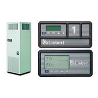
Liebert CHALLENGER 3000 Operation And Maintenance Manual (76 pages)
3 & 5 Ton, 50 & 60Hz
Brand:
Liebert
| Category:
Air Conditioner
| Size: 4 MB
Table of Contents
Table of Contents
3
1 Introduction
9
System Descriptions
9
Compressorized Systems
9
GLYCOOL™ (Chilled Glycol Cooling) Systems
9
Chilled Water Systems
9
Start-Up Procedure
10
2 Operation with Advanced Microprocessor Controls
11
Basics
11
Figure 1 Advanced Microprocessor Control Panel
11
Figure 2 Advanced Microprocessor (A) Control for Challenger 3000
12
Status Display
13
Main Menu <MENU/ESC
13
Status/Alarm Data
13
Active Alarms
13
Operating Status
13
Alarm History Log
13
Run Hours Log
14
Analog Sensors
14
Setpoints/Setup
14
View Setpoints
14
Table 1 Default Setpoints and Ranges
14
Setup System
15
Setup Operation
15
Table 2 Setup Functions, Default Values and Ranges
16
Select Options
16
Calibrate Sensors
16
Show DIP Switches
16
Table 3 Unit Options
16
Table 4 DIP Switch Settings
16
Setup Alarms
17
Table 5 Alarm Default Time Delays
17
Table 7 Alarm Default Time Delays
17
Humidity (HUM) Control Method
18
Standard Custom Alarm Messages
18
Analog Setup
19
Calibrate Actuator
19
Set Status Display
19
Run Diagnostics
20
Show Inputs
20
Test Outputs
20
Test Control Board
20
Change Passwords
21
Date and Time
21
Status Display
21
Control Circuit Board
21
LCD Display Contrast
21
Non-Volatile Memory
22
DIP Switches
22
Control Outputs
22
Table 6 Control Output Leds
22
3 Operation with Advanced Microprocessor with Graphics Control
23
Basics
23
Figure 3 Advanced Microprocessor with Graphics (G) Control Panel
23
Figure 4 Advanced Microprocessor with Graphics Control Menu
24
Status Display
25
Main Menu <MENU/ESC
25
View/Set Alarms
25
Active Alarms
25
Alarm History Log
25
Setup Alarms
26
Setup Custom Alarms
27
View Water Detect Floor Plan (for Optional LTM1000/LT750)
27
Setup Water Detect Floor Plan
27
Operating Status
28
View/Set Control Setpoints
28
Table 8 Default Setpoints and Ranges
28
System Setup
28
Setup Operation
28
Cold Start Delay
28
Table 9 Setup Functions, Default Values and Ranges
29
Select Options
30
Calibrate Sensors
30
Calibrate Valve Actuator
30
Select Control Algorithm (Chilled Water and SCR Reheats Only)
30
Table 10 Unit Options
30
Select Humidity Sensing Mode
31
Set Status Display
31
Change Passwords
31
Run Diagnostics
31
Show Inputs
32
Test Outputs
32
Test Control Board
32
DIP Switches
33
Date and Time
33
Plot Graphs
33
Modify Plot Scales
33
Table 11 Setting Options
33
Analog/Digital Inputs
34
Read Analog Inputs
34
Setup Analog Inputs
34
Read Digital Inputs
34
Setup Digital Inputs
34
View Run Hours Log
34
3.12.1 View 24 Hour Run Time History
35
3.12.2 View Total Run Hours
35
Control Circuit Board
35
3.13.1 LCD Contrast
35
3.13.2 Nonvolatile Memory
36
3.13.3 DIP Switches
36
3.13.4 Control Outputs
36
Table 12 Control Output Leds
36
4 System Performance with Advanced Microprocessor Controls
37
Temperature Control
37
Cooling/Heating Required, in Percent (%)
37
Response to Control Types
37
Intelligent Control (Chilled Water Only)
37
Cooling Operation
38
Table 13 Cooling/Dehumidification Load Status Response
38
Dual Cooling Source
38
Heating Operation
39
Humidity Control
39
Dehumidification/Humidification Required, in Percent
39
Response to Control Types
39
Dehumidification Operation
39
Humidification Operation
40
Control Types
40
Proportional Control
40
PID Control (Chilled Water or SCR Reheats Only)
40
Intelligent Control (Chilled Water Only)
41
Table 15 Additional Connections Available after Unit Delivery
42
Load Control Features
42
Short Cycle Control
42
Sequential Load Activation Control
42
Additional Features
42
Connecting the Analog Sensors
42
Table 14 Analog Input Terminals
42
Table 15 Table
42
Table 24 Table
42
Figure 5 Analog Input Jumpers
43
Water Detection Display
43
Installation-LT750 DIP Switch Settings
43
Figure 6 Connecting the LT750
43
Physical Connections
44
Communications
45
5 Alarm Descriptions
46
Standard Alarms
46
Change Filter
46
Compressor Overload
47
Custom Alarms
47
High Head Pressure
47
High Humidity
47
High Humidity and Low Humidity (Simultaneously)
47
High Temperature
47
High Temperature and Low Temperature (Simultaneously)
48
Humidifier Problem
48
Loss of Air Flow
48
Loss of Power
48
Low Humidity
48
Low Suction Pressure
48
Low Temperature
48
Main Fan Overload
48
Short Cycle
49
Optional/Custom Alarms
49
Loss of Water Flow
49
Smoke Detected
49
Standby GC Pump on
49
Standby Unit on
49
Water under Floor
49
6 Component Operation and Maintenance
50
System Testing
50
Environmental Control Functions
50
Smoke Detector
51
Water Detection Sensor
51
Figure 7 Liebert Leak Detection Units
51
Figure 8 Recommended Liquid Sensor Locations
51
Table 16 Zone Leak Detection Kit Installation Scenarios
52
Table 26 Table
52
Remote Shutdown
52
Filters
52
Blower Package
53
Fan Impellers and Bearings
53
Belt
53
Air Distribution
53
Table 17 Recommended Free Area Ft 2 (M 2 ) for Grilles or Perforated Panels at Output Velocities
53
Refrigeration System
54
Suction Pressure
54
Discharge Pressure
54
Superheat
54
Table 18 Suction Pressures
54
Table 19 Discharge Pressures
54
Thermostatic Expansion Valve
55
Hot Gas Bypass Valve
55
Operation
55
Air Cooled Condenser
56
Checking Refrigerant Charge (Lee-Temp/Flood Back Head Pressure Control)
56
Figure 9 Outdoor Fan/Condenser Configuration
56
Water/Glycol Cooled Condensers
57
Regulating Valve
57
Figure 10 Johnson Controls Valve Adjustment
57
Figure 11 Metrex Valve Adjustment
58
Glycol Solution Maintenance
58
Valve Disassembly
58
Compressor Functional Check
59
Compressor Replacement
59
Mechanical Failure
59
Electrical Failure
60
Compressor Replacement Procedure
60
Humidifier
61
Infrared Humidifier
61
Cleaning the Pan
61
Changing Humidifier Lamps
61
Figure 12 Infrared Humidifier Lamps
61
Steam Generating Humidifier
62
Figure 13 Steam Generating Humidifier
62
Replacing the Canister
64
Table 20 Humidifier Canister Part Numbers
64
Figure 14 Canister Replacement
65
Circuit Board Adjustments
65
7 Troubleshooting
66
Table 21 Blower Troubleshooting
66
Table 22 Chilled Water Troubleshooting
66
Table 23 Compressor and Refrigeration System Troubleshooting
67
Table 24 Dehumidification Troubleshooting
69
Table 25 Glycol Pump Troubleshooting
69
Table 26 Infrared Humidifier Troubleshooting
69
Table 27 Steam Generating Humidifier Troubleshooting
70
Table 28 Reheat Troubleshooting
71
8 Monthly Maintenance Inspection Checklist
72
9 Semiannual Maintenance Inspection Checklist
73
Advertisement
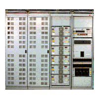
Liebert CHALLENGER 3000 User Manual (59 pages)
DC Power System
Brand:
Liebert
| Category:
Power Supply
| Size: 1 MB
Table of Contents
Table of Contents
3
1 About this Document
7
About Thi Document
7
Applicability of this Document
7
Purpose of this Document
7
Description
8
Figure 1 Front View of a Typical Bottom Fed 4000 a Helios DC System 4000/48 Power System
8
2 Introduction
8
Applications
9
Figure 2 Front View of a Typical 6000 a Helios DC System 4000/48 Power System
9
Control and Distribution Cabinets - Typical Configurations
10
Figure 3 Typical Configurations for Helios DC System 4000/48 Control, Distribution and Rectifier Cabinets
10
Table 1 Rectifier Cabinets
11
Table 2 Control and Distribution Cabinets
11
Table 3 Auxiliary Distribution Cabinets
11
Framework
12
Mechanical Specifications of a Cabinet
12
Electrical Specifications of the Cabinets
12
Table 4 Mechanical Specifications of the Cabinet (Empty)
12
3 Specifications
12
Conventional Controller
13
Mechanical Specifications of the Conventional Controller
13
Electrical Specifications of the Conventional Controller
13
Figure 4 Front View of the Conventional Controller
13
Table 5 Mechanical Specifications of the Conventional Controller
13
Distribution Panels
14
Fuse Panels
14
Figure 5 Front View of the 20 QFF 0-5 a Fuse Panels
14
Table 6 Mechanical Specifications of the Fuse Panels
14
Table 7 Fuse Sizes Available for the (20) QFF 0-5 a Fuse Panels
14
Figure 6 Front View of the (16) QFF 0-5 a & (12) ABS 5-30 a Fuse Panels
15
Figure 7 Front View of the (16) QFF 0-5 a & (6) TPN 5-30 a Fuse Panels
15
Table 8 Fuse Sizes Available for the (16) QFF 0-5 a & (12) ABS 5-30 a Fuse Panels
15
Table 9 Fuse Sizes Available for the (16) QFF 0-5 a & (6) TPN 5-30 a Fuse Panels
15
Figure 8 Front View of the (8) TPN 5-30 a Fuse Panels
16
Figure 9 Front View of the (4) RS100P 70-100 a Fuse Panels
16
Table 10 Fuse Sizes Available for the (8) TPN 5-30 a Fuse Panels
16
Table 11 Fuse Sizes Available for the (4) RS100P 70-100 a Fuse Panels
16
Figure 10 Front View of the (4) CRS200P 150-200 a
17
Figure 11 Front View of the (4) TPL 225-600 a Fuse Panels
17
Table 12 Fuse Sizes Available for the (4) CRS200P 150-200 a
17
Table 13 Fuse Sizes Available for the (4) TPL 225-600 a Fuse Panels
17
Figure 12 Front View of the (18) TPS 1-70 a Fuse Panel
18
Table 14 Fuse Sizes Available for the (18) TPS 1-70 a Fuse Panel
18
Circuit Breaker Panels
19
Table 15 Electrical Specifications of the Fuse Panels
19
Table 16 Mechanical Specifications of the Circuit Breaker Panels
19
Figure 13 Front View of the (24) Plug-In 1-100 a Circuit Breaker Panel
20
Table 17 Plug-In Circuit Breakers Available for the (24) Plug-In 1-100 a Circuit Breaker Panel
20
Figure 14 Front View of the (4) 70-250 a Circuit Breaker Panel
21
Table 18 Circuit Breaker Sizes Available for the (4) 70-250 a Circuit Breaker Panel
21
Figure 15 Front View of the (2) 400 a Circuit Breaker Panel
22
Figure 16 Front View of the (1) 600-700 a Circuit Breaker Panel
22
Table 19 Circuit Breaker Kits Available for the (2) 400 a Circuit Breaker Panel
22
Table 20 Circuit Breaker Kits Available for the (1) 600-700 a Circuit Breaker Panel
22
Table 21 Electrical Specifications of the Circuit Breaker Panels
23
Externally Mounted Battery Return Busbar
24
Mechanical Specifications of the External Battery Return Busbar
24
Electrical Specifications of the External Battery Return Busbar
24
Figure 17 Top and Side Views of the External Battery Return Busbar
24
Table 22 Mechanical Specifications of a Single Lamination
24
Figure 18 Perspective View of the a Terminating Assemblies
25
Terminating Assemblies (Optional)
25
MPS300 and MPA100 Power Shelves
26
Mechanical Specifications of the MPS300 and MPA100 Power Shelves
26
Figure 19 Front View of the MPS300 Power Shelf (Shown Empty)
26
Table 23 Mechanical Specifications of the MPS300 and MPA100 Power Shelves
26
Electrical Specifications of the Power Shelves
27
Rectifiers
27
Helios Rectifier 100/48
27
Figure 20 Front View of the MPA100 Power Shelf (Shown Empty)
27
Figure 21 Front View of the Helios Rectifier 100/48
27
Table 24 Mechanical Specifications of the Helios Rectifier 100/48
27
Helios Rectifiers 200I/48 and 200E/48
28
Table 25 Electrical Specifications of the Helios Rectifier 100/48
28
Table 26 Mechanical Specifications of the Helios Rectifiers 200I/48 and 200E/48
28
Figure 22 Front View of the Helios Rectifiers 200I/48 and 200E/48
29
Electrical Specifications of the Helios Rectifiers 200I/48 and 200E/48
30
Standards
30
Table 27 Electrical Specifications of the Helios Rectifiers 200I/48 and 200E/48
30
600 A and 1200 a Battery Disconnect Unit (Optional)
31
Figure 23 Front View of the Helios Monitor 3000/48 (Without the Mounting Brackets)
31
Figure 24 600 a Battery Disconnect Unit
31
Helios Monitor 3000/48 (Optional)
31
Mechanical Specifications
31
Electrical Specifications
31
Table 28 Mechanical Specifications of the Helios Monitor 3000/48
31
AC Junction Box
32
3.10.1 Mechanical Specifications
32
3.10.2 Electrical Specifications
32
Overall Power System Specifications
32
3.11.1 Standards
32
Mechanical Specifications of Fully Equipped Power Cabinets
32
Figure 25 Front View of the AC Junction Box (with the Front Panel Open)
32
Table 29 Mechanical Specifications of the AC Junction Box
32
Table 30 Mechanical Specifications of Fully Equipped Power Cabinets
32
3.11.3 Electrical Specifications
33
3.11.4 Environmental Specifications
33
3.11.5 Floor and Point Loading
33
Table 31 Floor and Point Loading
33
Conventional Controller
34
Front Panel
34
Figure 26 Front View of the Conventional Controller
34
Table 32 Visual Indicators
34
Table 33 Transmitted Alarms
35
Table 34 Potentiometers
35
Table 35 Switches
36
Table 36 DIP Switch Modules
36
Dip Switches
36
Figure 27 Shunt Range Selection Settings
36
Table 37 Fuse
37
Table 38 Test Points
37
Figure 28 Equalize Voltage and Duration Settings
37
General
34
4 Operation
34
Fuse
37
Test Points
37
Rear Panel
38
Figure 29 Terminal Blocks and Connectors Layout at the Rear of the Conventional Controller
38
Figure 30 Wiring Diagram and Pin Assignment of Terminal Blocks TB1 to TB4
39
Figure 31 Wiring Diagram and Pin Assignment of Terminal Blocks TB5 and TB6, and
40
MPS300 and MPA100 Power Shelves
40
AC Junction Box
41
Distribution Panels
41
Rectifiers
41
Terminating Assemblies (Optional)
41
600 A and 1200 Battery Disconnect Units (Optional)
42
Helios Monitor 3000/48 (Optional)
42
General
43
Helios Monitor 3000/48
43
Controller and Rectifiers
43
Air Filter Replacement
44
Fan Unit Replacement
44
5 Maintenance
43
Table 39 Fault Diagnosis
45
Troubleshooting
45
Addition / Replacement Procedures
46
Addition or Replacement of a Rectifier
46
Figure 32 AC Connections in a Helios Rectifier 200E/48
48
Figure 33 AC Connections in the Female Receptacle for a Helios Rectifier 200I/48 or
49
Figure 34 AC Connections Inside the Junction Box (Top Fed Shown) for a Helios Rectifier 200E/48
49
Figure 35 AC Cable Routing for the Helios Rectifiers 200E/48 in a Top Fed System
50
Figure 36 AC Cable Routing for the Helios Rectifiers 200E/48 in a Bottom Fed System
50
Replacing a Rectifier
51
Adding or Replacing a Battery String
53
Replacement of a Distribution Fuse Block or Circuit Breaker
54
Replacing a Cabinet Alarm Lamp
54
6 Reference Documents
55
7 List of Terms
56
Technical Support
59
Advertisement
Related Products
Liebert Series 300
Liebert 311
Liebert 331
Liebert 341
Liebert 346
Liebert 356
Liebert 361
Liebert 366
Liebert 376
Liebert 381
Liebert Categories
UPS
Air Conditioner
Power Supply
Surge Protector
Chiller
More Liebert Manuals
Login
Sign In
OR
Sign in with Facebook
Sign in with Google
Upload manual
Upload from disk
Upload from URL