Sign In
Upload
Manuals
Brands
Lenovo Manuals
Server
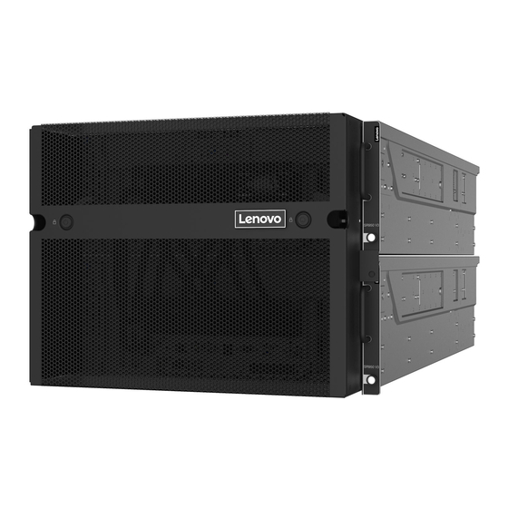
ThinkSystem SR950 V3
Lenovo ThinkSystem SR950 V3 Rack Server Manuals
Manuals and User Guides for Lenovo ThinkSystem SR950 V3 Rack Server. We have
3
Lenovo ThinkSystem SR950 V3 Rack Server manuals available for free PDF download: User Manual, Manual, System Configuration Manual
Lenovo ThinkSystem SR950 V3 User Manual (346 pages)
Brand:
Lenovo
| Category:
Server
| Size: 50 MB
Table of Contents
Table of Contents
3
Safety
7
Safety Inspection Checklist
8
Chapter 1. Introduction
11
Features
11
Tech Tips
12
Security Advisories
13
Specifications
13
Technical Specifications
13
Mechanical Specifications
16
Environmental Specifications
17
Particulate Contamination
18
Management Options
19
Chapter 2. Server Components
23
Front View
23
Rear View
27
Top View
28
Upper Processor Board (CPU BD) Connectors
29
Upper Processor Board (CPU BD) Switches
30
System I/O Board and Interposer Assembly Connectors
32
System I/O Board and Interposer Assembly Switches
33
Lower Processor Board (MB) Connectors
34
Lower Processor Board (MB) Switches
35
System Leds and Diagnostics Display
38
Chapter 3. Parts List
41
Power Cords
43
Chapter 4. Unboxing and Setup
45
Server Package Contents
45
Identify the Server and Access the Lenovo Xclarity
45
Controller
45
Server Setup Checklist
48
Chapter 5. Hardware Replacement Procedures
51
Installation Guidelines
51
Safety Inspection Checklist
52
System Reliability Guidelines
53
Working Inside the Server with the Power on
53
Handling Static-Sensitive Devices
54
Memory Module Installation Rules and Order
54
Independent Memory Mode Installation Order
57
Memory Mirroring Mode Installation Order
59
Power on and Power off the Server
59
Power on the Server
59
Power off the Server
60
Server Replacement
60
Remove the Server from Rails
60
Install the Server to Rails
69
Remove the Rails from the Rack
79
Air Baffle Replacement
81
Remove the Upper Processor Board (CPU BD) Air Baffle
81
Install the Upper Processor Board (CPU BD) Air Baffle
83
Remove the Lower Processor Board (MB) Air Baffle
85
Install the Lower Processor Board (MB) Air Baffle
86
CMOS Battery (CR2032) Replacement
88
Remove the CMOS Battery (CR2032)
88
Install the CMOS Battery (CR2032)
91
Drive Replacement
93
Remove a Hot-Swap Drive
93
Install a Hot-Swap Drive
96
Drive Backplane Replacement
98
Remove a Drive Backplane
98
Install a Drive Backplane
100
Drive Cage Replacement
101
Remove a Drive Cage
101
Install a Drive Cage
103
E3.S Cable Assembly Replacement
105
Remove an E3.S Cable Assembly
105
Install an E3.S Cable Assembly
106
EIA Flange Replacement
107
Remove an EIA Flange
107
Install an EIA Flange
108
Ethernet Port Assembly Replacement
109
Remove the Ethernet Port Assembly
109
Install the Ethernet Port Assembly
111
Fan and Fan Cage Replacement
113
Remove a Fan Module
113
Remove the Fan Cage
114
Install the Fan Cage
116
Install a Fan Module
118
Flash Power Module Replacement
119
Remove a Flash Power Module
119
Install a Flash Power Module
121
Front Operator Panel Replacement
123
Remove the Front Operator Panel
123
Install the Front Operator Panel
125
Intrusion Switch Replacement
128
Remove the Top Cover Intrusion Switch
128
Install the Top Cover Intrusion Switch
129
Remove the Front Intrusion Switch
131
Install the Front Intrusion Switch
133
Lower Processor Board (MB) Replacement (Trained Technician Only)
135
Remove the Lower Processor Board (MB)
135
Install the Lower Processor Board (MB)
140
Read "Installation Guidelines
140
Work Safely
140
Disconnect the Power Cords from the Secondary Chassis. See "Power off the Server" on Page
140
An Electrostatic-Discharge Wrist Strap or Other Grounding System
140
And "Safety Inspection Checklist
140
To Ensure that You
140
M.2 Drive and M.2 Boot Adapter Replacement
144
Remove an M.2 Drive
144
If the Server Is Installed in a Rack, Remove the Server from the Rack. See "Remove the Server from Rails" on Page
144
Step 1. Make Preparation for the Task
145
Remove the Front Top Cover. See "Remove the Front Top Cover" on Page
145
Remove the M.2 Boot Adapter
146
Install the M.2 Boot Adapter
148
Adjust the M.2 Retainer
150
Install an M.2 Drive
153
Memory Module Replacement
156
Remove a Memory Module
156
Remove the Upper Processor Board (CPU BD) Air Baffle. See "Remove the Upper Processor Board (CPU BD) Air Baffle" on Page
157
Install a Memory Module
158
Remove the Upper Processor Board (CPU BD). See "Remove the Upper Processor Board (CPU BD)" on Page
158
Microsd Card Replacement
161
Remove the Microsd Card
161
Install the Microsd Card
162
OCP Module and Cage Replacement
164
Remove the OCP Module
164
Remove the OCP Cage
165
Install the OCP Cage
167
Install the OCP Module
169
Pcie Adapter Replacement
171
Remove a Pcie Adapter
171
Install a Pcie Adapter
174
Pcie Riser Card Replacement
178
Remove the Pcie Riser Card
178
Install the Pcie Riser Card
181
Power Distribution Board Replacement
185
Remove the Power Distribution Board
185
Install the Power Distribution Board
188
Power Interposer Board Replacement
191
Remove the Power Interposer Board
191
Install the Power Interposer Board
193
Power Supply Unit Replacement
194
Remove a Hot-Swap Power Supply Unit
194
Install a Hot-Swap Power Supply Unit
196
Processor and Heat Sink Replacement (Trained Technician Only)
198
Remove a Processor and Heat Sink
198
Sink
202
Install a Processor and Heat Sink
204
Security Bezel Replacement
210
Remove the Security Bezel
210
Install the Security Bezel
211
Serial Port Assembly Replacement
214
Remove the Serial Port Assembly
214
Install the Serial Port Assembly
215
Sideband Card Replacement
217
Remove the Sideband Card
217
Install the Sideband Card
219
Support Bracket Replacement
221
Remove the Support Bracket
221
Install the Support Bracket
223
System I/O Board and Interposer Board Replacement (Trained Technician Only)
224
Module
224
Module
226
Board
228
Board
233
Update the Vital Product Data (VPD)
239
Hide/Observe TPM
240
Update the TPM Firmware
241
Enable UEFI Secure Boot
242
Top Cover Replacement
243
Remove the Front Top Cover
243
Remove the Rear Top Cover
245
Install the Rear Top Cover
246
Install the Front Top Cover
249
UPI Module Replacement
251
Remove the UPI Module
251
Install the UPI Module
254
Upper Processor Board (CPU BD) Replacement
257
Install the Upper Processor Board
262
Complete the Parts Replacement
266
Chapter 6. Internal Cable Routing
269
Identifying Connectors
269
2.5-Inch Drive Backplane Connectors
269
Upper Processor Board (CPU BD) Connectors for Cable Routing
269
System I/O Board and Interposer Assembly Connectors for Cable Routing
270
Cable Routing
271
Power Distribution Board Connectors
272
Pcie Riser Connectors
273
2.5-Inch Drive Backplane Cable Routing
273
E3.S Cable Assembly Cable Routing
276
Ethernet Port Assembly Cable Routing
277
OCP Cable Routing
278
Riser Card Cable Routing
279
Chapter 7. System Configuration
283
Controller
283
Connection
284
Update the Firmware
285
Configure the Firmware
288
Memory Module Configuration
289
Enable Software Guard Extensions (SGX)
290
RAID Configuration
290
Deploy the Operating System
291
Single-Server
292
Back up the Server Configuration
292
Management Processor
292
Chapter 8. Problem Determination
293
Event Logs
293
Display
295
Drive Leds
295
Front Operator Panel Leds
295
Power Supply Leds
297
Upper Processor Board (CPU BD) Leds
298
System I/O Board Leds
299
Lower Processor Board (MB) Leds
301
Firmware and Rot Security Module Leds
302
XCC System Management Port Leds
303
External Diagnostics Handset
304
General Problem Determination Procedures
309
Resolving Suspected Power Problems
310
Resolving Suspected Ethernet Controller Problems
310
Troubleshooting by Symptom
311
Intermittent Problems
311
Problems
313
Memory Problems
314
Monitor and Video Problems
315
Network Problems
317
Observable Problems
317
Could Not Log in Using LDAP Account with SSL Enabled
317
Complete the Following Steps until the Problem Is Resolved
317
Server Hangs During the UEFI Boot Process
318
The Server Immediately Displays the POST Event Viewer When It Is Turned on
318
Server Is Unresponsive (POST Is Complete and Operating System Is Running)
318
Server Is Unresponsive (POST Failed and Cannot Start System Setup)
318
Voltage Planar Fault Is Displayed in the Event Log
319
Unusual Smell
319
Server Seems to be Running Hot
319
Optional-Device Problems
320
Cannot Enter Legacy Mode after Installing a New Adapter
320
Performance Problems
322
Power on and Power off Problems
322
Power Problems
323
Serial-Device Problems
324
Software Problems
324
Storage Drive Problems
325
Appendix A. Hardware Disassembling for Recycle
329
For Recycle
329
Recycle
330
Disassemble the Chassis for Recycle
332
Appendix B. Getting Help and Technical Assistance
335
Before You Call
335
Collecting Service Data
336
Contacting Support
337
Appendix C. Documents and Supports
339
Documents Download
339
Support Websites
339
Appendix D. Notices
341
Trademarks
342
Important Notes
342
Electronic Emission Notices
342
Taiwan Region BSMI Rohs Declaration
343
Taiwan Region Import and Export Contact Information
343
Advertisement
Lenovo ThinkSystem SR950 V3 Manual (222 pages)
Messages and Codes Reference
Brand:
Lenovo
| Category:
Server
| Size: 0 MB
Table of Contents
Table of Contents
3
Chapter 1. Messages
5
Event and Alert Message Format
5
Chapter 2. Xclarity Controller Events
9
XCC Events that Automatically Notify Support
10
XCC Events Organized by Severity
11
List of Xclarity Controller Events
29
Chapter 3. UEFI Events
145
UEFI Events Organized by Severity
145
List of UEFI Events
152
Chapter 4. Xclarity Provisioning Manager Events
193
LXPM Events Organized by Severity
193
List of Xclarity Provisioning Manager Events
196
Appendix A. Getting Help and Technical Assistance
217
Before You Call
217
Collecting Service Data
218
Contacting Support
219
Lenovo ThinkSystem SR950 V3 System Configuration Manual (84 pages)
Brand:
Lenovo
| Category:
Server
| Size: 8 MB
Table of Contents
Table of Contents
3
Safety
5
Safety Inspection Checklist
6
Chapter 1. Introduction
9
Features
9
Tech Tips
10
Security Advisories
11
Specifications
11
Technical Specifications
11
Mechanical Specifications
14
Environmental Specifications
14
Management Options
17
Chapter 2. Server Components
21
Front View
21
Rear View
25
Top View
26
Upper Processor Board (CPU BD) Connectors
27
Upper Processor Board (Cpu Bd) Switches
28
System I/O Board and Interposer Assembly Connectors
30
System I/O Board and Interposer Assembly Switches
30
Lower Processor Board (MB) Connectors
31
PE3AB_L Connector
32
PE3CD_L Connector
32
PE4AB_L Connector
32
PE4AB_R Connector
32
PE4CD_L Connector
32
PE4CD_R Connector
32
UPI0_R Connector
32
UPI1_R Connector
32
UPI3_L Connector
32
UPI3_R Connector
32
Lower Processor Board (MB) Switches
33
System Leds and Diagnostics Display
36
Display
37
Drive Leds
37
Front Operator Panel Leds
37
Troubleshooting by System Leds and Diagnostics
37
Power Supply Leds
39
Upper Processor Board (CPU BD) Leds
40
System I/O Board Leds
41
Lower Processor Board (MB) Leds
43
Firmware and Rot Security Module Leds
44
XCC System Management Port Leds
45
External Diagnostics Handset
46
Chapter 3. Parts List
53
Power Cords
55
Chapter 4. Unboxing and Setup
57
Server Package Contents
57
Identify the Server and Access the Lenovo Xclarity
57
Controller
57
Server Setup Checklist
60
Chapter 5. System Configuration
63
Set the Network Connection for the Lenovo Xclarity
63
Controller
63
Set USB Port for Lenovo Xclarity Controller
64
Connection
64
Update the Firmware
65
Configure the Firmware
68
Memory Module Configuration
69
Enable Software Guard Extensions (SGX)
70
RAID Configuration
70
Deploy the Operating System
71
Back up the Server Configuration
72
Appendix A. Getting Help and Technical Assistance
73
Before You Call
73
Collecting Service Data
74
Contacting Support
75
Appendix B. Documents and Supports
77
Documents Download
77
Support Websites
77
Appendix C. Notices
79
Trademarks
80
Important Notes
80
Electronic Emission Notices
80
Taiwan Region BSMI Rohs Declaration
81
Taiwan Region Import and Export Contact Information
81
Advertisement
Advertisement
Related Products
Lenovo ThinkSystem SR950 7X12
Lenovo ThinkSystem SR950 7X11
Lenovo ThinkSystem SR950 7X13
Lenovo ThinkSystem SR950
Lenovo ThinkSystem SR850
Lenovo ThinkSystem SR530
Lenovo ThinkSystem SR550
Lenovo ThinkSystem SR645
Lenovo ThinkSystem SR150
Lenovo ThinkSystem SR670 V2
Lenovo Categories
Laptop
Desktop
Server
Monitor
Tablet
More Lenovo Manuals
Login
Sign In
OR
Sign in with Facebook
Sign in with Google
Upload manual
Upload from disk
Upload from URL