Sign In
Upload
Manuals
Brands
Laars Manuals
Boiler
MAGNATHERM MGV4000
Laars MAGNATHERM MGV4000 Manuals
Manuals and User Guides for Laars MAGNATHERM MGV4000. We have
5
Laars MAGNATHERM MGV4000 manuals available for free PDF download: Installation And Operation Instructions Manual, Installation And Operation Instructions For
Laars MAGNATHERM MGV4000 Installation And Operation Instructions Manual (144 pages)
Boilers and water heaters
Brand:
Laars
| Category:
Boiler
| Size: 10.15 MB
Table of Contents
Table of Contents
2
SECTION 1 General Information
5
A Introduction
5
B Model Identification
5
C Warranty
5
D Safety Notes
6
E Unit Overview
8
F Gas Train Components
9
G Venting Dimensions & Sizing
10
H Dimensions
10
I Unpacking and the Install Kit
12
J Locating the Unit
12
K Clearances
13
SECTION 2 Venting and Combustion Air
14
A General Venting Information
14
B Vent and Air Pipe Material
14
Venting Reqs Unique to Canada
14
B.1.A Flue Gas Sampling Port
14
B.1.B Exhaust Vent Terminal
15
C Vent and Air Pipe Sizing
16
Category Lv Vent Sizes
17
Category II Vent Sizes
17
Common Venting
17
Common Vent Test
18
Combustion Air
19
C.5.A Combustion Air from Room
19
C.5.B Ducted Combustion Air
20
D Locating the Vent
20
Locating the Vent and Combustion Air Terminals
20
Side-Wall Vent Terminal
20
Side-Wall Combustion Air Terminal
22
Vertical Vent Terminal
22
Vertical Combustion Air Terminal
22
E Outdoor Installation
23
F Installations in the Commonwealth of Massachusetts
23
SECTION 3 Gas Supply and Piping
24
A Gas Supply and Piping
24
B Gas Pipe Sizing
25
SECTION 4 Water Flow & Headloss Data
26
General Water Flow Information
26
B Boiler Water Flow & Headloss Data
26
C Water Heater Water Flow and Headloss Data
27
SECTION 5 Piping
28
Boiler Water Piping
28
Boiler Water Connections
28
Cold Water Make-Up
28
Freeze Protection
28
Suggested Boiler Piping Schematics
29
Water Heaters
33
Water Quality
33
Heater Water Connections
33
Cold Water Make-Up
33
Freeze Protection
34
Suggested Piping Schematics
34
SECTION 6 Condensate Drain Trap
36
Condensate Trap Instructions
37
SECTION 7 Electrical Connections
38
Installation Warnings
38
Main Power Connections
39
Main Power Data
40
Control Panel Layout
40
Field Connections
40
Power
40
Dry Contacts
40
Temperature Sensors
42
Heat Demands
43
Analog in and Analog out
43
Dry Contacts. Run & Alarm
43
RS 485, Cascade
44
Rs485 Bms
44
Modbus to Bacnet Memory Map
45
Wiring Diagrams
48
High Voltage Wiring Diagrams
52
Ladder Diagrams
59
SECTION 8 Control Operation
66
The Home Screen
66
Home Screen Active Icons
66
Keypad Operations
67
Login to Lock / Unlock the Display
68
Quick Start
69
Quick Start CH (Central Heat)
69
Quick Start CH1 (Central Heat, One)
70
Quick Start CH2 (Central Heat, Two) . 66 Quick Start DHW (Dom Hot Water)
70
Outdoor Reset
71
Warm Weather Shut down
71
Anti-Short Cycle
72
Time & Date
72
D Configuration
73
CH (Central Heat)
74
D.1.A CH1 (Central Heat, One)
74
D.1.A.3 PID Parameters
75
D.1.B CH2 (Central Heat, Two)
75
DHW (Domestic Hot Water)
75
Outdoor Reset
76
Cascade (Lead / Lag)
77
D.4.A Cascade CH (Central Heat)
82
D.4.A.1 Cascade CH Lead Settings
83
D.4.A.1.A Cascade Base / Drop Load
84
D.4.B Cascade DHW (Dom Hot Water)
84
D.4.C Cascade Rotation
85
D.4.C.1 Cascade Rotation Setup
85
D.4.D Cascade Redundancy
86
Hybrid
86
Pumps
87
D.6.A DHW Recirculation
88
D.6.B VARI-PRIME
88
Manual Firing Rate
89
Temp Limits
89
D.8.A Delta T Parameters
90
D.8.B Flue Limitation Parameters
90
D.8.C Outlet Limitation Parameters
90
External
91
D.9.A External - Remote Set Point
92
D.9.B External Firing Rate
93
Time & Date
93
Miscellaneous Features
94
D.11.A Demand Priority
95
D.11.B Anti-Short Cycle
95
D.11.C Warm Weather
96
D.11.D COM Port, BMS
97
D.11.E Temperature Conversion
98
D.11.F Anti-Frost
98
D.11.G Trim (O 2 Trim Enable / Disable)
99
Login
99
E Service Screens
100
Burner
100
Digital I/O ( Input / Output )
101
Analog I/O
102
Screen Settings Timeout
103
History
103
Restart Touchscreen & Recalibrate
103
Factory Reset
104
HMI Model OEM Only
104
BIC Model OEM Only
104
Both Model. OEM Only
104
About about the Firmware Version
104
O2 (Trim Set Point)
104
Lmv
104
Messages and USB
105
Messages
105
USB Functionality
105
Active Demands
106
SECTION 9 Parameter Tables
107
SECTION 10 Initial Startup Instructions
113
Filling the Boiler System
113
Initial Operation
114
Initial Burner Operation
114
Combustion Setup Procedure Hi Fire, Low Fire
115
Shutting down the Unit
117
Restarting the Unit
117
Controllers
117
Transmitters
118
SECTION 11 Maintenance
119
System Maintenance
119
Maintenance Notes
119
Burner
119
Gas Train Components
119
Controller
120
Spark Ignition Electrodes
120
Flame Sensor
120
Blower Model 1600
120
Blower Model 2000-4000
120
Heat Exchanger Tubes
121
Gas Pressure Switches
121
Pressure Transmitters
122
Oxygen Sensor
122
High Temperature Limits (Optional)
122
SECTION 12 Troubleshooting
123
Lockouts and Errors
123
LMV Errors
125
SECTION 13 Replacement Parts
130
General Information
130
Component Illustrations, Parts Lists, and Part Numbers
130
Advertisement
Laars MAGNATHERM MGV4000 Installation And Operation Instructions Manual (132 pages)
Brand:
Laars
| Category:
Boiler
| Size: 28.6 MB
Table of Contents
Table of Contents
2
SECTION 1 General Information
5
A Introduction
5
B Model Identification
5
C Warranty
5
D Safety Notes
6
E Unit Overview
8
F Gas Train Components
9
G Venting Dimensions & Sizing
10
H Dimensions
10
I Unpacking
12
J Locating the Unit
12
K Clearances
13
SECTION 2 Venting and Combustion Air
14
A General Venting Information
14
B Vent and Air Pipe Material
14
B.1.A Flue Gas Sampling Port
14
B.1.B Exhaust Vent Terminal
15
C Vent and Air Pipe Sizing
16
Category Lv Vent Sizes
17
Category II Vent Sizes
17
Common Venting
17
Common Vent Test
18
C.5 Combustion Air
19
Combustion Air
19
C.5.A Combustion Air from Room
19
C.5.B Ducted Combustion Air
20
D Locating the Vent
20
Locating the Vent and Combustion Air Terminals
20
Side-Wall Vent Terminal
20
Side-Wall Combustion Air Terminal
22
Vertical Vent Terminal
22
Vertical Combustion Air Terminal
22
E Outdoor Installation
23
Installations in the Commonwealth of Massachusetts
23
SECTION 3 Gas Supply and Piping
24
A Gas Supply and Piping
24
B Gas Pipe Sizing
25
SECTION 4 Water Flow and Headloss Data
26
A General Water Flow Information
26
B Boiler Water Flow & Headloss Data
26
C Water Heater Water Flow and Headloss Data
27
SECTION 5 Piping
28
Boiler Water Piping
28
Boiler Water Connections
28
Cold Water Make-Up
28
Freeze Protection
28
Suggested Boiler Piping Schematics
29
Water Heaters
33
Water Quality
33
Heater Water Connections
33
Cold Water Make-Up
33
B.4 Freeze Protection
34
Freeze Protection
34
Suggested Piping Schematics
34
SECTION 6 Condensate Drain Trap
36
SECTION 7 Electrical Connections
37
Installation Warnings
37
B Main Power Connections
38
Control Panel Layout
38
C Control Panel Layout
39
Field Connections
39
Power
39
Dry Contacts
39
D.3 Temperature Sensors
40
Temperature Sensors
40
Heat Demands
40
Analog in and Analog out
41
Dry Contacts. Run & Alarm
41
RS 485, Cascade
42
Rs485 Bms
42
D.7 RS 485, Cascade
42
Modbus to Bacnet Memory Map
43
Wiring Diagrams
46
High Voltage Wiring Diagrams
50
Ladder Diagrams
57
SECTION 8 Control Operation
64
Home Screen Active Icons
64
A.2 Keypad Operations
65
Keypad Operations
65
B Login to Lock / Unlock the Display
66
C Quick Start
67
Quick Start
68
C.2.A CH1
68
Ch2
68
Dhw/Dhw3
68
C.3 Outdoor Reset
69
Outdoor Reset
69
Warm Weather Shut down
69
Anti-Short Cycle
70
Time & Date
70
D Configuration
71
D.1 Ch
72
D.1.A CH1
72
D.1.A.1 Enable/Disable
72
D.1.A.2 Set Point
72
D.2
73
D.1.A.3 PID Parameters
73
D.1.B CH2-DHW1-DHW2
73
Dhw/Dhw3
73
D.3 Outdoor Reset
74
Outdoor Reset
74
D.4 Cascade
75
Cascade
75
D.4.A Cascade CH
76
D.4.A.1 Cascade CH Lead Settings
77
D.4.B Cascade DHW
78
D.4.C Rotation
78
D.4.D Redundancy
79
Hybrid
79
D.6 Pumps
80
Pumps
80
D.6.A DHW Recirculation
81
D.6.B VARI-PRIME
81
Manual Firing Rate
82
Temp Limits
82
D.8.A Delta T Parameters
83
D.8.B Flue Limitation Parameters
83
D.8.C Outlet Limitation Parameters
83
D.9 External
84
External
84
D.9.A External - Remote Set Point
85
D.9.B External Firing Rate
86
Time & Date
86
D.11 Miscellaneous Features
87
Miscellaneous Features
87
D.11.A Demand Priority
88
D.11.B Anti-Short Cycle
88
D.11.C Warm Weather
89
D.11.D COM Port, BMS
90
D.11.E Temperature Conversion
91
D.11.F Anti-Frost
91
D.12 Login
92
D.11.G Trim (Enable / Disable)
92
Login
92
E Service Screens
93
Burner
93
Digital I/O ( Input / Output )
94
E.3 Analog I/O
95
Analog I/O
95
Screen Settings Timeout
96
History
96
Restart Touchscreen & Recalibrate
97
Factory Reset
97
HMI Model OEM Only
97
Lmv
97
Messages and USB
98
Messages
98
USB Functionality
98
Active Demands
99
SECTION 9 Parameter Tables
100
SECTION 10 Initial Startup Instructions
106
Filling the Boiler System
106
Initial Operation
107
Initial Burner Operation
107
Combustion Setup Procedure
108
Shutting down the Unit
109
Restarting the Unit
109
Operation
110
SECTION 11 Maintenance
111
System Maintenance
111
Maintenance Notes
111
Burner
111
Modulating Gas Valve / Venturi
111
B.3 Controller
112
Controller
112
Spark Ignition Electrodes
112
Flame Sensor
112
Blower Model 1600
112
Blower Model 2000-4000
112
Heat Exchanger Tubes
113
Gas Pressure Switches
113
SECTION 12 Troubleshooting
114
SECTION 13 Replacement Parts
116
General Information
116
Component Illustrations, Parts Lists, and Part Numbers
116
Part Numbers
117
Laars MAGNATHERM MGV4000 Installation And Operation Instructions For (124 pages)
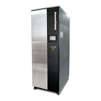
Modulating Boiler/Water Heater, 1,600/1,999/2,499/3,000/3,500/4,000 MBTU/h
Brand:
Laars
| Category:
Boiler
| Size: 15.19 MB
Table of Contents
Table of Contents
2
SECTION 1 General Information
5
A Introduction
5
B Warranty
5
Model Identification
5
D Safety Notes
6
E Unit Overviews
8
Dimensions
11
G Unpacking and the Installation Kit
12
SECTION 2 Locating the Unit
13
A Locating the Unit
13
B Correct Vent Distance from Outside Wall or Roof Termination
13
SECTION 3 Venting and Combustion Air
15
A General Venting
15
B Combustion Air
16
C Combustion Air from Room
16
Ducted Combustion Air
17
D Venting
17
Common Venting
18
Venting Requirements Unique to Canada
18
E Locating the Vent & Comb Air Terminals
19
Side Wall Vent Terminal
19
Side Wall Combustion Air Terminal
21
Vertical Vent Terminal
21
Vertical Combustion Air Terminal
21
Installations in the Commonwealth of Massachusetts
21
Common Vent Test
22
G Outdoor Installation
23
SECTION 4 Gas Supply and Piping 4.A Gas Supply and Piping
24
SECTION 5 Water Flow Requirements
26
Boiler Flow and Head Requirements
26
Water Heater Flow and Head Requirements
27
SECTION 6 Water Connection Boilers
28
A System Piping
28
Hot Supply Connections
28
Cold Water Make-Up
28
Freeze Protection
28
D Condensate Drain Trap
29
E Suggested Piping Schematics
29
SECTION 7 Water Connections
34
A Water Quality
34
B Suggested Piping Schematics
34
C Piping Requirements
34
E Water Flow
36
D Condensate Drain Trap
36
SECTION 8 Electrical Connections 8.A Installation Warnings
37
Main Power Connections
37
C Pump Connections and Operation
38
D Field Wiring
39
E Field Connections for Single Unit Installs
40
F Field Connections for Lead / Lag Installs
40
G Control Panel Layout
41
H Building Automation System Connections
42
I Lead Lag Connections
43
J Wiring Diagrams
44
K High Voltage Wiring Diagrams
48
L Ladder Diagrams
55
SECTION 9 Navigating the Touchscreen
62
A the Touch Screen
62
B Using the Touch Screen
62
C Screen Menu Icons
63
D Verification Process for Safety Related Parameters
64
E Checking Individual Parameters
65
F Configuring Parameters
66
G Setting the Date and Time
67
H Configuration Menus
68
System Identification & Access
68
CH - Central Heat Configuration
68
Outdoor Reset Configuration
68
DHW - Domestic Hot Water Configuration
69
Warm Weather Shutdown Configuration
69
Demand Priority Configuration
69
Modulation Configuration
69
Pump Configuration
70
Statistics Configuration
70
High Limits
70
Stack Limits
70
Delta T Limits
71
Frost Protection
71
Burner Control Ignition
71
System Configuration
71
Sensor Configuration
71
Lag (Slave) Configuration
72
Lead (Master) Configuration
75
I Parameter Defaults and Ranges
75
J C Onfiguring for a Gateway Control for BAS
79
KVARI-PRIME Flow Control System
80
L Combustion Setup Procedure
81
SECTION 10 Initial Startup Instructions
84
A Filling the Boiler System
84
B Initial Operation
85
Initial Burner Operation
85
Combustion Setup Procedure
85
C Shutting down the Unit
85
D Restarting the Unit
85
SECTION 11 Maintenance
86
A System Maintenance
86
B Maintenance Notes
86
Burner
86
Modulating Gas Valve/ Venturi
86
Controller
87
Spark Ignition Electrodes
87
11.2.5 Flame Sensor
87
Blower 1600
87
Blower 2000-4000
87
Heat Exchanger Tubes
88
Gas Pressure Switches
88
Battery Back up for Date and Time
89
SECTION 12 Troubleshooting
90
A Lockouts, Holds, and Alerts
90
Responding to a Lockout, Hold, or Alert
90
Iewing The Lockout And Alert Histories
90
B Troubleshooting Table
92
C Diagnostic Tests and Input/Output Indicators
101
D Lead Lag Diagnostics
102
E Statistics
102
F Analysis
102
G Control Snapshot
103
H Operating Sequence
103
SECTION 13 Replacement Parts
104
A General Information
104
B Component Illustrations, Parts Lists, and Part Numbers
105
F Rame And Jacket Assy, Part Numbers
105
Final Assembly, Part Numbers
107
Control Panel Assembly, Part Numbers
108
Blower Burner Assembly, Part Numbers (Model 1600)
109
Blower Burner Assembly, Part Numbers (Model 2000)
110
Blower Burner Assembly, Part Numbers (Models 2500 and 3000)
111
Blower Burner Assembly, Part Numbers (Models 3500 and 4000)
112
AC Distribution Box Assemblies and Part Numbers (Model 1600)
113
AC Distribution Box Assembly and Blower Part Numbers (Model 2000)
114
Part Numbers (Models 2500 To 4000)
115
Gas Train Assembly, Part Numbers (Models 1600, 2000, 2500 and 3000)
116
Gas Train Assembly, Part Numbers (Models 3500 and 4000)
118
Waterway Outlet Assembly, Part Numbers
120
Advertisement
Laars MAGNATHERM MGV4000 Installation And Operation Instructions Manual (116 pages)
Modulating Boiler & Water Heater
Brand:
Laars
| Category:
Boiler
| Size: 10.21 MB
Table of Contents
Table of Contents
2
Section 1 - GENERAL INFORMATION
5
Introduction
5
Safety Notes
5
Model Nomenclature / Identification
6
Warranty
6
Unit Overviews ( All Sizes )
7
Dimensions
10
Unpacking
11
Section 2 - LOCATING the APPLIANCE
11
Locating the Appliance
11
Correct Vent Distance from Outside Wall or Roof Termination
11
Section 3 - VENTING and COMBUSTION AIR
12
Combustion Air
12
Combustion Air from Room
12
Ducted Combustion Air
13
Venting
13
Common Venting
14
Venting Requirements Unique to Canada
14
Locating the Vent and Combustion Air Terminals
15
Side Wall Vent Terminal
15
Side Wall Combustion Air Terminal
17
Vertical Vent Terminal
18
Vertical Combustion Air Terminal
18
Installations in the Commonwealth of Massachusetts
18
Common Vent Test
19
Outdoor Installation
20
Section 4 - GAS SUPPLY and PIPING
20
Gas Supply and Piping
20
Section 5 - WATER FLOW REQUIREMENTS
22
Magnatherm Boiler Flow and Head Requirements
22
Magnatherm Water Heater Flow and Head Requirements
22
Section 6 - WATER CONNECTIONS, MGH
23
MGH System Piping: Hot Supply Connections
23
MGH Cold Water Make-Up
23
MGH Freeze Protection
23
MGH Suggested Piping Schematics
24
Condensate Drain Trap
24
Section 7 - WATER CONNECTIONS, MGV
29
MGV Water Quality
29
MGV Suggested Piping Schematics
29
MGV Piping Requirements
29
MGV Cold Water Make-Up
30
MGV Freeze Protection
30
MGV Water Flow
31
Condensate Drain Trap
31
Section 8 - ELECTRICAL CONNECTIONS
32
Installation Warnings
32
Main Power Connections
32
Pump Connections and Operation
33
Control Panel Layout
34
Wiring Diagrams
36
High Voltage Wiring Diagrams
40
Ladder Diagrams
45
Section 9 - NAVIGATING the TOUCH SCREEN
50
The Touch Screen
50
Using the Touch Screen
50
Verification Process for Safety-Related Parameters
52
Parameters
54
Configuring Parameters on Individual
54
Controllers
54
Setting the Date and Time on the System Display
55
Configuration Menus (All)
56
System Identification & Access
56
CH - Central Heat Configuration
57
Outdoor Reset Configuration
57
DHW - Domestic Hot Water Configuration
57
Warm Weather Shutdown Configuration
57
Demand Priority Configuration
57
Modulation Configuration
57
Pump Configuration
57
Statistics Configuration
58
High Limits
58
Stack Limits
58
Delta T Limits
58
Frost Protection Configuration
58
Burner Control Ignition
59
System Configuration
59
Sensor Configuration
59
Lead Lag Slave Configuration
60
Lead Lag Master Configuration
63
Parameter Defaults and Ranges
63
Connections to a Building Automation System
67
Vari-Prime Flow Control System
68
Combustion Setup Procedure
69
Section 10 - INITIAL STARTUP INSTRUCTIONS
72
Filling the Boiler System
72
Initial Operation
73
Initial Burner Operation
73
Combustion Setup Procedure
73
Shutting down the Magnatherm
73
Restarting the Magnatherm
73
Section 11 - MAINTENANCE
74
System Maintenance
74
Maintenance Notes
74
Burner
74
Modulating Gas Valve/ Venturi
74
Controller
75
Hot Surface Ignitor
75
Flame Sensor
75
Blower
75
Heat Exchanger Tubes
76
Gas Pressure Switches
76
Section 12 - TROUBLESHOOTING
77
About Lockouts, Holds, and Alerts
77
Responding to a Lockout, Hold, or Alert
77
Viewing the Lockout and Alert Histories
77
Troubleshooting Table
79
Diagnostic Tests and Input/Output Indicators
93
Lead/Lag Slave Diagnostics
94
Statistics
94
Analysis
94
Control Snapshot
95
Operating Sequence
95
Section 13 - REPLACEMENT PARTS
96
General Information
96
Component Illustrations, Parts Lists, and Part Numbers
97
Frame and Jacket Assembly
97
Final Assembly
99
Waterway Outlet Assembly
100
Blower Assy, Model 1600
101
Blower Assy, Model 2000
102
Blower Assy, Models 3500 & 3000
103
Blower Assy, Models 3500 & 4000
105
Gas Train Assembly, Models 1600 Thru 3000
107
Gas Train Assembly, Models 3500 & 4000
108
Control Panel Assembly
111
Distribution Box Assemblies
112
Laars MAGNATHERM MGV4000 Installation And Operation Instructions For (104 pages)
Modulating Boiler Water Heater
Brand:
Laars
| Category:
Boiler
| Size: 9.36 MB
Table of Contents
Table of Contents
2
Section 1 - General Information
5
Introduction
5
Safety Notes
5
Model Identification
6
Warranty
6
Unit Overviews 2MBH, 3MBH, 4MBH
7
Dimensions
10
Section 2 - LOCATING the APPLIANCE
11
Unpacking
11
Locating the Appliance
11
Correct Vent Distance from Outside Wall or Roof Termination
11
Section 3 - Venting and Combustion Air
12
Combustion Air
12
Combustion Air from Room
12
Ducted Combustion Air
13
Venting
13
Common Venting
14
Venting Requirements Unique to Canada
14
Locating the Vent and Combustion Air Terminals
15
Side Wall Vent Terminal
15
Side Wall Combustion Air Terminal
17
Vertical Vent Terminal
18
Vertical Combustion Air Terminal
18
Installations in the Commonwealth of Massachusetts
18
Common Vent Test
19
Outdoor Installation
20
Section 4 - Gas Supply and Piping
20
Gas Supply and Piping
20
Section 5 - PUMP REQUIREMENTS
22
Magnatherm Boiler Flow and Head Requirements
22
Magnatherm Water Heater Flow and Head Requirements
22
Section 6 - WATER CONNECTIONS, MGH
23
MGH System Piping: Hot Supply Connections
23
MGH Cold Water Make-Up
23
MGH Freeze Protection
23
MGH Suggested Piping Schematics
24
Condensate Drain Trap
24
Section 7 - WATER CONNECTIONS, MGV
29
MGV Water Quality
29
MGV Piping Requirements
29
MGV Suggested Piping Schematics
30
MGV Cold Water Make-Up
30
MGV Freeze Protection
30
MGV Water Flow
31
Condensate Drain Trap
31
Section 8 - Electrical Connections
32
Installation Warnings
32
Main Power Connections
32
Pump Connections and Operation
33
Control Panel Layout
34
Wiring Diagram
36
High Voltage Wiring Diagrams
38
Ladder Diagrams
41
Section 9 - Navigating the Touch Screen
44
The Touch Screen
44
Using the Touch Screen
44
Verification Process for Safety-Related Parameters
46
Parameters
46
Configuring Parameters on Individual
48
Setting the Date and Time on the System Display
49
Configuration Menus (All)
50
System Identification & Access
50
CH - Central Heat Configuration
51
Outdoor Reset Configuration
51
DHW - Domestic Hot Water Configuration
51
Warm Weather Shutdown Configuration
51
Demand Priority Configuration
51
Modulation Configuration
51
Pump Configuration
51
Statistics Configuration
52
High Limits
52
Stack Limits
52
Delta T Limits
52
Frost Protection Configuration
52
Burner Control Ignition
53
System Configuration
53
Sensor Configuration
53
Lead Lag Slave Configuration
54
Lead Lag Master Configuration
57
Parameter Defaults and Ranges
57
Connections to a Building Automation System
61
Vari-Prime Flow Control System
62
Combustion Setup Procedure
63
Section 10 - Initial Startup Instructions
66
Filling the Boiler System
66
Initial Operation
67
Initial Burner Operation
67
Combustion Setup Procedure
67
Shutting down the Magnatherm
67
Restarting the Magnatherm
67
Section 11 - Maintenance
68
System Maintenance
68
Maintenance Notes
68
Burner
68
Modulating Gas Valve/ Venturi
68
Controllers
69
Hot Surface Ignitor
69
Flame Sensor
69
Blower
69
Heat Exchanger Tubes
69
Gas Pressure Switches (Optional)
70
Natural/Propane Gas Conversion
70
Section 12 - Troubleshooting
71
About Lockouts, Holds, and Alerts
71
Responding to a Lockout, Hold, or Alert
71
Viewing the Lockout and Alert Histories
71
Troubleshooting Table
73
Diagnostic Tests and Input/Output Indicators
87
Lead/Lag Slave Diagnostics
88
Statistics
88
Analysis
88
Control Snapshot
89
Operating Sequence
89
Section 13 - Replacement Parts
90
General Information
90
Component Illustrations, Parts Lists, and Part Numbers
91
Frame and Jacket Assembly
91
Final Assembly
93
Waterway Outlet Assembly
94
Burner Assembly, Model 2000
95
Burner Assembly, Model 3000
96
Burner Assembly, Model 4000
97
Gas Train Assembly, Models 2000 & 3000
99
Gas Train Assembly, Model 4000
101
Control Panel Assembly
103
Advertisement
Related Products
Laars MAGNATHERM MGV2000
Laars MAGNATHERM MGV3000
Laars MagnaTherm MGV1600
Laars MagnaTherm MGV2500
Laars MagnaTherm MGV3500
Laars MAGNATHERM MGH3000
Laars MAGNATHERM MGH2000
Laars MAGNATHERM MGH4000
Laars MagnaTherm MGH1600
Laars MagnaTherm MGH2500
Laars Categories
Boiler
Water Heater
Swimming Pool Heater
Industrial Equipment
Heater
More Laars Manuals
Login
Sign In
OR
Sign in with Facebook
Sign in with Google
Upload manual
Upload from disk
Upload from URL