Sign In
Upload
Manuals
Brands
Kustom Signals Manuals
Car Video System
Digital Eyewitness HD
Kustom Signals Digital Eyewitness HD Manuals
Manuals and User Guides for Kustom Signals Digital Eyewitness HD. We have
1
Kustom Signals Digital Eyewitness HD manual available for free PDF download: Installation Manual
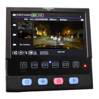
Kustom Signals Digital Eyewitness HD Installation Manual (70 pages)
Brand:
Kustom Signals
| Category:
Car Video System
| Size: 6.19 MB
Table of Contents
Table of Contents
5
1 Product Description
9
General Description
9
Basic Digital Eyewitness ® HD System
9
Optional Eyewitness ® HD System Components
10
Checking the Order
11
Figure 1-1. Example Top Tray
11
Figure 1-2. Example Middle Tray
11
Figure 1-3. Example Bottom Tray
11
Installer Qualifications
12
Order of Installation
12
Protecting against RFI (Radio Frequency Interference)
13
Power/Ground Connection Requirements
14
Eyewitness ® HD System Serial Numbers
14
Figure 1-4. Serial Number Location on the DVR
14
Figure 1-5. HD Camera Serial Number Label
15
Figure 1-6. Monitor Serial Number Label
15
Figure 1-7. Rear Seat Camera Serial Number Label
15
Figure 1-8. Expanse Transmitter Base Serial Number Label
16
Figure 1-9. Expanse Transmitter Serial Number Label
16
2 Installing the Tablet Monitor Controller (TMC)
17
General Description
17
Preparing the Tablet Monitor Controller (TMC) for the Ball and Socket Mount Installation
17
Figure 2-1. Tablet Monitor Controller
17
Figure 2-2. Ball Stud Installed in Display Mounting Plate
18
Figure 2-3. Tablet Monitor Controller Cable Connection and Cable Routing
19
Figure 2-4. Align the Display Mounting Plate with the Holes in the Display
19
Tablet Monitor Controller Installation
20
TMC Ball and Socket Mount
20
Figure 2-5. Ferrite Clamp Installation on Tablet Monitor Control Cable
20
Figure 2-6. Display Mount Base
21
Figure 2-7. Dual Ball Mount Receiver
21
Headliner Mount
22
Figure 2-8. Overhead Console Removed
22
Figure 2-9. Headliner Cutout
22
Figure 2-10. Creating the Hole for the Center Nut
23
Figure 2-11. Wire Routing through Headliner
23
Figure 2-12. Preparing the Fastener for the Center Nut
24
Figure 2-13. Final Mounting Position
24
3 Installing the Cameras and In-Car Microphone (ICM)
25
General Description
25
Installing an HD Camera with Standard Combination Camera/Expanse Audio Transmitter Base Mount (Part # 050-0695-04)
25
Figure 3-1. Brace (Top View)
25
Figure 3-2. Antenna Cable Connection at Expanse Transmitter Base
26
Figure 3-3. Expanse Transmitter Antenna
26
Figure 3-4. Route the Camera and Audio Transmitter Base Cables
26
Figure 3-5. Installing the Sun Visor Clip over the Mounting Bracket
27
Figure 3-6. Proper Final Position of Antenna
28
Figure 3-7. Camera Mounting Hardware
28
Initial Checks Prior to Installing Camera on Windshield or Headliner Mounting Tab
28
Installing an HD Camera with Windshield Mount (Part # 050-0615-00)
29
(Part # 050-0615-00)
29
Figure 3-8. Windshield Mounting Tab
30
Figure 3-9. Proper Orientation of the Windshield Mounting Tab
30
Figure 3-10. Jam Nuts Properly Installed
31
Figure 3-11. Top of HD Camera
32
Figure 3-12. HD Camera on Windshield Mount
32
Figure 3-13. Jam Nuts Properly Installed
33
Figure 3-14. Camera Bracket on Top of Camera
34
Figure 3-15. Headliner Mounting Tab
34
Installing the In-Car Microphone
35
Figure 3-16. In-Car Microphone Mounting
35
Installing the Rear Seat Camera with Integrated In-Car Microphone
36
Figure 3-17. Inline Camera Connection
36
Figure 3-18. Inline Camera Connection Secured with Electrical Tape
37
4 Routing and Installing System Cables
39
General Description
39
Basic Cabling Information
39
Side Airbag Precautions
40
Radio Frequency Interference (RFI) Prevention
40
Routing Cables through Bulkheads
40
Managing Excess Cable
41
Figure 4-2. Power Cable Routed through Factory Pass-Thru
41
Figure 4-3. Managing Cables - Creating a Dog Bone
41
Mini-Octopus (Mini-OTP) Cable (Part # 155-3952-00)
42
Figure 4-4. OTP Cable
42
Figure 4-5. OTP Cable Connection at the DVR
42
Accessory Cable (Part # 155-3956-25)
43
Figure 4-6. Wire Color and Uses
43
Installing the Power Cable (Part # 155-3957-25)
45
Figure 4-7. Power Cable Taped to Fish Tape
45
Installing the Power Tamer
46
Figure 4-8. Sample Power Tamer Mounting Location (Inner Fender - Crown VIC)
46
Figure 4-9. Chassis Ground Connection (Charger Shown)
47
5 Installation of GPS and Wi-Fi Antennas
49
General Information
49
Installing GPS Components (Part # 015-1599-00)
49
Figure 5-1. GPS Antenna - Example A-Pillar Mount
49
Installing Wireless N File Transfer 5.0 Ghz Antenna Components
50
(Part # 050-0860-00)
50
Figure 5-2. Wi-Fi Antenna Mounting Screws
50
Figure 5-3. Completed Antenna Installation
51
Figure 5-4. Wireless Antenna Connections on Rear of DVR
51
6 Installation of the Digital Video Recorder (DVR)
53
General Description
53
DVR Front Panel
53
Figure 6-1. Front Panel of the DVR
53
DVR Rear Panel
54
Figure 6-2. Rear View of DVR
54
DVR Heat Management
55
Figure 6-3. DVR Vent Holes
55
Figure 6-4. DVR Heat Sink
55
DVR / System Serial Number Locations
56
Preparing the DVR for Mounting
56
Mounting the DVR
56
Figure 6-5. Cage Mounted DVR on Back of Rear Cage - SUV Installation
56
Figure 6-6. Floor Mounted Location of DVR
57
Figure 6-7. GPS Antenna Connection
57
Figure 6-8. Wireless File Transfer Antenna Connections
58
Figure 6-9. Mini-OTP Cable Connections
58
Figure 6-10. Tablet Monitor Controller (TMC) Connection
58
Figure 6-11. MDC Control Connection
58
Figure 6-12. Camera Connections
59
Figure 6-13. Accessory Cable Connection
59
7 Installation of the Mobile Data Computer (MDC) Option
61
General Description
61
Minimum System Requirements
61
Eyewitness ® HD MDC Installation Instructions
61
Figure 7-1. Determine Which Port the Ethernet Cable Is Connected to
62
Figure 7-2. Local Area Connection Properties
62
Figure 7-3. Internet Protocol Version 4 (Tcp/Ipv4) Properties
63
Figure 7-4. Preinitsettings.json File in Text Editor
63
Figure 7-5. MDC Controller
64
8 Field Verification of File Transfer Operability
65
General Information
65
Figure 8-1. Wi-Fi Signal Strength Indicator
65
Figure 8-2. Example Starting File Transfer Session Message
65
Figure 8-3. Example File Transfer Messages
66
Figure 8-4. Example File Transfer Finished Message
66
Figure 8-5. Example File Transfer Failed Message
66
Index
69
Advertisement
Advertisement
Related Products
Kustom Signals EAGLE II
Kustom Signals Eagle 3
Kustom Signals Eyewitness G3
Kustom Signals Categories
Radar
Controller
Car Video System
Measuring Instruments
Industrial Monitor
More Kustom Signals Manuals
Login
Sign In
OR
Sign in with Facebook
Sign in with Google
Upload manual
Upload from disk
Upload from URL