Sign In
Upload
Manuals
Brands
Kurz Manuals
Measuring Instruments
454FTB
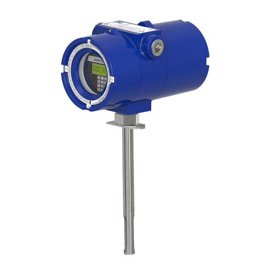
Kurz 454FTB Thermal Mass Flowmeter Manuals
Manuals and User Guides for Kurz 454FTB Thermal Mass Flowmeter. We have
3
Kurz 454FTB Thermal Mass Flowmeter manuals available for free PDF download: Hardware Manual, Startup Manual
Kurz 454FTB Hardware Manual (162 pages)
B-Series
Brand:
Kurz
| Category:
Measuring Instruments
| Size: 6 MB
Table of Contents
Table of Contents
3
List of Tables
9
List of Figures
11
Preface
13
Before You Begin
14
Using this Manual
14
Manual Conventions
14
Introduction
15
Overview
15
Specifications & Features
16
Process Specifications & Conditions
16
Support & Element Components
17
Transmitter Features
18
Approvals & Compliance
19
Flow Meter Options
19
Communications Requirements
20
Hardware Requirements
20
Software Requirements
20
Configuration Checklist
21
Quick Reference Card
22
Figure 1-1. User Interface Quick Reference Card
22
Installation
23
Overview
23
Mounting & Sensor Placement
24
Figure 2-1. Probe Support and Sensors
24
Figure 2-2. Mounting and Sensor Criteria for the 454FTB
25
Figure 2-3. Mounting and Sensor Criteria for the 454FTB-WGF
25
Figure 2-4. Probe Sensor Placement (Installation Angle) for Wet Gas
26
Hardware Description
28
Figure 2-5. Location of 454FTB Components
28
Display/Keypad Orientation
29
Electronics Head Orientation
29
Figure 2-6. Flow Arrow
29
Flow Arrow
29
Figure 2-7. Display/Keypad Rotation (with Cover Removed)
30
Mounting Transmitter-Separate (TS) Models
30
Figure 2-8. TS Electronics with Covers Removed
31
Figure 2-9. Examples of Unistrut and Pipe Mounting Using the Optional
31
Field Wiring
32
Safety Grounding and Explosion Proof Connections
32
Water Protection
33
24 VDC Powered Flow Transmitters
34
AC/DC Power Requirements & Connections
34
AC Powered Units
35
Figure 2-10. AC/DC Power Connection
35
Figure 2-11. AC Power Pull Tab
35
K-BAR System Installation
36
Figure 2-12. Typical K-BAR 2000B Installation Configurations
37
Mounting
37
Figure 2-13. K-BAR 2000B Electronics Configuration Examples
38
K-BAR Electronics Configurations
38
Figure 2-14. K-BAR 2000B Transmitter-Attached Electronics Example
39
Figure 2-15. K-BAR 2000B Transmitter-Separate Electronics Example
40
K-BAR Purge Option
41
Figure 2-16. K-BAR 2000BP Multipoint Controller Circuit Board Example
42
Purge Interval Settings
43
Purge Recovery Settings
43
Acknowledgement Output Signal
44
Purge Bar Settings
44
Remote Purge
44
Analog Output Configuration & Wiring
45
AO Capabilities
45
Hart
45
Loop Powered Wiring
45
NE-43 Alarm
45
Self-Powered Wiring
45
Clip-On Ferrite for Signal Wires
46
Alarms
46
Figure 2-17. Clip-On Ferrite for I/O Wires
46
Serial Communications
47
Usb
47
Figure 2-18. K-BAR Example Using Modbus Communication
48
RS-485/Modbus
48
Figure 2-19. Flex Sensor Connection for Service Loop, TA Version Using Liquid
49
Figure 2-20. Cable and Lines Applicable to EMC Shielding of 5-Wire Sensor
49
Flex Wiring Connection for Sensor Inspections
49
5-Wire Sensor Connections
50
Figure 2-21. Cable Gland Example with Braided Shielded Cable
50
Overview
53
Remote Terminal & Data Logging
54
Figure 3-1. B-Series USB Connector
54
Setting up Remote Terminal Communications
54
Modbus
56
Identifying the COM Port
56
Configuring a Terminal Emulator
57
Figure 3-2. Tera Term Serial Port Setup
57
B-Series ASCII Commands
58
Disconnecting a Terminal Emulator
58
Upload and Download Commands
59
Downloading or Updating a Configuration File
60
Uploading or Backing up a Configuration File
60
Setting Flow Meter Modbus Connectivity
61
Modbus Commands and Registers
63
Kurz Floating Point Data Formats
67
Modbus ASCII Compatibility Issues
67
Modbus Biasing
67
Figure 3-3. Modbus Multipoint Serial Connections
68
Figure 3-4. Half-Duplex Modbus Serial Communications on an RS-485 Bus
68
Troubleshooting
71
Overview
71
Data Logging & Reporting
72
USB Port Data Logging
72
USB Port ASCII Commands
73
Built-In Diagnostics
73
Event Code Log
74
Diagnostic Error Limits
79
Internal Volatile RAM Data Logging
79
Modbus Registers
80
Single-Wire Fault Codes
80
Typical Symptoms of a Damaged Display
80
Advanced Diagnostics Menus
81
Returning Equipment
83
Cleaning Equipment before It Is Returned
84
Receiving an RMA Number
84
Shipping Equipment
84
AppendixA Drawings & Diagrams
85
Overview
85
454FTB Outline Drawing (1 of 2)
86
454FTB Outline Drawing (2 of 2)
87
454FTB-WGF Outline Drawing (1 of 2)
88
454FTB-WGF Outline Drawing (2 of 2)
89
504FTB Outline Drawing (1 of 2)
90
504FTB Outline Drawing (2 of 2)
91
Field Wiring Diagram (1 of 6) - Component Diagram
92
Field Wiring Diagram (3 of 6) - Alarms & Purge Connections
94
Field Wiring Diagram (4 of 6) - Modbus Connections
95
Field Wiring Diagram (5 of 6) — Notes
95
Field Wiring Diagram (5 of 6) - Notes
96
Field Wiring Diagram (6 of 6) - Notes
97
Field Wiring Diagram (1 of 2) - TS Configuration
98
Field Wiring Diagram (2 of 2) - TS Configuration Notes
99
AO Self-Powered Outputs (1 of 1)
100
Field Wiring Diagram (1 of 6) - Fiberglass Wall Mount Component Diagram
101
Field Wiring Diagram (2 of 6) - Fiberglass Wall Mount 4-20Ma Connections
102
Field Wiring Diagram (3 of 6) - Fiberglass Wall Mount Alarms & Purge Components
103
Field Wiring Diagram (4 of 6) - Fiberglass Wall Mount Modbus Connections
104
Field Wiring Diagram (5 of 6) - Fiberglass Wall Mount Notes
105
Field Wiring Diagram (6 of 6) - Fiberglass Wall Mount Notes
106
K-BAR 2000B Wiring Diagram (1 of 4)
107
K-BAR 2000B Wiring Diagram (2 of 4)
108
K-BAR 2000B Wiring Diagram (3 of 4)
109
K-BAR 2000B Wiring Diagram (4 of 4)
110
Isokinetic Systems (1 of 2)
111
Isokinetic Systems (2 of 2)
112
AppendixB
113
Overview
113
Certifications, Approvals, and Compliance
114
Safety Labels
119
ATEX Standards
120
DC Power, Ex Na (Non-Incendive) Label
120
Figure B-1. Ex Na Safety Label for DC Power
120
AC Power, Ex Na (Non-Incendive) Label
121
Ex Na Application Graphs
121
Figure B-2. Ex Na Safety Label for AC Power
121
Figure B-3. Ex Na Application, Sensor AIT Vs. Process Temperature
121
DC Power, Ex D Label
122
Figure B-4. Ex Na Application, Electronics Enclosure AIT Vs
122
Figure B-5. Ex D Safety Label for DC Power
122
AC Power, Ex D Label
123
Ex D Application Graphs
123
Figure B-6. Ex D Safety Label for AC Power
123
Figure B-7. Ex D Application, Sensor AIT Vs. Process Temperature
123
Figure B-8. Ex D Application, Electronics Enclosure AIT Vs
124
EC Declaration of Conformity - B-Series
125
ATEX Ex N
125
ATEX Ex D
126
Ped
127
Ped
128
Emc
129
Lvd
129
Rohs
129
Weee
129
AppendixC Zero Flow Calibration
131
Overview
131
Figure C-1. Zero Flow Calibration Chamber
132
Performing a Zero Flow Calibration Test
132
Figure C-2. Flow Meter Position for Zero Flow Calibration Test
133
Zero Flow Assembly Parts
135
Figure C-4. Zero Flow Calibration Chamber - Exploded View
136
AppendixD Calibration
137
Overview
137
Raw Velocity
138
Velocity Traverse Data Acquisition
138
Velocity Traverse Reference Method
139
Equal Areas for a Rectangular Duct
139
Figure D-1. Example of Rectangular Duct Cross-Section Perpendicular to Flow
140
Equal Areas for a Circular Duct
141
Figure D-2. Example of Circular Duct Cross-Section Perpendicular to Flow
142
Traverse Probe Blockage
144
Series 2440 Configuration
146
Configuring Internal Memory Log
146
Storing Data in Test Memory
148
Viewing the Data Stored in the Test Memory
149
Velocity Probe & the Pitot Tube
151
Advertisement
Kurz 454FTB Startup Manual (26 pages)
MFT B-Series Firmware 2.x
Brand:
Kurz
| Category:
Measuring Instruments
| Size: 0 MB
Table of Contents
Unpacking/Expected Content
2
Mounting of the Equipment (See Guidelines Sheet)
2
Basic Setup
10
Remote Display Setup
10
Wiring, Sensor, Power and Signals
11
Analog Output
12
Display Orientation
13
Navigating Menus
13
Meter Programming
14
Meter Programming with the USB Port
21
Field Calibration
23
Output Setup
23
Serial Output
23
Kurz 454FTB Startup Manual (22 pages)
Brand:
Kurz
| Category:
Measuring Instruments
| Size: 0 MB
Table of Contents
Unpacking/Expected Content
2
Mounting of the Equipment (See Guidelines Sheet)
2
Basic Setup
9
Remote Display Setup
9
Wiring, Sensor, Power and Signals
10
Analog Output
11
Display Orientation
12
Navigating Menus
12
Insertion Meter Programming
13
Field Calibration
16
Tag/Labeling of the Meter
16
Output Setup
19
Analog Output Range
19
Serial Output
20
Advertisement
Advertisement
Related Products
Kurz 490 series
Kurz 410FTB
Kurz 452 Series
Kurz 452T
Kurz 452P
Kurz 452PT
Kurz 155
Kurz 504FTB
Kurz 534FTB
Kurz B-Series
Kurz Categories
Measuring Instruments
Transmitter
More Kurz Manuals
Login
Sign In
OR
Sign in with Facebook
Sign in with Google
Upload manual
Upload from disk
Upload from URL