Sign In
Upload
Manuals
Brands
Krone Manuals
Farm Equipment
Big Pack 4x4 XC
User Manuals: Krone Big Pack 4x4 XC Large Square Baler
Manuals and User Guides for Krone Big Pack 4x4 XC Large Square Baler. We have
1
Krone Big Pack 4x4 XC Large Square Baler manual available for free PDF download: Operator's Manual
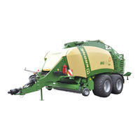
Krone Big Pack 4x4 XC Operator's Manual (332 pages)
Baler
Brand:
Krone
| Category:
Farm Equipment
| Size: 22 MB
Table of Contents
Foreword
3
Table of Contents
4
Introduction
12
Purpose of Use
12
Validity
12
Contact
12
Identification Plate
13
Information Required for Questions and Orders
13
Intended Use
14
Technical Data
15
Lubricants
16
Filling Quantities and Lubrication Designations for Gearboxes
16
Oil Quantities and Designations for the On-Board Hydraulic System
17
Oil Quantities and Designations for the Compressor
17
General Technical Description
18
Connection Prerequisites on Tractor
19
Electrical Connections
19
Hydraulic Connections
20
Machine Overview
22
Left Side of the Big Pack Baler with Tandem Axle
22
Right Side of the Big Pack Square Baler with Tandem Axle
24
How the VFS Conveyor System Works
26
Functional Description of the Big Pack Baler
27
Safety
28
Identifying Symbols in the Operating Instructions
28
Identification of the Hazard Warnings
28
Personnel Qualification and Training
29
Dangers in Case of Non-Compliance with the Safety Instructions
29
Safety-Conscious Work Practices
29
Safety Instructions and Accident Prevention Regulations
30
Hitched Implements
31
PTO Operation
32
Hydraulic System
33
Tyres
33
Maintenance
34
Unauthorised Conversion/Modification and Spare Parts Production
34
Inadmissible Modes of Operation
34
Safety Instructions on the Machine
34
Introduction
35
Position of the Adhesive Safety Stickers on the Machine
36
Position of the General Information Labels on the Machine
38
Re-Ordering the Adhesive Safety and Information Labels
39
Affixing the Adhesive Safety and Information Labels
39
Special Safety Instructions
40
Ladder
40
Safety Railing
42
Fire Extinguisher
43
Wheel Chocks
43
Parking Brake
44
Flywheel Brake
45
Parking Support
46
Hydraulic Parking Jack (Optional)
47
Commissioning
49
Adjusting the Drawbar Height
50
Adjusting the Height of the Drive Train
52
Mounting Onto the Tractor
53
PTO Shaft
54
Length Adjustment
54
KRONE ISOBUS-Terminal CCI 100
56
Installing the Terminal into Cabin
57
ISOBUS Short Cut Button
58
Connecting the Terminal (on Tractors with Integrated ISOBUS System)
60
Connecting the Terminal (on Tractors Without ISOBUS System)
61
Connecting the Multi-Function Lever to the CCI Terminal (on Tractors Without ISOBUS System)
62
Switching the Terminal on / off When the Machine Is Not Connected
63
Switching the Terminal on / off When the Machine Is Connected
64
Function Keys
66
Manual Mode
72
Manual Mode Basic Screen
72
Setting the Target Bale Channel Flap Pressure
75
Setting the Bale Length
76
Automatic Mode
78
Buttons on the Machine
80
Description of Baling Process
81
Bale Channel Chamber Empty
81
Bale Channel Chamber Full
81
Menu Level
82
Short Overview
82
Calling up the Menu Level
83
Main Menu 1 „Settings
84
Menu 1-1 „Knotter Settings
85
Menu 1-1-1 „Correction Value for Bale Length
86
Menu 1-1-2 „Knotter Signal
87
Menu 1-1-3 „Knotter Monitoring
88
Menu 1-1-5 „Bales / Blow
89
Menu 1-1-6 „Blow Time
90
Menu 1-2 Silage Agents / Optional
91
Menu 1-3 „Sensitivity of the Direction Display
92
Menu 1-4 „Central Lubrication
94
Menu 1-5 „Moisture Measuring
96
Menu 1-6 „Bale Balance
98
Adjusting the Bale Balance
99
Zeros
99
Main Menu 2 „Counters
101
Menu 2-1 „Customer Counter
102
Menu 2-1-1
104
Menu 2-2 „Total Bale Counter
106
Main Menu 4 "Service
108
Menu 4-2 „Manual Sensor Test
109
Actuator Test
117
Menu 4-4 Manual Actuator Test
117
Menu 4-6 „Diagnostics Driving Speed / Motion Direction Display
122
Menu 4-7 „Diagnostics Auxiliary (AUX)
123
Main Menu 5 'Information
124
Main Menu 6 „Fitter
125
Main Menu 9 "Virtual Terminal (VT)
126
Menu 9-2 „Switching between the Terminals
127
Menu 9-3 „Configuration Main Window
128
Alarm Message
130
Alarm Messages
131
ISOBUS Operation
138
Attaching the ISOBUS Terminal
139
Connection Terminal to Tractor
139
Connection Tractor to Machine
139
Differing Functions to KRONE ISOBUS Terminal CCI
140
Menu 4-6 "Diagnostics Driving Speed Display/Direction of Travel Display
141
Menu 4-7 "Diagnostics Auxiliary (AUX)
142
Main Menu 9 "ISO Settings Info
143
Menu 9-1 "Softkeys ISO Terminal
144
Menu 9-2 „Switching between the Terminals
145
ISOBUS „Auxiliary"-Function (AUX)
146
Example of a Joystick Assignment for Fendt (Default Setting)
147
Recommended Assignment of a WTK- Multi-Function Lever
148
Start-Up
149
Mounting Onto the Tractor
150
Install the PTO Shaft
151
Hydraulics
153
Special Safety Instructions
153
Connecting the Hydraulic Lines
153
Hydraulic Brake (Export)
156
Hydraulic Brake (Export France)
157
Hydraulic Connection to Block the Coaster/Steering Axle (Special Equipment)
158
Load-Sensing Connection
159
Operating the Machine Without LS (Load-Sensing Connection)
159
Operating the Machine Via LS (Load-Sensing Connection)
159
Compressed Air Connections for the Compressed Air Brake
160
Supports for Compressed Air Hoses
160
Using the Safety Chain
161
Electrical Connections
162
Working Floodlight
163
LED Strips
163
Driving and Transport
164
Preparations for Road Travel
164
Lifting the Pick-Up
164
Roller Chute Hydraulically Activated
165
Checking the Lighting System
166
Parking Brake
166
Moving
167
Handling the Coaster/Steering Axle (Special Equipment)
168
Moving the Machine Without Hydraulic Connections
170
Parking
171
Parking Brake
172
Wheel Chocks
173
Operation
174
Pick-Up
174
Cutting System
175
General
175
Cutting Length
176
Activating the Cutting System
177
Blade Changing
177
Unlocking the Blade Shaft
179
Removing Blockages
180
Baling Force Regulation
181
Ejection of the Last Bale
182
Opening the Bale Channel Chamber
182
Medium Design
182
Comfort Design
182
Activating the Bale Ejector
183
Medium Electronics Design
183
Comfort Electronics Design
183
Hydraulically Foldable Roller Chute
184
Medium Design
184
Comfort Version
184
Length Adjustment of Big Bales
184
Electrical Longitudinal Adjustment Device
184
Twine
185
Electrical Twine Empty Display
185
Twine Motion Indicator Upper Twine (Double Knotter)
186
Initiate the Tying Process Manually
187
Drives
188
Main Drive
188
Knotter Shaft Drive
189
Feed Packer Drum Drive
189
XC Cutting System Drive
190
Pick-Up Drive (for the XC Cutting System Version)
190
Pick-Up Drive Via Gearbox (Without Cutting System XC)
191
Bale Brake
191
Settings
192
Tying Unit
193
Inserting the Twine
193
Interconnecting the Twine (Twine Box)
194
Threading the Twine
195
Lower Twine Double Knotter
195
Upper Twine
196
Setting the Needles
197
Lateral Setting of the Needles
197
Setting the Height of the Needles on the Knotter
198
Top Dead Centre of the Needles
199
Adjusting the Needle Yoke Brake
200
Checking / Adjusting Position of Needles - Baling Ram
202
Setting the Upper Needle
203
Checking the Setting of the Upper Needle
203
Twine Bar
204
Setting the Twine Bar (Double Knotter)
204
Checking Twine Bar
205
Pretension of the Twine Bar Shaft
208
Setting the Knotter Shaft Brake
208
Twine Brake Fehler! Textmarke nicht Definiert
209
Setting the Twine Tension on the Upper Twine Strand (Double Knotter)
210
Setting the Twine Tension of the Lower Twine Strand (Double Knotter)
211
Knotter
212
Locking the Tying Process
212
Start-Up
213
Double Knotter
213
Knotter Hook (Double Knotter)
213
Setting of Twine Retainer
214
Setting the Holding Force of the Twine Retainer (6)
215
Setting the Blade Lever (Double Knotter)
216
Baling Ram Setting
218
Setting the Baling Ram Blades
218
Cleaning the Running Rails
219
Lateral Setting of the Plunger
219
Adjusting the Packer Relative to the Plunger
220
Description of Components
220
Checking Packer Coupling
222
Moving Packer Strip into Position
222
Moving Baling Ram into Position
223
Checking Feeder Strip Relative to the Baling Ram
224
Description of Components VFS System (Variable Filling System)
226
Presetting Threaded Rod / Stop for the Feeler Rocker
227
Zero Position (VFS System)
228
Adjusting the Spring of the Zeroizing Device
229
Adjusting the Triggering Sensitivity
230
Adjusting the Feeler Rocker
232
Adjusting the Feeler Rocker Stop
234
Absorbing Mechanism
235
Basic Setting of the Band Brake (Flywheel)
236
Setting the Bale Chute
236
Pick-Up
237
Default Setting (Working Height Setting)
237
Ground Pressure of the Guide Wheels
238
Driving with Pick-Up in Fixed Position
239
Roller Crop Guide
240
Maintenance
241
Special Safety Instructions
241
Test Run
241
Lifting
242
Lifting Eyes
242
Tightening Torques
243
Tightening Torques (Countersunk Screws)
244
Cleaning
245
Drive Chains
246
Conveyor Roller (I)
246
Pick-Up Drive (II)
246
Pick-Up Drive (III)
247
Tyres
248
Checking and Maintaining Tyres
248
Tyre Air Pressure
249
Hydraulics
250
On-Board Hydraulic System
251
High-Pressure Filter
252
Adjusting the Hydraulic System
253
Comfort Hydraulic Block Diagram
255
Emergency Manual Activation
256
Examples of Emergency Manual Activation
256
Raising / Lowering the Roller Chute
256
Pressing Force Control (with Emergency Manual Activation)
257
Setting the Baling Pressure
257
Releasing the Bale Channel Chamber (Comfort)
257
Filling Quantities and Lubrication Designations for Gearboxes
258
Oil Quantities and Designations for the On-Board Hydraulic System
258
Oil Quantities and Designations for the Compressor
258
Oil Level Check and Oil Change Intervals (Gearboxes)
258
Main Gearbox
259
Packer Gearbox
260
Transfer Gearbox
261
Pick-Up Gearbox
262
Cutting System Drive Gear
263
Maintenance - Brake System
265
Special Safety Instructions
265
Compressed-Air Reservoir
266
Setting the Transfer Mechanism
267
Pneumatic Brake Cylinders
268
Compressor
269
Maintenance - Lubrication
270
Special Safety Instructions
270
Lubricants
271
General Aspects
271
Lubricating the PTO Shaft
272
Lubricating the Rollers for the Blade Lever
272
Manual Lubrication Points on the Machine
273
Automatic Centralised Lubrication System (Optional)
277
Position of Sensors (Right-Hand Side of the Machine)
278
Position of Sensors (Left Side of Machine)
279
Adjusting the Sensors
281
Namur Sensor D = 12 MM
281
Namur Sensor D = 30 MM
281
Placing in Storage
282
Special Safety Instructions
282
At the End of the Harvest Season
283
Before the Start of the New Season
284
Overload Coupling on Flywheel
285
Malfunctions - Causes and Remedies
286
Special Safety Instructions
286
General Malfunctions
287
Malfunctions on the Knotter
290
Double Knotter
290
Troubleshooting in the Central Lubrication
301
Appendix
302
Hydraulic System Circuit Diagrams
302
On-Board Hydraulics for Medium Version Electronics
302
On-Board Hydraulics for Comfort Version Electronics
303
Working Hydraulics for Medium Version Electronics
304
Working Hydraulics for Comfort Version Electronics
305
Electrical Circuit Diagram
306
Index
306
Index
307
Advertisement
Advertisement
Related Products
Krone Swadro 46 T
Krone Swadro 46
Krone Swadro 42
Krone 4XL-RGL
Krone Swadro 42 T
Krone Big Pack 4x4
Krone Big Pack 890
Krone Big Pack 1290
Krone Big Pack 1270
Krone Big Pack 1290 HDP
Krone Categories
Farm Equipment
Lawn Mower
Lawn and Garden Equipment
Utility Vehicle
Industrial Equipment
More Krone Manuals
Login
Sign In
OR
Sign in with Facebook
Sign in with Google
Upload manual
Upload from disk
Upload from URL