Sign In
Upload
Manuals
Brands
Kollmorgen Seidel Manuals
Inverter
67WKS-M240/3-P0
User Manuals: Kollmorgen Seidel 67WKS-M240/3-P0 Drive
Manuals and User Guides for Kollmorgen Seidel 67WKS-M240/3-P0 Drive. We have
1
Kollmorgen Seidel 67WKS-M240/3-P0 Drive manual available for free PDF download: Installation Manual
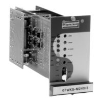
Kollmorgen Seidel 67WKS-M240/3-P0 Installation Manual (42 pages)
Brand:
Kollmorgen Seidel
| Category:
Inverter
| Size: 1 MB
Table of Contents
Table of Contents
3
1 I General Information
5
Introduction
5
I.1 Introduction
5
Equipment Concept
6
I.2 Equipment Concept
6
Functional Groups
7
I.3 Functional Groups
7
Specifications
8
I.4 Specifications
8
Permitted Ambient Conditions
9
Connectable Motor Types
9
Protective Functions
9
Isolating Transformers
10
I.8 Isolating Transformers
10
Installation Instructions
11
2 II Installation Instructions
11
II.1 Safety Instructions
11
II.2 Connection and Wiring
12
Conductor Cross-Sections
12
Ventilation
12
Fuse Protection
12
Backplane Pin Assignments of F/R67WKSMB
13
II.3 Checklist
15
Commissioning
16
3 III Commissioning
16
III.1 Safety Instructions
16
III.2
17
Instructions for Commissioning
17
III.3 Interference Suppression
17
III.2 Instructions for Commissioning
17
4 Functions and Options
18
IV.1 Safety Instructions
18
IV.2 Functional Description
18
Input Functions
18
Nominal Value Inputs In1, In2
18
Tachometer Input Ta
18
1:1 Control
19
Digital Control Inputs
19
Input Enable E
19
Limit Switch Inputs PSTOP, NSTOP
19
Armature Current Monitor Output IDC
20
IV.2.2 Output Functions
20
Measuring Points
20
Output Functions
20
Ready to Operate Contact (BTB)
20
Tachometer Monitor Output V-TA
20
IV.2.3 Possible Settings
21
Nominal Value Potentiometer P2
21
Offset Potentiometer P3
21
Possible Settings
21
Ramp Potentiometer P1
21
Tachometer Potentiometer P4, Tachometer Adjustment R310
21
A.C. GAIN Potentiometer P5
22
IV.2.3.5 A.C. GAIN Potentiometer P5
22
Peak Current I PEAK P6
22
Ballast Circuit with -W- Characteristic
23
IV.2.3.7 RMS Current I
23
IV.2.4 Other Functions
23
Other Functions
23
RMS , I²T Limit P7
23
Displays
24
Frequency Response of Controller
24
I²T Monitor
24
External 24 V Auxiliary Voltage
25
IV.3 Solder Straps and External Straps
25
IV.3.1 Solder Straps
25
Clock Frequency [LB2,3,4]
25
External 24 V D.C. Auxiliary Voltage [LB1]
25
RMS Current [LB5]
25
Current Nominal Value Strap
26
Digital GND, Analogue GND
26
External Straps
26
IV.3.2 External Straps
26
Operation Without Limit Switches
26
5 Drawings
27
Front View of 67WKS
27
Proposed Wiring Diagram 67WKS with SM35, SM45
28
Wiring Diagram 67WKS with SM35
29
Wiring Diagram 67WKS with SM45
30
Wiring Diagram 67WKS with SM56
31
Component Layout of Motherboard 67WKS
32
Component Layout of Ballast PCB 67WKS
33
Speed Control Circuit 67 WKS (Hybrid)
34
RPE, TA, Input Circuits 67WKS (Hybrid)
35
Backplane F67WKSMB
36
Backplane R67WKSMB
37
19" Shelf Comprising 67WKS, Front View
38
19" Shelf Comprising 67WKS, Rear View
39
3-Phase Isolating Transformers for 67WKS
40
6 Appendix
41
Advertisement
Advertisement
Related Products
Kollmorgen Seidel 67WKS-M240/3-PB
Kollmorgen Seidel 67WKS Series
Kollmorgen Seidel SERVOSTAR 614
Kollmorgen Seidel SERVOSTAR 610-30
Kollmorgen Seidel 6SM56 Series
Kollmorgen Seidel 6SM 45M-3000
Kollmorgen Seidel 6SM 56L-3000
Kollmorgen Seidel 6SM 71S-3000
Kollmorgen Seidel 6SM 100L-3000
Kollmorgen Seidel 60WKS-M240/3-PB
Kollmorgen Seidel Categories
Amplifier
Engine
Servo Drives
Inverter
Controller
More Kollmorgen Seidel Manuals
Login
Sign In
OR
Sign in with Facebook
Sign in with Google
Upload manual
Upload from disk
Upload from URL