Table of Contents
Advertisement
Quick Links
Advertisement
Table of Contents

Summary of Contents for Kollmorgen Seidel 67WKS-M240/3-PB
- Page 1 Transistorized — Inverter Series: 67WKS Manual Edition 10/00...
- Page 2 Technical changes improving performance and specifications, may be made without prior notice ! Printed in the Federal Republic of Germany 10/00 Mat.Nr.: 73885 Former releases: 08/91 All rights reserved. No part of this work may be reproduced in any form (by printing, photocopying, microfilm or any other method) or stored, processed, copied or distributed by electroninc means without the written permission of Seidel Corporation.
-
Page 3: Table Of Contents
Kollmorgen Seidel Contents 10.00 Contents D r a w i n g P a g e General information Introduction ..................1 Equipment concept . - Page 4 Contents Kollmorgen Seidel 10.00 Contents D r a w i n g P a g e Drawings Front view of 67WKS ................23 - E.4.945.4/02...
-
Page 5: I General Information
Kollmorgen Seidel General information 10.00 General information Introduction This manual explains how to install, commission, set and adjust the 67WKS transistor inverter. The manual is divided into 6 chapters: Chapter 1 General information Chapter 2 Installation instructions Chapter 3 Commissioning... -
Page 6: Equipment Concept
General information Kollmorgen Seidel 10.00 Equipment concept A four-quadrant controller for brushless DC servo motors (AC servo motors) based on the synchro- nous principle was accommodated on one single Eurocard using state-of-the-art components and hybrid technology. The output phase is designed as a 3-phase pulse-width-modulated transistor stage. The trapezoidal output currents and motor speed are controlled by PI controllers;... -
Page 7: Functional Groups
Kollmorgen Seidel General information 10.00 Functional groups The following functional groups are accommodated on a single Eurocard measuring 220x100x14 U designed in hybrid technology: 3-phase power supply with smoothing capacitor (-P-) Fuses for auxiliary voltage power supply and ballast circuit... -
Page 8: Specifications
General information Kollmorgen Seidel 10.00 Specifications Characteristics Unit 67WKS - M240 / 3 - PB Rated supply voltage 3 x 60...172 Rated connected power (for 3.5 A rated current) Rated d.c. voltage in intermediate circuit Rated output current Peak output current (available for max. 2.5 s) Max. -
Page 9: Permitted Ambient Conditions
Kollmorgen Seidel General information 10.00 Permitted ambient conditions Tolerance of supply voltages ±10% Installation position in 19" shelf vertical Non-ventilated with natural ventilation, rated specifica- tions, Ju<45°C and single-stage installation Forced ventilation at Ju> 45°C or for installation in several stages Ambient temperature (at rated values) 0 to +45°C... -
Page 10: Isolating Transformers
General information Kollmorgen Seidel 10.00 Isolating transformers Isolating transformers are required to operate the controllers. To ensure the proper operation of the equipment and compliance with warranty conditions, the iso- lating transformers must conform with the specifications listed below. Model: 3-phase isolating transformers with shielding winding according to VDE 0550 in Y/y or Y/d connection. -
Page 11: Installation Instructions
Kollmorgen Seidel Installation instructions 10.00 Installation instructions II.1 Safety instructions Check the rating plate on the controller. Compare the rated voltage and rated current with the transformer and motor characteristics. The front panel of the modules is only protected against accidental contact if the modules are mounted in the 19"... -
Page 12: Ii.2 Connection And Wiring
Installation instructions Kollmorgen Seidel 10.00 II.2 Connection and wiring In addition to correct grounding of equipment and motor housings, proper wiring by qualified per- sonnel is also very important for functional reliability. The motor conductors must be stranded with sufficient cross-sectional area (for single conduc- tors) or installed in cables (oil-resistant flexible cables, etc.). -
Page 13: Backplane Pin Assignments Of F/R67Wksmb
Kollmorgen Seidel Installation instructions 10.00 II.2.4 Backplane pin assignments of F/R67WKSMB XST401 9-pin Signal name sub-D (pin no.) on a.c. tachometer Abbreviation +15 V for RPE +15 V Tachometer centre point Ta-Mp Tachometer phase W Ta-W Tachometer phase V Ta-V... - Page 14 Installation instructions Kollmorgen Seidel 10.00 XST404 Combicon block (terminal no.) 60WKSMB, type Abbreviation Signal name Signal direction (solder print) Nominal value 1+, ±10 V Input SW1+ Nominal value 1-, ±10 V Input SW1- Nominal value 2+, ±10 V Input SW2+ Nominal value 2-, ±10 V...
-
Page 15: Ii.3 Checklist
Kollmorgen Seidel Installation instructions 10.00 II.3 Checklist — Check rating plates — Select correct wiring diagram — Select conductors as described in Section II.2.1 — Determine common grounding point — Ground transformer (core and shielding winding) — Ground motor housing —... -
Page 16: Commissioning
Commissioning Kollmorgen Seidel 10.00 Commissioning III.1 Safety instructions Check whether the safety instructions in Section II.1 have been fulfilled. Read the instructions for commissioning contained in Section III.2 The correct sequence of steps for commissioning helps you to prevent damage. Please con- tact us if you require any further information. -
Page 17: Iii.2
Kollmorgen Seidel Commissioning 10.00 III.2 Instructions for commissioning Commissioning is only summarized here. We can provide you with further information at our trai- ning courses (on request). Check the wiring using the wiring diagram (transformer and RPE terminal, ground- ing, motor terminal, control signals). -
Page 18: Functions And Options
Functions and options Kollmorgen Seidel 10.00 Functions and options IV.1 Safety instructions First read Chapter IV before you make changes any changes to the controller. The controller can only be modified by trained qualified personnel. You are allowed to adjust and optimize the controller and connect circuit parts by solder straps. -
Page 19: Digital Control Inputs
Kollmorgen Seidel Functions and options 10.00 IV.2.1.3 Digital control inputs Enable (E, terminal 16), H level for controller enable. 1:1 control (1:1, terminal 15), H level to switch off integral section. Limit switch positive/negative (PSTOP/NSTOP, terminals 10/11), H level in normal mode (open-circuit-proof). -
Page 20: Output Functions
Functions and options Kollmorgen Seidel 10.00 IV.2.2 Output functions IV.2.2.1 Armature current monitor output IDC The output (terminal 19) supplies ±10 V for ± equipment peak current connected to AGND, output impedance 2kW. The d.c. rms voltage of all three phases, which is approximately proportional to the supplied motor torque, is generated. -
Page 21: Possible Settings
Kollmorgen Seidel Functions and options 10.00 IV.2.3 Possible settings IV.2.3.1 Ramp potentiometer P1 You can adjust the rise time for a nominal value step using potentiometer P1. This only acts on nominal value input 2! You can select the maximum rise time of about 10 ms per nF for a nominal value step of 10 V using C306 when the potentiometer is turned to the ccw stop. -
Page 22: A.c. Gain Potentiometer P5
Functions and options Kollmorgen Seidel 10.00 IV.2.3.5 A.C. GAIN potentiometer P5 You can increase the proportional gain of the PI speed controller by turning the potentiometer P5 clockwise (control becomes stiffer). When the potentiometer is turned to the ccw stop, R307 sets the basic gain to approx. -
Page 23: Iv.2.3.7 Rms Current I
Kollmorgen Seidel Functions and options 10.00 IV.2.3.7 RMS current I , I²t limit P7 The controller is capable of supplying the equipment peak current I = 10A for a maximum PEAK period of 2.5s. The current is then limited to the set rated current I . -
Page 24: Frequency Response Of Controller
Functions and options Kollmorgen Seidel 10.00 IV.2.4.2 Frequency response of controller The basic setting of the frequency response of the current controller is designed for a bandwidth of 1 kHz, which means that the delay time is negligibly small. IV.2.4.3 I²t monitor... -
Page 25: External 24 V Auxiliary Voltage
Kollmorgen Seidel Functions and options 10.00 IV.2.5 External 24 V auxiliary voltage In the as-delivered state, the auxiliary voltage power supply is fed from the d.c. intermediate circuit (80 to 240 V). If you wish to store the fault signals in the memories after the intermediate circuit voltage is swit- ched off, you can supply the auxiliary power supply from an external 24 V d.c. -
Page 26: External Straps
Functions and options Kollmorgen Seidel 10.00 IV.3.2 External straps IV.3.2.1 Digital GND, analogue GND In the as-delivered state, DGND (terminal 12) and AGND (terminal 17) are not connected. To obtain a common GND reference point for digital and analogue signals, you must strap the ter- minals 12 and 17 externally. -
Page 27: Drawings
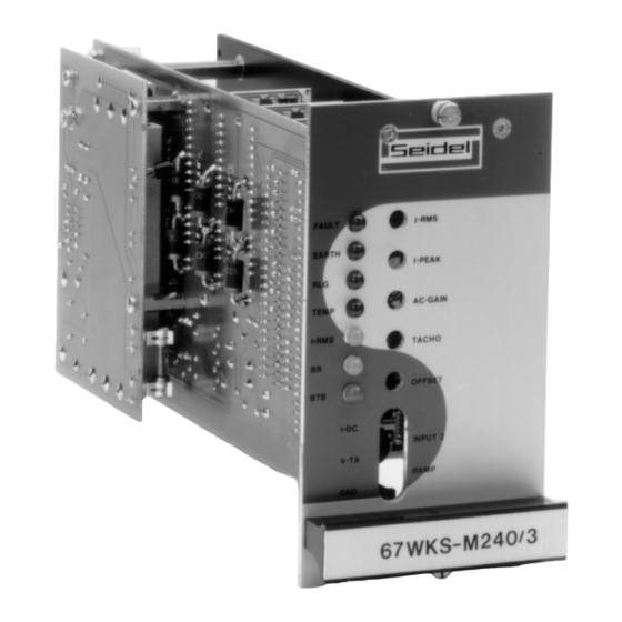
Kollmorgen Seidel Drawings 10.00 - E.4.945.4/02 Drawings Front view of 67WKS - E.4.945.4/02 67WKS Installation Manual... -
Page 28: Proposed Wiring Diagram 67Wks With Sm35, Sm45
Drawings Kollmorgen Seidel 10.00 - E.4.945.1/03 Proposed wiring diagram 67WKS with SM35, SM45 - E.4.945.1/03 67WKS Installation Manual... -
Page 29: Wiring Diagram 67Wks With Sm35
Kollmorgen Seidel Drawings 10.00 - E.4.945.1/02 Wiring diagram 67WKS with SM35 - E.4.945.1/02 67WKS Installation Manual... -
Page 30: Wiring Diagram 67Wks With Sm45
Drawings Kollmorgen Seidel 10.00 - E.4.945.1/01 Wiring diagram 67WKS with SM45 - E.4.945.1/01 67WKS Installation Manual... -
Page 31: Wiring Diagram 67Wks With Sm56
Kollmorgen Seidel Drawings 10.00 - E.4.945.1/16 Wiring diagram 67WKS with SM56 - E.4.945.1/16 67WKS Installation Manual... -
Page 32: Component Layout Of Motherboard 67Wks
Drawings Kollmorgen Seidel 10.00 - E.4.945.2/02 Component layout of motherboard 67WKS - E.4.945.2/02 67WKS Installation Manual... -
Page 33: Component Layout Of Ballast Pcb 67Wks
Kollmorgen Seidel Drawings 10.00 - E.4.945.2/01 Component layout of ballast PCB 67WKS - E.4.945.2/01 67WKS Installation Manual... -
Page 34: Speed Control Circuit 67 Wks (Hybrid)
Drawings Kollmorgen Seidel 10.00 - E.4.945.1/14 Speed control circuit 67 WKS (hybrid) - E.4.945.1/14 67WKS Installation Manual... -
Page 35: Rpe, Ta, Input Circuits 67Wks (Hybrid)
Kollmorgen Seidel Drawings 10.00 - E.4.945.1/15 RPE, TA, input circuits 67WKS (hybrid) - E.4.945.1/15 67WKS Installation Manual... -
Page 36: Backplane F67Wksmb
Drawings Kollmorgen Seidel 10.00 - E.4.945.4/01 V.10 Backplane F67WKSMB - E.4.945.4/01 67WKS Installation Manual... -
Page 37: Backplane R67Wksmb
Kollmorgen Seidel Drawings 10.00 - E.4.945.4/07 V.11 Backplane R67WKSMB - E.4.945.4/07 67WKS Installation Manual... -
Page 38: 19" Shelf Comprising 67Wks, Front View
Drawings Kollmorgen Seidel 10.00 - E.4.945.4/03 V.12 19" shelf comprising 67WKS, front view - E.4.945.4/03 67WKS Installation Manual... -
Page 39: 19" Shelf Comprising 67Wks, Rear View
Kollmorgen Seidel Drawings 10.00 - E.4.945.4/04 V.13 19" shelf comprising 67WKS, rear view - E.4.945.4/04 67WKS Installation Manual... -
Page 40: 3-Phase Isolating Transformers For 67Wks
Drawings Kollmorgen Seidel 10.00 - E.4.945.4/05 V.14 3-phase isolating transformers for 67WKS - E.4.945.4/05 67WKS Installation Manual... -
Page 41: Appendix
Kollmorgen Seidel Appendix 10.00 Appendix VI.1 Ordering information Order No. Name, part Material No Equipment, description Transistor inverter 67WKS-M240/3-PB 71927 Power supply, ballast circuit, 1 ferrite core 67WKS-M240/3-P0 72195 Power supply, no ballast circuit, 1 ferrite core ### Please quote the motor type used when ordering equipment. - Page 42 It alien / It aly / I t alie Ge rmany / Al lemag ne DIGIMATIC A/S M.C.A. s.r.l. "Laerkenfeldt" Via f. Turati 21 Kollmorgen Seidel GmbH & Co. KG Aalkaergaardvej 20 20016 Pero (Mi) Verkaufsniederlassung Nord 8700 Horsens Nord Tel.: +39(0)02 - 33 91 04 50 Wacholderstr.
Need help?
Do you have a question about the 67WKS-M240/3-PB and is the answer not in the manual?
Questions and answers