Sign In
Upload
Manuals
Brands
Koden Manuals
Marine Radar
MDC-7025P
Koden MDC-7025P Manuals
Manuals and User Guides for Koden MDC-7025P. We have
2
Koden MDC-7025P manuals available for free PDF download: Operation Manual, Installation Manual
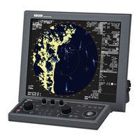
Koden MDC-7025P Operation Manual (232 pages)
Brand:
Koden
| Category:
Marine Radar
| Size: 3 MB
Table of Contents
Document Revision History
3
Important Notice
4
For Your Safe Operation
5
Break in Procedure of Stored Radar
14
Used Battery and Radar Disposal
15
Table of Contents
16
Introduction
23
Configuration Items
24
System Configuration
24
Chapter 1 Display and Operation
27
Radar Display
27
Upper Left Corner
27
Upper Right Corner
28
Lower Left Corner
28
Lower Right Corner
28
Own Ship Data
29
Target Status
29
Target and MAP Information Area
30
Assistant Display (Navigation Information)
31
Alert Display Area
32
Operation Unit
34
Menu Usage
36
Turn MENU on and off
36
Select Menu Item
36
Display [MAINTENANCE] Menu
37
Cursor Access Usage
37
Chapter 2 Radar Basic Operation
39
Power ON/OFF
39
Power on
39
Power off
39
Change Brilliance
40
Display Brilliance
40
Operation Unit Brilliance
40
Transmission
41
Transmission on
41
Transmission off
41
Tuning Method
42
Change man (Manual) and AUTO
42
Optimized Value Setup Method
42
Change Range Scale
43
Change Range Unit (NM / Km)
43
Adjust Receiver Gain (GAIN)
44
Selection of man GAIN and AUTO GAIN
44
AUTO Adjustment of GAIN
44
MAN Adjustment of GAIN
45
Reject Sea Clutter (Anti-SEA)
46
Selection of man SEA and AUTO SEA
46
AUTO Adjustment of SEA
47
Manual Adjustment of SEA
47
Reject Rain/Snow Clutter (Anti-RAIN)
48
Changing Method of CFAR and man
49
CFAR (Constant False Alarm Rate) Adjustment
49
RAIN man (Manual) Adjustment
50
Change Transmission Pulse Width (SP/LP)
51
Select Display Mode
52
For H up (Head up Mode)
52
For C up (Course up Mode)
53
For N up (North up Mode)
54
For Relative Motion (RM) and True Motion (TM)
55
Reset True Motion
56
Ground and Sea Stabilization
57
SEA (Sea Stabilization)
57
GND (Ground Stabilization)
58
Measurement of Distance by RR and VRM
59
Display Range Rings (RR)
59
Measurement Range (VRM: Variable Range Marker)
60
Measurement Range (Cursor)
60
Measurement of Bearing by EBL
61
Using the EBL OFFSET
62
Bearing Mode Set up
63
Measurement of Distance/Bearing by PI
64
Measurement Distance/Bearing by ERBL
66
Change ERBL Mark to LINE or RING
67
Change ERBL Offset Method
67
Change Color and Brightness (Day/Night)
68
Setup Color
68
Setup Brightness
68
Color and Brightness Settings Reset
68
Remove the Heading Line/Navigation Data
69
Target Trail
69
Relative Display (R)
71
True Display (T)
71
Off Center
72
Function Key Usage
73
Set Picture Mode
74
Echo Process
75
Correlation Image Echo Process
75
Echo Expansion
76
Interference Rejection (IR)
77
Video Contrast
77
Noise Rejection
78
Echo Color Rejection
78
Pulse Width
79
Receiving Radar Beacons, SART and Radar Enhancer
80
Inter-Switch
82
Cursor Data
84
CURSOR Setting Menu
84
Performance Monitor
85
Reference Position and Display Center
86
Reference Position
86
Display Center
86
Antenna Position Mark on or off
87
Setup Own Ship Outline
88
Setup CCRP Number and Ship Outline
88
Ferry Mode
89
Chapter 3 Operation Alarm
91
Collision Avoidance
91
Echo Alarm
91
How to Set Echo Alarm Area (Fan Type)
91
Map Area Alarm
93
How to Edit Map Area
93
How to Move Map Area
94
How to Add Data to Map Area
95
How to Delete the Data of Map Area
96
How to Clear Entire Block of Map Area Data
96
Guard Zone Alarm
97
How to Set Guard Zone Alarm
97
Nav Line Cross
98
How to Edit
98
How to Move Nav Line
99
How to Add
100
How to Delete
101
How to Clear
101
Alarm On/Off (TT and AIS)
102
Chapter 4 Alert
103
Alert List
103
Alert History List
104
Operation Note
105
Hardware Note
106
Chapter 5 Target (AIS, TT and Trial Manoeuvre)
107
Common Setting
107
Vector Rel/True
107
CPA/TCPA Alarm
109
Lost Alarm
109
Set AIS ID DISP TYPE
110
Set TT ID DISP TYPE
110
Set ID DISP SIZE
111
Set Input Range
111
Association
112
Automatic Acquisition Area
113
PAST POSN: Past Position
114
Ais
115
Enable AIS Function
116
Select ID
116
Active/Sleep
116
Ship Outline
116
HDG Line
116
Turn Indicator
117
OS Display
117
Os Mmsi
117
Message Display
117
AIS Filter
118
AIS Alert [Sleeping Lost]
119
AIS Auto ACQ
119
Types of AIS Target Symbol
120
Tt (Arpa)
123
Limitations of the TT Function
123
Enable TT Function
124
Manual Acquisition
124
Delete TT Target
125
Delete All TT Targets
125
Reference Target Acquisition
126
Types of Tracked Target Symbol
128
Test Tgt
129
Function Check
134
Auto Acquisition
138
Trial Manoeuvre
140
Chapter 6 Nav Tool
143
Guard Line
143
HL Blink
144
Stern Line
144
Barge Icon
145
Chapter 7 Map Operation
147
MAP Function Display on or off
147
Own Ship Past Track
147
How to Clear OWN SHIP PAST TRACK
148
Target Track Past Position Display
148
Coast Line
149
How to Edit
149
How to Move
151
How to Add
152
How to Delete
153
How to Clear
153
Nav Line
154
Route
155
Event Mkr
156
Area
157
Monitored Route
158
Wpt ID Disp
158
Target Track ID
158
Datum
159
Edit User Datum
159
Position Offset
160
Position Manual Offset
160
Gps Buoy
161
Wpt Flag
162
Lat/Lon Line
162
C-MAP Chart Display
162
Chapter 8 System and Maintenance Menu Operation
163
System Menu
163
Change UTC / LOCAL Time
163
User Memory
164
Change USER Memory
164
How to Save to Memory
164
Edit User Name
164
Default User Setting
164
Sound Setting
165
Sound ON/OFF
165
Sound Frequency
165
Key Click ON/OFF
165
External Buzzer Setting
165
HELP Window ON/OFF
166
Maintenance Menu
167
BACKUP of Setup Data (Cannot be Used While Transmitting)
167
Internal Save of Setup Data
167
External Save of Setup Data (Cannot be Performed While Transmitting)
168
Parameter Reset
168
TOTAL HOUR and TX HOUR (Cannot be Used While Transmitting)
169
Menu Setup
169
System Program
170
Version Confirmation
170
How to Update the System Program
170
Chapter 9 Principal of Radar System
171
What Is Radar System
171
Side Lobe
171
Beam Width
172
Characteristics of Radar Radio Wave
172
Target Hardness Reflected
172
Radar Shadow
173
False Image
173
Radar Interference
175
Chapter 10 Simple Fault Diagnosis
177
No Alarm Sound
178
Operation Unit (Panel) Key Is Not Operational
179
TT Is Not Operational
180
No AIS Display
181
Need to Confirm Serial Input
182
No Radar Video Display
183
Frozen Display
184
Indication of Presentation Failure
184
Alert Display Area
185
Alert List
186
Operation Note
188
Hardware Note
190
Chapter 11 Specifications
193
Antenna and Scanner Unit (Exposed)
193
Display, Processor and Operation Unit (Protected)
194
External View and Dimensions
195
Chapter 12 Appendix
199
Menu Tree
199
Input Data
210
Validity and Integrity of Input Data
210
Details of the Data Input Format
210
Set and Drift
211
Time and Date
212
Alert Handling
213
Details of TT Tracking Data Output
218
Details of the Radar Data Output
219
Radar System Data
219
Event Message
221
Interface Specification
222
NAV and EPFS Serial Data Input/Output Specification
222
SDME Serial Data Input/Output Specification
223
VDR (External Monitor) and Alarm Output Signal Specification
224
Alarm Contact Specification
225
Serial Data Input/Output Specification (AIS)
225
Radar Input/Output Signal Specification
226
Talker Device Code of the Data Output Devices
227
Priority of Talker Device Code
227
Chapter 13 Index
229
Advertisement
Koden MDC-7025P Installation Manual (152 pages)
Brand:
Koden
| Category:
Marine Radar
| Size: 3 MB
Table of Contents
Document Revision History
3
Table of Contents
4
Precaution for Operation
9
Caution about Rotating Antenna
9
Caution about Health Risks Caused by Radio Wave
9
Caution about Dangerous Internal High Voltage in the Device
9
Preface
9
Precautions for Maintenance
10
Caution against Residual High Voltage
10
Keep Inboard Power Source "Off
10
Caution against the Dust
10
Measures against Static Electricity
10
Break in Procedure of Stored Radar
10
Chapter 1 Prior to Installation
11
Installation Precautions
11
Unpacking of Components
11
Appearance Verification of each Unit and Accessories
11
Selection of Location for Installation
11
Antenna Scanner Unit
12
Display Unit and Operation Unit
13
Cable Wiring and Interconnection
14
Antenna Scanner Unit
14
Display Unit
14
Chapter 2 System Configurations
15
Standard Configuration List
15
Spare Parts List
19
Installation Material List
19
Options
20
MDC-7912P/7925P Series System Configuration
21
MDC-7012P/7025P Series System Configuration
22
Chapter 3 Installation Method
23
How to Install the Antenna Scanner Unit
23
Installation of the Antenna Scanner Unit
24
Mounting Antenna
25
Installation of the Connecting Cable CW-845-XXM
26
MDC-7012P/7912P (Scanner Unit RB808P)
26
MDC-7025P/7925P (Scanner Unit RB809P)
32
Interconnection Diagram of Cable
38
Installation of the Display Unit
39
Installation of MRD-108P
41
Tabletop Mounting of MRD-108P
41
Flush Mounting for MRD-108P
43
Installation of Operation Unit
44
Flush Mounting the Operation Unit
46
Installation of MRM-108P
47
Cable Connection to a Display Unit
48
Cable Connection for MRD-108P
48
Connecting an External Monitor
49
Connecting a VDR or External Monitor & Failure Alarm Output
49
Connecting a Gyro Converter Unit or THD
50
Connecting a Junctin Box JB-35 to Gyro, OTHER and Inter-Switch Data
51
AIS Cable Connection
52
Cable Connection for EPFS and SDME or Log
53
Cable Connection for Inter-Switch
54
Cable Connection Instructions for Cross-Over, Dual and Independent Connection
54
Cable Connection for Slave Display Used as a Monitor
55
Chapter 4 Setup after Installation
57
Display [MAINTENANCE] Menu
58
How to Change Protected Menu PASSWORD
58
STARTUP Menu
58
Tune Adjustment (TUNE)
58
Heading Adjustment (HL OFFSET)
59
Transmitting Delay Time Adjustment (TX DELAY)
60
Ant Height
60
Ant Cable
61
Main Bang Suppression (MBS)
61
Setup SEA (STC) Curve
62
Function Key Usage
63
Range Enable
64
Times Enable
65
Monitor Size
66
Ferry Menu
66
Setup I/O Interface
67
Select Heading Interfaces
68
Speed Interfaces
68
Setup Speed through Water (STW)
68
Select Speed over Ground (SOG) Interface
69
Select POSITION Interface
70
Select SET/DRIFT Input
71
Setup TIME
71
Alarm Output
72
Setup Output
72
Serial Data Output
73
Limiting of Type of Signal to Input Port
74
Changing Formats of Input/Output Ports of Navigation Devices, Position and Ship Speed
75
Setup KGC (GPS Compass)
76
Serial Monitor
77
Setup SECTOR MUTE Mode (Cannot Use While Transmitting)
77
Setup PRESET
77
RAIN MIN (man and CFAR Mode)
77
Setup RAIN MIN and MAX Mode
77
RAIN MAX (man and CFAR Mode)
78
SEA MIN (man and AUTO Mode)
79
Setup SEA MIN and MAX Mode
79
SEA MAX (man and AUTO Mode)
80
Setup GAIN MIN and MAX Mode
81
GAIN MIN (man and AUTO Mode)
82
GAIN MAX (man and AUTO Mode)
83
Setup GAIN OFFSET Mode
83
Setup SEA OFFSET Mode
84
BACKUP of Setup Data (Cannot be Used While Transmitting)
84
Internal Save of Setup Data
84
External Save of Setup Data (Cannot be Performed While Transmitting)
85
Parameter Reset
85
TOTAL Hour and TX Hour (Cannot Use While Transmitting)
85
MENU Setup
86
MON (Performance Monitor)
87
Initial Setup Methods
87
Confirmation Methods for Degradation of Antenna Performance after Operation
88
System Program
88
Version Confirmation
88
How to Update the System Program
89
Chapter 5 Troubleshooting and on Board Repair
91
Necessary Information at the Time of Repair Request
91
Provided Self Diagnostic Facilities
91
Alarm Display and How to Cancel
91
Alarm Display List
92
Operation Note Display
96
Malfunction Diagnostics
98
Malfunction Detection Step
98
Malfunction Diagnostics Flow Chart
99
Initial Malfunction Diagnostics
99
Cannot Turn on the Power
100
No Display
101
No Response from the Antenna Unit
102
Operation Unit Error
103
No Radar Echo
104
Weak Sensitivity of the Radar Echo
105
Data such as Heading, Speed, Latitude/Longitude Cannot be Received
106
Ais
107
Antenna Unit Failure
108
On Board Repair
114
Replacement of Fuse
114
Replacement of Internal Battery
115
Chapter 6 Maintenance
117
List of Parts that Have Longevity
117
Regular Service and Cleaning up
118
Monthly Inspection
118
Method of Exchanging the Magnetron
119
Magnetron Replacement (RB808P)
119
Magnetron Replacement (RB809P)
123
Chapter 7 Input/Output Data
127
Input Data
127
Validity and Integrity of Input Data
127
Details of the Data Input Format
127
Details of TT Tracking Data Output
136
Details of the Radar Data Output
137
Interface Specification
140
NAV and EPFS Serial Data Input/Output Specification
140
SDME Serial Data Input/Output Specification
141
VDR (External Monitor) and Alarm Output Signal Specification
142
Circuit for Horizontal Sync, Vertical Sync Signal Output
142
Circuit for R, G, B Video Signal Output
142
Alarm Contact Specification
143
Serial Data Input/Output Specification (AIS)
143
Radar Input/Output Signal Specification
144
Talker Device Code of the Data Output Devices
145
Priority of Talker Device Code
145
Inter Connection Diagram (Rb808P
147
Inter Connection Diagram (Rb809P
148
Inter Connection Diagram (Mrd-108P/Mro-108P
149
Inter Connection Diagram (Mrm-108P/Mro-108P
150
Advertisement
Related Products
Koden MDC-7006
Koden MDC-7012
Koden MDC-7025
Koden MDC-7060
Koden MDC-7010
Koden MDC-7020
Koden MDC-7000P series
Koden MDC-7012P
Koden MDC-7906
Koden MDC-7912P
Koden Categories
Marine Radar
Marine Equipment
GPS
Sonar
Monitor
More Koden Manuals
Login
Sign In
OR
Sign in with Facebook
Sign in with Google
Upload manual
Upload from disk
Upload from URL