Sign In
Upload
Manuals
Brands
Koden Manuals
Marine Radar
MDC-2000 series
Koden MDC-2000 series Manuals
Manuals and User Guides for Koden MDC-2000 series. We have
1
Koden MDC-2000 series manual available for free PDF download: Operation Manual
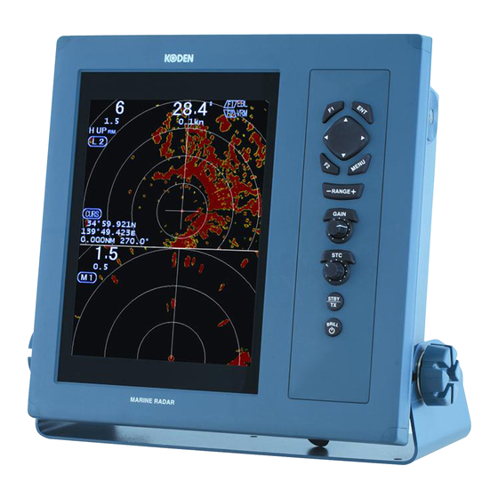
Koden MDC-2000 series Operation Manual (82 pages)
Brand:
Koden
| Category:
Marine Radar
| Size: 2 MB
Table of Contents
Document Revision History
3
Important Notices
4
For Your Safe Operation
5
Table of Contents
9
Contents
10
Introduction
12
System Configuration
13
Configuration of Equipment
14
Chapter 1 Basic Operation
17
How to Read the Radar Screen
19
How to Use the Keys
20
Power On/Off
22
Power on
22
Power off
22
Language Selection at Initial Start-Up
22
Brilliance Adjustment
22
Brightness Adjustment of LCD
22
Brightness Adjustment of Panel
22
Transmission
22
Start of Transmission
22
Stop of Transmission
22
Switch-Over of Range
23
Change of Range
23
Change of Sub-Screen Range
23
Gain Adjustment
23
Adjustment of Sub-Screen Gain
23
STC Adjustment
24
Use of [F1] and [F2] Keys
24
How to Use [F1] and [F2] Keys
24
1.10 Delete of Heading Line
25
Use of Crosshair Cursor
25
Measuring the Distance and Bearing between Two Points
26
Measuring the Distance and
26
1.13 Camera Display
26
How to Connect a CCD Camera
26
How to Display the Video of a
26
CCD Camera
26
Chapter 2 How to Use the Menu
27
How to Operate the Menu
27
Display/Non-Display of Menu
27
Operation of Menu
27
FTC Adjustment
28
Setting of Display Mode
28
H up (Head Up)
28
N up (North Up)
29
C up (Course Up)
29
WPT up (Waypoint Up)
29
Relative Motion (RM) and True
29
Motion (TM)
29
True Motion Reset
31
Display Select
31
PPI Display
31
PPI/PPI Display
31
Note on PPI/PPI Display
32
PPI/NAV Display
32
Note on PPI/NAV Display
32
Setting of off CENTER
32
Setting of Enhance (Enlarged Target)
32
Setting of Signal Process
32
Setting of Pulse Width
33
Trailing
33
Relative Display (R)
33
True Display (T)
34
2.10 Ebl
34
2.11 Vrm
34
2.12 Display Color
35
2.13 Crosshair Cursor Shape
35
PI (Parallel Index Line)
35
2.15 Bearing Mode
35
2.16 Vector
35
2.17 Alarm
36
IN Mode
36
OUT Mode
36
Setting of Alarm Range
36
2.18 Sleep
36
Operation During Executing the Sleep
37
2.19 Ais
37
Setting of Symbol Display of
37
Setting of Detailed Information of
37
Designated Symbol Display
37
Types and Meanings of AIS
37
Symbols
37
2.20 Ata
38
Automatic Acquisition
38
Manual Acquisition
39
Target Level
39
Target Delete
39
Number of Acquisition
39
Information Display
39
Types and Meanings of ATA
40
Symbols
40
Chapter 3 How to Use the System Menu
41
Display of System Menu
41
Display the System Menu
41
Return to the Normal Menu
41
Setting of Assist Items
41
Range Rings
41
Range Unit
41
Speed Unit
41
Temperature Unit
41
Depth Unit
41
WPT Display
42
Rotation Speed
42
All Ppi
42
Guide
42
Buzzer
42
Motor Speed
42
N Up/S up
42
Crosshair Cursor Display
42
Radar Setting Display
42
Menu Operation
42
Bearing Setting
43
TX Delay Adjustment
43
Mbs
43
STC Curve
44
Tune Select
45
Automatic Tuning
45
Manual Tune Adjustment
45
Pulse Width
45
Interference Rejection
46
Echo Color Divide
46
Signal Select
46
Field of Angle
46
Nmea
47
Setting (Connection with the KODEN GPS Compass)
47
Preset
47
F1/F2 Key Set
47
Select Range S/M/L
47
Echo Color Set
47
Trail Color Set
47
Display Color Set
47
Language Select
47
NAV Display Select
47
Maintenance
48
Display Unit
48
Antenna
48
Panel Test
48
LCD Test
48
Operation Hours Reset
48
TX Hours Reset
48
ALL Reset
48
System Program Renewal
48
Chapter 4 Maintenance
49
4.1 Maintenance
49
4.1.1 Monthly Inspection
49
4.1.2 Yearly Inspection
50
Fuse Replacement
51
Consumables
51
Trouble Diagnosis
51
Information Required for Requesting a Repair
51
Error Display
51
Self-Diagnostic Function
52
Inspection at each Location
53
Chapter 5 Equipment
54
Antenna Installation
54
Determining the Location of the Installation
54
How to Shift the Antenna from an Obstacle
55
Installation of Antenna
56
Installation of Radome Antenna
56
Setting of Open Antenna
57
Installation of Antenna
58
Cable Connection
60
Mutual Connection Diagram
63
Display Unit Installation
64
Desktop Installation
64
Flush-Mount Installation
65
Adjustment after Installation
66
Wiring
67
Cable Connection to the Display Unit
67
Connection of DC Power Cable
69
Grounding
69
Connection of External Buzzer and External Monitor
69
Connection with the AIS
70
Receiver
70
Connection with the Navigation Equipment
70
Connection of CCD Camera
70
List of Input/Output Sentence
71
Input Sentence
71
Output Sentence
71
Chapter 6 Attached Table
72
Menu Configuration
72
Specifications
74
External View
75
Chapter 7 Principle of Radar System
78
What Is the Radar System
78
Side Lobe
78
Beam Width
78
Characteristics of Radar Radio Wave
79
Target with Less Reflection
79
Radar Shadow
79
False Image
79
Radar Interference
81
Advertisement
Advertisement
Related Products
Koden MDC-2000BB Series
Koden MDC-2003BB
Koden MDC-2005BB
Koden MDC-2004BB
Koden MDC-2006BB
Koden MDC-2000A Series
Koden MDC-2060BB
Koden MDC-2012BB
Koden MDC-2010BB
Koden MDC-2041A
Koden Categories
Marine Radar
Marine Equipment
GPS
Sonar
Monitor
More Koden Manuals
Login
Sign In
OR
Sign in with Facebook
Sign in with Google
Upload manual
Upload from disk
Upload from URL