Sign In
Upload
Manuals
Brands
Kistler Manuals
Amplifier
5080A Series
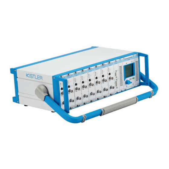
Kistler 5080A Series Charge Amplifier Manuals
Manuals and User Guides for Kistler 5080A Series Charge Amplifier. We have
1
Kistler 5080A Series Charge Amplifier manual available for free PDF download: Instruction Manual
Kistler 5080A Series Instruction Manual (117 pages)
Charge Amplifier
Brand:
Kistler
| Category:
Amplifier
| Size: 7 MB
Table of Contents
Table of Contents
4
For Your Safety
8
Unpack
9
Transportation and Storage
9
Electromagnetic Compatibility (EMC)
10
Tips for Using this Manual
11
Instrument Versions
12
Accessories Included
13
Optional Accessories
13
Manual Nomenclature
15
Units of Measure
16
Piezoelectric Measurement Concept
17
Drift Compensation of Piezoelectric Amplifier Type 5080A
21
For Cylinder Pressure Signals
21
Disposal Instruments for Electrical and Electronic Equipment
22
Block Diagram
24
6-Component Force-Moment Measurement
25
Amplifier Unit
26
Control Unit
27
Power Supply Unit
28
The Measuring Chain
29
Multi-Component Force Measurements with Dynamometers
30
3-Component-Force Measurement with 3-Channel Charge Amplifier and a Stationary Dynamometer
30
4-Component-Force-Moment Measurement with 4-Channel Charge Amplifier and a Stationary Dynamometer
30
6-Component-Force-Moment Measurement with 8-Channel Charge Amplifier and a Stationary Dynamometer
31
(6-) Component-Force-Moment Measurement with 8-Channel Charge Amplifier and a Measuring Hub
32
User Interface
33
Inserts and Connections
34
Inserting Amplifier Modules and Interfaces
37
Connecting the Instrument
38
Connecting Cable Adaptor Type 5435A
38
EMC and Ground Loops
39
Instrument Operation
41
Display and Main Menu
41
Menu Operation
42
Select Language
42
Set Numerical Values
42
Step by Step Measuring Guidance
43
3-Component-Force Measurement
43
Signals on Analog Output
48
6-Component-Force Moment Measurements
49
Sensor Distances
49
Correction Factors
50
Application: 'General Force' Vs 'Wheel Force
50
Signals on Analog Output in 'General Force' Application
51
Signals on Analog Output in 'Wheel Force' Application
51
Remote Control and Triggering
52
Software
53
Contrast Setting
54
Lock/Unlock Settings
54
Channel Selection
54
Summation
55
Scaling
55
Sensor Distances
57
Correction Factors
57
General Force' Vs. 'Wheel Force
58
Actuate Output
58
Menu
58
Measuring Range
58
Stepwise Range Setting
59
Variable Range Setting
59
Mechanical Unit
59
Sensor Sensitivity Value
60
Sensor Sensitivity Unit
61
Display of Measuring Value
62
High-Pass Filter
62
Low-Pass Filter
62
Voltage Output Scaling
63
Display of Active Drift Compensation
63
Trigger Display
64
Parameter Set Display
64
Demo Mode
65
Select Language
65
Display of Instrument Information
66
Communication RS-232C / USB Interface
66
Function Key Definition
66
Control Measuring Cycle
67
Use of Minidin Interface as a Remote Control
69
Use of RS-232C Interface on Interface Type 5245 to Trigger
69
Use of RS-232C Interface on Interface Type 5245 as a Remote Control
70
Zero Error Adjustment
70
Storing, Recalling and Clearing Parameter Sets
71
Channel Copying
71
Storing a Parameter Set
72
Recalling a Parameter Set
73
Clearing a Parameter Set
74
Factory Defaults
75
Signal Display
75
Piezotron
76
Messages
76
Commands for RS-232C Interface
77
Extended Instruction Record of the RS-232C Interface
80
Event Messages
84
Message Format
84
Event Messenger from Measure Card
85
Event Messenger from CPU
85
LED Signaling
85
Charge Input
86
Low Impedance (Piezotron)/Voltage Input on Dual Mode Module Type 5067A2
86
Voltage Output on Charge Amplifier/Dual Mode Module Type 5067
87
Frequency Response on Charge Amplifier/Dual-Mode Module (Type 5067A0/5067A2)
88
Time Constant (Short / Medium)
88
Time Constant (Long)
88
Drift Compensation (Drco)
88
Low-Pass Filter
89
Voltage Output on Summing Calculator Interface (Type 5245)
92
Specifications Without Piezotron Option
92
Specifications with Piezotron Option
93
Charge Input on Fischer Connector (on Type 5435A
94
Refresh Rate LCD
95
Remote Control (Type 5067)
95
Remote Control (Type 5245)
95
Data Communication
96
Power Supply Connection
97
Environmental Data
98
Precautions
101
Causes of Drift
101
Testing and Calibration
103
Instrument Test
103
Calibration
103
Kistler Calibration Service
104
Loading New Firmware
104
Changing Fuses
105
Remote Control Connection
106
RS-232C Cable
107
Charge Amplifier Transfer Function
108
High-Pass Filter
108
Dynoware Type 2825A
110
3-Component Force Measurement F Type 5080Axx3X001 and Dynoware Type 2825A-02
110
F y , F Z with 4-Channel Charge Amplifier
110
6-Component Force-Torque Measurement F
112
8-Channel Charge Amplifier Type 5080Axx80004 and Dynoware Type 2825A-02
112
F y , F Z , M X , M y , M
112
Advertisement
Advertisement
Related Products
Kistler 5074A Series
Kistler 5018A Series
Kistler 5064E Series
Kistler 5064E12
Kistler 5064E13
Kistler 5064E22
Kistler 5064E23
Kistler 5073B Series
Kistler 5010B Series
Kistler 5028A Series
Kistler Categories
Measuring Instruments
Security Sensors
Accessories
Amplifier
Analytical Instruments
More Kistler Manuals
Login
Sign In
OR
Sign in with Facebook
Sign in with Google
Upload manual
Upload from disk
Upload from URL