Sign In
Upload
Manuals
Brands
Kingspan Manuals
Measuring Instruments
EasyConnect+
Kingspan EasyConnect+ Manuals
Manuals and User Guides for Kingspan EasyConnect+. We have
1
Kingspan EasyConnect+ manual available for free PDF download: Mounting Instructions
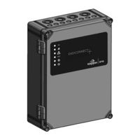
Kingspan EasyConnect+ Mounting Instructions (89 pages)
Brand:
Kingspan
| Category:
Measuring Instruments
| Size: 7 MB
Table of Contents
Deutsch
2
Table of Contents
2
1 Allgemeines und Sicherheit
4
2 Produktbeschreibung
6
Besondere Merkmale
6
3 Technische Daten
7
4 Übersicht der Grundplatine und Anschlussmöglichkeiten
10
5 Musterverkabelungsplan
11
6 Kabellängendiagramm
12
Formel Kabelquerschnittsermittlung
12
7 Montage
13
8 Elektrische Anschlüsse
14
Anschluss Netz 230 V AC
14
Anschluss Antriebe 24 V DC
14
Anschluss nicht Kompatibler Antriebe, wie Z.b. Linearantriebe mit Einfacher Lastabschaltung, mit
15
Trennmodul ESM (nur bei 2-Draht Leitungsüberwachung)
15
Anschluss Haftmagnete 24 V DC
15
Anschluss RWA-Bedienstellen
16
Anschluss Automatische Melder
17
Anschluss Brandmeldeanlage (BMA)
18
Anschluss Lüftungstaster 24 V
19
Anschluss Externer Reset-Taster
20
Anschluss Wind-/ Regenmelder Typ WRM/2 24V oder Regenmelder Typ RM/2 24V
20
Anschluss 3 X Potentialfreie Relaisausgänge
21
Anschluss Separater Spannungsausgang 27 V DC / 4 a
21
9 Funktions-DIP-Schalter
22
10 Inbetriebnahme
24
11 LED Anzeigen
26
LED Anzeigen auf der Gehäusetür
26
LED Anzeigen auf der Hauptplatine
26
LED Anzeigen Antriebe Kanal 1 + 2
26
LED Anzeigen BMA Kanal 1 + 2
26
LED Anzeigen Automatische Melder Kanal 1 + 2
27
LED Anzeigen RWA-Taster Kanal 1 + 2
27
LED Anzeigen Lüftungstaster Kanal 1 + 2
27
LED Anzeigen Wind-/ Regenmeldung
27
12 Störungsmeldung / Störungsursache
28
Störungsmeldung Türanzeige (Gelb)
28
Zustands- und Störungsmeldung auf der 2 X 7-Segment-Anzeige der Hauptplatine
28
13 Maßzeichnung
29
14 Wartung
30
Allgemeine Informationen zu Wartungsarbeiten
30
Wartungsarbeiten
30
Funktionstest der Leds in der Gehäusetür
31
15 Konfigurationssoftware E Asyconnect
32
Allgemeine Informationen zur Konfigurationssoftware Easyconnect
32
Systemvoraussetzungen
32
Oberfläche Info
32
Verbinden mit der Steuerzentrale Easyconnect, Starten der Software und Automatisches Starten der Oberfläche Info
32
Eingabe Lizenz Schlüssel
33
Konfigurationsoberfläche Rwa
33
Konfigurationsoberfläche Lüftung
35
Konfigurationsoberfläche Funktionswahl
36
Konfigurationsoberfläche Experten
37
Konfigurationsoberfläche Wartung
38
16 Vernetzung Mehrerer Easyconnect
39
Netzwerktopologien Leitungsart und Leitungslängen L
39
Anschluss an Netzwerkplatine
40
Inbetriebnahme Mehrerer Vernetzter Easyconnect 20A Steuerzentralen
40
Hinzufügen / Entfernen von Steuerzentralen aus einem Vorhandenen Netzwerk
41
Vernetzungsbeispiele und Einstellung der Bereichs DIP-Schalter
41
Abschalten des Netzwerks
44
17 Service
44
Bedienung des Easyconnect Reset-Taster
44
Rücksetzen auf Werkseinstellungen
44
Reset RWA- und BMA-Auslösung
44
Adresse Anzeigen / Ändern
44
Anzeigen der Firmware-Version
45
18 Symbolerklärung
45
English
46
1 General Information and Safety Instructions
48
2 Product Description
50
Special Features
50
3 Technical Data
51
4 Overview of the Motherboard and Connection Possibilities
54
Sample Wiring Diagram
55
6 Cable Lengths Diagram
56
Formula for Calculating the Cable Cross-Section
56
7 Installation
57
8 Electrical Connections
58
Connection to 230 V AC Mains
58
Connection to 24 V DC Drives
58
Connection of Non-Compatible Drives, E.g. Linear Drives with Simple Load Disconnection, with ESM Disconnection Module (Only with 2-Wire Line Monitoring)
59
Connection to 24 V DC Magnetic Clamps
59
Connection to SHE Manual Call Points
60
Connection to Automatic Detectors
61
Connection To Fire Alarm System (Fas)
62
Connection to 24 V DC Vent Switch
63
Connection of External Reset Buttons
64
Connection of 3 X Floating Relay Outputs
65
Connection of Separate 27 V DC / 4 a Voltage Output
65
9 DIP Switch Functions
66
10 Commissioning
68
11 LED Displays
70
LED Displays on the Housing Door
70
LED Displays on the Motherboard
70
LED Displays for Drive Channels 1 + 2
70
LED Displays for FAS Channels 1 + 2
70
LED Displays for Automatic Detector Channels 1 + 2
71
LED Displays for SHE Buttons Channel 1 + 2
71
LED Displays for Ventilation Push Button Channels 1 + 2
71
LED Displays for Wind/Rain Sensor
71
12 Error Messages / Cause of Fault
72
Error Message on Door Display (Yellow)
72
Status and Error Message on the 2 X 7-Segment Display of the Motherboard
72
13 Dimensional Drawing
73
14 Maintenance
74
General Information on Maintenance Work
74
Maintenance Work
74
Function Test of the Leds in the Housing Door
75
15 Configuration Software Easyconnect
76
General Information about the Easyconnect Configuration Software
76
System Requirements
76
Connecting with the Easyconnect Control Panel, Starting the Software and Automatic Starting the Info Interface
76
Info Interface
76
Input License Key
77
She Configuration Interface
77
Ventilation Configuration Interface
79
Function Selection Configuration Interface
80
Special Configuration Interface
81
Maintenance Configuration Interface
82
16 Networking of Several Easyconnect
83
Network Topologies Line Type and Lengths L
83
Connection to Network Board
84
Commissioning of Several Networked Easyconnect+ Control Panels
84
Adding / Removing Control Panels on an Existing Network
85
Networking Examples and Setting the Area DIP Switches
85
Switch Off The Network
88
17 Service
88
Operating the Easyconnect Reset Button
88
Reset to Factory Settings
88
Reset SHE- and FAS Activating
88
Show / Change Address
88
Displaying The Firmware Version
89
18 Explanation of Symbols
89
Advertisement
Advertisement
Related Products
Kingspan 13386201006
Kingspan TMS300 MULTI-TANK CS
Kingspan WATCHMAN Flo
Kingspan Categories
Water Heater
Water System
Measuring Instruments
Control Panel
Industrial Equipment
More Kingspan Manuals
Login
Sign In
OR
Sign in with Facebook
Sign in with Google
Upload manual
Upload from disk
Upload from URL