
Kinco CD420 Manuals
Manuals and User Guides for Kinco CD420. We have 2 Kinco CD420 manuals available for free PDF download: Manual, User Manual

Advertisement
Kinco CD420 User Manual (108 pages)
Brand: Kinco
|
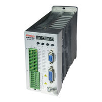
Category: Servo Drives
|
Size: 3 MB