Sign In
Upload
Manuals
Brands
Keysight Technologies Manuals
Test Equipment
PNA-L N5239B
Keysight Technologies PNA-L N5239B Manuals
Manuals and User Guides for Keysight Technologies PNA-L N5239B. We have
2
Keysight Technologies PNA-L N5239B manuals available for free PDF download: Service Manual, Installation Manual
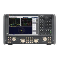
Keysight Technologies PNA-L N5239B Service Manual (282 pages)
2-Port and 4-Port PNA-L RF and Microwave Network Analyzers 300 kHz - 13.5/20/8.5 GHz
Brand:
Keysight Technologies
| Category:
Measuring Instruments
| Size: 8 MB
Table of Contents
Safety Notices
2
Table of Contents
3
Safety and Regulatory Information
11
Information in this Chapter
11
Chapter One At-A-Glance
11
Safety Symbols
12
General Safety Considerations
13
Safety Earth Ground
13
Before Applying Power
13
Servicing
15
Electrostatic Discharge Protection
17
Regulatory Information
19
Instrument Markings
19
General Product Information
21
Information in this Chapter
21
Chapter Two At-A-Glance
21
Maintenance
22
Physical Maintenance
22
Electrical Maintenance
22
Analyzer Options, Accessories, and Upgrades Available
23
Required Service Test Equipment
24
Keysight Support, Services, and Assistance
27
Service and Support Options
27
Contacting Keysight
27
Shipping Your Analyzer to Keysight for Service or Repair
27
Tests and Adjustments
29
Information in this Chapter
29
Conventions Used for Hardkeys, Softkeys, and Menu Items
29
Chapter Three At-A-Glance
29
Before You Begin
32
Verify the Operating Environment
32
Protect against Electrostatic Discharge (ESD)
32
Allow the Analyzer to Warm up
33
Review the Principles of Connector Care
33
About System Verification and Performance Tests
35
System Specifications
35
Instrument Specifications
35
System Verification Procedure
36
Performance Tests
36
Certificate of Calibration
36
ANSI/NCSL Z540.3-2006 and ISO/IEC 17025 Verification
38
Non-Standards Compliant Verification
39
Preliminary Checks
40
The Test Port Cable Checks
40
The Operator's Check
40
System Verification
49
What the System Verification Verifies
49
Measurement Uncertainty
49
Measurement Traceability
50
Performing System Verification
51
Performance Tests
59
Source Power Accuracy Test
59
Source Maximum Power Output Test
60
Source Power Linearity Test
61
Frequency Accuracy Test
62
Trace Noise Test
62
Receiver Compression Test
63
Noise Floor Test
65
Calibration Coefficients Test
66
Dynamic Accuracy Test
67
Adjustments
69
Touchscreen Adjustment and Verification
69
10 Mhz Frequency Reference Adjustment
70
Synthesizer Bandwidth Adjustment
71
Source Adjustment
71
IF Gain Adjustment
72
Receiver Adjustment
72
EE Default Adjustment
75
IF Response Adjustment (Available Only with Option S93093/4A and or S93900/1/2/4/5/7A Installed)
75
Troubleshooting
77
Information in this Chapter
77
Chapter Four At-A-Glance
78
Conventions Used for Hardkeys, Softkeys, and Menu Items
78
Operating the Analyzer with Covers Removed
79
Protect against Electrostatic Discharge (ESD)
80
Assembly Replacement Sequence
81
Getting Started with Troubleshooting
82
Check the Basics
82
Troubleshooting Organization
82
Power up Troubleshooting
84
Power Supply Check
85
Troubleshooting LCD Display Problems
91
Front Panel Troubleshooting
92
Front Panel Keypad and RPG Test
92
A3 Display Test
95
Checking the A2 USB Board
96
A1 Front Panel Interface Board
97
Rear Panel Troubleshooting
99
Checking the USB Ports
99
Checking the CONTROLLER Port
99
LAN Troubleshooting
100
Measurement System Troubleshooting
106
Before You Begin-Consider: Where Do You See a Problem
106
Verifying the A, B, C, D, and R Traces (Standard S-Parameter Mode)
107
Where to Begin Troubleshooting
110
Checking the Source Group
112
Checking the Signal Separation Group
116
Checking the Receiver Group
118
Instrument Block Diagrams Sheet 1
121
Microwave PNA, N523Xb, 2-Port Model
121
Instrument Block Diagrams Sheet 2
123
Microwave PNA, N523Xb, 4-Port Model
123
Theory of Operation
125
Information in this Chapter
125
Chapter Five At-A-Glance
125
Network Analyzer System Operation
126
Functional Groups of the Network Analyzer
127
Synthesized Source Group Operation
130
Basic Operation
130
A4 and A10 13.5 Ghz Synthesizer Boards
133
A20 Massquad (4-Port Models)
134
A21 MASSY (2-Port Models)
134
A7 Frequency Reference Board
134
A19 Test Set Motherboard
135
Signal Separation Group Operation
139
Configurable Test Set
139
A25 and A28 Test Port Couplers
140
A29-A30 60 Db Step Attenuators
142
Receiver Group Operation
143
A24 Mixer Brick
143
A9 SPAM Board (Analog Description)
143
Digital Processing and Digital Control Group Operation
146
Front Panel Subgroup
148
Data Acquisition and Processing Subgroup
149
Power Supply Group Operation
151
Replaceable Parts
153
Information in this Chapter
153
Chapter Six At-A-Glance
153
Ordering Information
154
Assembly Replacement Sequence
155
Rebuilt-Exchange Assemblies
156
Replaceable Parts Listings
158
Front Panel Assembly, Front Side, All Options
162
Front Panel Assembly, Back Side, All Options
164
Top Assemblies, All Models
167
Top Cables, All Models
169
Bottom Assemblies, N523Xa, Option 200
171
Bottom Cables, N523Xa, Option 200
173
Bottom Ribbon Cables, N523Xa, Option 200
175
Bottom Assemblies, N523Xa, Option 216
177
Bottom Cables, N523Xa, Option 216
179
Bottom Ribbon Cables, N523Xa, Option 216
181
Bottom Assemblies, N5231B and N5232B, Option 400
183
Bottom Cables, N5231B and N5232B, Option 400
185
Bottom Ribbon Cables, N5231B and N5232B, Option 400
187
Bottom Assemblies, N5231B and N5232B, Option 416
189
Bottom Cables, N5231B and N5232B, Option 416
191
Bottom Ribbon Cables, N5231B and N5232B, Option 416
193
Bottom Hardware and Miscellaneous Parts
195
Internal Hardware and Miscellaneous Parts, All Models
197
External Hardware and Miscellaneous Parts, All Models
199
Rear Panel Assembly, All Models
201
Miscellaneous Part Numbers
202
Repair and Replacement Procedures
205
Information in this Chapter
205
Chapter Seven At-A-Glance
205
Personal Safety Warnings
206
Electrostatic Discharge (ESD) Protection
207
Assembly Replacement Sequence
208
Removal and Replacement Procedures
209
Removing the Covers
211
Removing and Replacing the Front Panel Assembly
213
Removing and Replacing the A1-A3 and Other Front Panel Subassemblies
215
N/A Front Panel Assembly
215
Removing and Replacing the A4, A7, A9, and A10 Boards
223
Removing and Replacing the A14 System Motherboard
225
System Motherboard
225
A15 Midplane Board
225
Power Supply Assembly
225
CPU Board
225
GPIB Board
225
Removing and Replacing the A15 Midplane Board
228
Removing and Replacing the A16 Power Supply Assembly
230
Removing and Replacing the A17 CPU Board
231
Removing and Replacing the A18 GPIB Board
232
Removing and Replacing the A19 Test Set Motherboard
233
Removing and Replacing the A20 Massquad
234
Massquad (4-Port Models Only)
234
Removing and Replacing the A21 MASSY
235
A21 MASSY (2-Port Models Only)
235
Removing and Replacing the A24 Mixer Brick (Quintbrick)
236
A24 Mixer Brick (Quintbrick)
236
Removing and Replacing the A25-A28 Test Port Bridge Couplers
237
Removing and Replacing the A29 and A30 60 Db Source Step Attenuators
238
Removing and Replacing the A51 Solid State Drive (SSD)
239
Removing and Replacing the Rear Panel
240
Removing and Replacing the Front Panel LED Boards
241
Removing and Replacing the Fans
243
Removing and Replacing the Lithium Battery
245
Post-Repair Procedures
247
General Purpose Maintenance Procedures
251
Information in this Chapter
251
Chapter Eight At-A-Glance
251
Error Terms
252
Using Error Terms as a Diagnostic Tool
252
Performing Measurement Calibration
253
Using Flowgraphs to Identify Error Terms
253
Accessing Error Terms
256
Error Term Data
258
Keysight License Manager
262
Accessing the Keysight License Manager
262
Enabling or Removing Options
263
Repairing and Recovering Option Data
263
Installing or Changing a Serial Number
264
Firmware Upgrades
265
How to Check the Current Firmware Version
265
Downloading from the Internet
265
Operating System Recovery
266
Recovering from Hard Disk Drive Problems
266
Correction Constants
266
Storing Correction Constants
266
Advertisement
Keysight Technologies PNA-L N5239B Installation Manual (12 pages)
Windows 10 Operating System Upgrade Kit
Brand:
Keysight Technologies
| Category:
Test Equipment
| Size: 0 MB
Table of Contents
Safety Notices
2
Description of the Upgrade
3
Getting Assistance from Keysight
3
Contacting Keysight
3
Getting Prepared
4
Items Included in the Upgrade Kit
6
Before You Install this Upgrade Kit
6
Upgrade Procedure
8
Advertisement
Related Products
Keysight Technologies PNA-L N5231
Keysight Technologies PNA-L N5232
Keysight Technologies PNA-L N5234
Keysight Technologies PNA-L N5235
Keysight Technologies N5280A
Keysight Technologies PNA-X N524xB
Keysight Technologies PNA-X N5264B
Keysight Technologies N5225-60105
Keysight Technologies N5225AU-401
Keysight Technologies N5222-60124
Keysight Technologies Categories
Measuring Instruments
Test Equipment
Control Unit
Portable Generator
Power Supply
More Keysight Technologies Manuals
Login
Sign In
OR
Sign in with Facebook
Sign in with Google
Upload manual
Upload from disk
Upload from URL