Sign In
Upload
Manuals
Brands
Keysight Technologies Manuals
Power Supply
E364 A Series
Keysight Technologies E364 A Series Manuals
Manuals and User Guides for Keysight Technologies E364 A Series. We have
1
Keysight Technologies E364 A Series manual available for free PDF download: User's And Service Manual
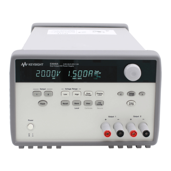
Keysight Technologies E364 A Series User's And Service Manual (255 pages)
Dual Output DC Power Supplies
Brand:
Keysight Technologies
| Category:
Power Supply
| Size: 7.25 MB
Table of Contents
Safety Symbols
4
Safety Considerations
5
Environmental Conditions
7
Regulatory Information
8
Safety Compliance
8
EMC Compliance
8
Regulatory Markings
9
Waste Electrical and Electronic Equipment (WEEE) Directive
10
Product Category
10
Sales and Technical Support
10
Table of Contents
12
Getting Started
24
Introduction
25
Figure 1-1 Rear Output Terminals
28
Standard Shipped Items
29
Options
29
Table 1-1 E364Xa Options
29
Accessories
30
Table 1-2 E364Xa Accessories
30
Preparing the Power Supply
31
Checking the Power Supply
31
Connecting Power to the Power Supply
32
Table 1-3 E364Xa Power-Line Fuse
32
Checking the Output
33
Converting Line Voltage
35
Figure 1-2 Line Voltage Selector (Set for 115 Vac)
35
Rack-Mounting the Power Supply
38
Product at a Glance
40
Front Panel
40
Figure 1-3 Front Panel
40
Table 1-4 Front Panel Overview
40
Figure 1-4 Voltage and Current Limit Settings
42
Rear Panel
43
Figure 1-5 Rear Panel
43
Table 1-5 Rear Panel Overview
43
Display Annunciators
44
Figure 1-6 Display Annunciators
44
Table 1-6 Display Annunciators Overview
44
Output Connections
46
Current Ratings
46
Table 1-7 Wire Rating
46
Voltage Drops
47
Load Consideration
47
Remote Voltage Sensing Connections
48
Figure 1-7 Remote Voltage Sensing Connections
49
Multiple Loads
51
Operating the Power Supply
52
Cooling
52
Bench Operation
52
Cleaning
52
Operation and Features
54
Overview
55
Constant Voltage Operation
56
Front Panel Operation
56
Remote Interface Operation
58
Constant Current Operation
59
Front Panel Operation
59
Remote Interface Operation
61
Track Mode Operation
62
Front Panel Operation
62
Remote Interface Operation
63
View Mode Operation
64
Changing the Display Mode
64
Viewing the Errors
65
Viewing the Firmware Version
65
Viewing the Calibration String
66
Configuring the Remote Interface
67
GPIB Configuration
67
RS-232 Configuration
68
Storing and Recalling Operating States
69
Front Panel Operation
69
Remote Interface Operation
71
Programming the Overvoltage Protection
72
Front Panel Operation
72
Remote Interface Operation
74
Figure 2-1 Recommended Protection Circuit for Battery Charging
75
Disabling the Output
76
Front Panel Operation
76
Remote Interface Operation
76
Disconnecting the Output Using an External Relay
77
System-Related Operations
78
State Storage
78
Self-Test
79
Error Conditions
80
Firmware Revision Query
80
SCPI Language Version
81
GPIB Interface Reference
82
RS-232 Interface Reference
83
RS-232 Configuration Overview
83
RS-232 Data Frame Format
83
Connection to a Computer or Terminal
84
Figure 2-2 DB-9 Serial Connection
84
RS-232 Trouble Shooting
85
Figure 2-3 DB-25 Serial Connection
85
Calibration
86
Calibration Security
86
To Unsecure for Calibration
87
Table 2-1 Factory-Setting Security Codes
87
To Secure against Calibration
88
To Change the Security Code
90
Calibration Count
91
Calibration Message
91
SCPI Command Summary
95
Remote Interface Reference
95
Output Setting and Measurement Commands
96
Triggering Commands
97
System-Related Commands
97
State Storage Commands
98
Calibration Commands
98
Interface Configuration Commands
98
Status Reporting Commands
99
IEEE-488.2 Common Commands
100
Introduction to the SCPI Language
101
Command Format Used in this Manual
102
Command Separators
103
Using the MIN and MAX Parameters
103
Querying Parameter Settings
104
SCPI Command Terminators
104
IEEE-488.2 Common Commands
105
SCPI Parameter Types
105
Simplified Programming Overview
107
Using the Apply Command
107
Using the Low-Level Commands
107
Reading a Query Response
108
Selecting a Trigger Source
108
Power Supply Programming Ranges
109
Table 3-1 Keysight E364Xa Programming Ranges
109
Using the Apply Command
110
Output Setting and Operation Commands
111
Triggering Commands
118
Trigger Source Choices
118
Triggering Commands
120
System-Related Commands
121
Table 3-2 Power Supply State
124
State Storage Commands
125
Calibration Commands
127
Calibration Example
129
Interface Configuration Commands
131
SCPI Status Registers
132
What Is an Event Register
132
What Is an Enable Register
132
What Is a Multiple Logical Output
133
Figure 3-1 Multiple Logical Output
133
SCPI Status System
134
Figure 3-2 SCPI Status System
134
Questionable Status Register
135
Table 3-3 Bit Definitions - Questionable Status Register
135
Standard Event Register
137
Table 3-4 Bit Definitions - Standard Event Register
137
Status Byte Register
138
Using Service Request (SRQ) and Serial POLL
139
Table 3-5 Bit-Definitions - Status Byte Summary Register
139
Using *STB? to Read the Status Byte
140
Using the Message Available Bit (MAV)
140
To Interrupt Your Bus Controller Using SRQ
141
Determining When a Command Sequence Is Completed
141
Using *OPC to Signal When Data Is in the Output Buffer
142
Status Reporting Commands
143
Halting an Output in Progress
147
SCPI Conformance Information
148
SCPI Confirmed Commands
148
Device Specific Commands
150
IEEE-488 Conformance Information
151
Error Messages
152
Overview
153
Front Panel Operation
153
Remote Interface Operation
154
Execution Error Messages
155
Table 4-1 Execution Error Messages
155
Self-Test Error Messages
162
Table 4-2 Self-Test Error Messages
162
Calibration Error Messages
165
Table 4-3 Calibration Error Messages
165
Application Programs
168
Overview
169
Example Program for C and C
170
Diode.C
170
Example Program for Excel 97
174
Figure 5-1 Example Program Result
174
Declaration for Windows 3.1
179
Declaration for Windows 9.5/NT 4.0
179
Tutorial
180
Overview of the Power Supply Operation
181
Figure 6-1 Diagram of a Simple Series Power Supply
181
Figure 6-2 Block Diagram of the Power Supply Showing the Remote Interface Isolation
182
Output Characteristics
183
Figure 6-3 Ideal Constant Voltage Power Supply
183
Figure 6-4 Ideal Constant Current Power Supply
183
Figure 6-5 Output Characteristics
184
Unregulated State
185
Unwanted Signals
185
Figure 6-6 Simplified Diagram of Common Mode and Normal Mode Sources of Noise
186
Extending the Voltage and Current Range
187
Series Connections
187
Parallel Connections
187
Remote Programming
188
Figure 6-7 Speed of Response - Programming up (Full Load)
188
Figure 6-8 Speed of Response - Programming down
189
Characteristic and Specifications
191
Physical Characteristics
191
Figure 7-1 E364Xa Dimensions
191
Table 7-1 Physical Characteristics
191
Characteristic and
191
Environmental Characteristics
192
Figure 7-2 E364Xa Dimensions for Rack Mounting
192
Electrical Specifications
193
Table 7-2 Electrical Specifications
193
Supplemental Characteristics
195
Table 7-3 Supplemental Characteristics
195
Service and Maintenance
199
Overview
199
Operating Checklist
200
Types of Services Available
201
Standard Repair Service (Worldwide)
201
Repacking for Shipment
201
Electrostatic Discharge (ESD) Precautions
202
Surface Mount Repair
202
Replacing the Power-Line Fuse
202
Troubleshooting Hints
203
Unit Reports Errors 740 to 755
203
Unit Fails Self-Test
203
Bias Supplies Problems
203
Table 8-1 Bias Supplies Voltages
204
Table 8-2 Bias Supplies Voltages (Serial My53Xx6Xxx)
204
Self-Test Procedures
205
Power-On Self Test
205
Complete Self-Test
205
Table 8-3 Self-Test Error Messages
206
General Disassembly
207
Figure 8-1 General Disassembly
207
Recommended Test Equipment
208
Table 8-4 Recommended Test Equipment
208
Test Considerations
210
Operation Verification and Performance Tests
211
Operation Verification Tests
211
Performance Tests
211
Measurement Techniques
212
Common Test Setup
212
Figure 8-2 Performance Verification Test Setup
212
Current-Monitoring Resistor
213
General Measurement Techniques
213
Figure 8-3 Front or Rear Panel Terminal Connections
213
Electronic Load
214
Programming
214
Constant Voltage (CV) Verifications
215
Constant Voltage Test Setup
215
Voltage Programming and Readback Accuracy
215
Table 8-5 Verification Programming Values
215
CV Load Effect (Load Regulation)
217
CV Source Effect (Line Regulation)
218
CV PARD (Ripple and Noise)
219
Figure 8-4 Front/Rear Panel Terminal Connections for the Vrms Measurement
219
Load Transient Response Time
221
Figure 8-5 Transient Response Time
222
Constant Current (CC) Verification
223
Constant Current Test Setup
223
Current Programming and Readback Accuracy
223
CC Load Effect (Load Regulation)
225
CC Source Effect (Line Regulation)
226
CC PARD (Ripple and Noise)
227
Figure 8-6 CC PARD (Ripple and Noise) Connections
227
Common Mode Current Noise
229
Performance Test Record
230
Table 8-6 CV Performance Test Record
230
Table 8-7 CC Performance Test Record
231
Calibration Reference
232
Keysight Calibration Services
232
Calibration Interval
232
To Unsecure the Power Supply Without the Security Code
232
General Calibration or Adjustment Procedure
234
Table 8-8 Parameters for Calibration
235
Front Panel Voltage and Current Calibration
236
Calibration Record
240
Table 8-9 Calibration Record
240
Calibration Error Messages
242
Table 8-10 Calibration Error Messages
242
Component Locator Diagram
244
Component Locator Diagram for the Main Board Assembly - Top
244
Component Locator Diagram for the Main Board Assembly - Bottom
245
Component Locator Diagram for the Digital Board Assembly - Top
246
Component Locator Diagram for the Digital Board Assembly - Bottom
247
Component Locator Diagram for the Front Panel - Top
248
Component Locator Diagram for the Main Board Assembly - Top (Serial My53Xx6Xxx)
249
Component Locator Diagram for the Main Board Assembly - Bottom (Serial My53Xx6Xxx)
250
Component Locator Diagram for the Digital Board Assembly - Top (Serial My53Xx6Xxx)
251
Component Locator Diagram for the Digital Board Assembly - Bottom (Serial My53Xx6Xxx)
252
Component Locator Diagram for the Front Panel - Top (Serial My53Xx6Xxx)
253
Advertisement
Advertisement
Related Products
Keysight Technologies E3646A
Keysight Technologies E3648A
Keysight Technologies E3647A
Keysight Technologies E3649A
Keysight Technologies E364xA Series
Keysight Technologies E3642A
Keysight Technologies E3640A
Keysight Technologies E3641A
Keysight Technologies E3643A
Keysight Technologies E3645A
Keysight Technologies Categories
Measuring Instruments
Test Equipment
Control Unit
Portable Generator
Power Supply
More Keysight Technologies Manuals
Login
Sign In
OR
Sign in with Facebook
Sign in with Google
Upload manual
Upload from disk
Upload from URL