Sign In
Upload
Manuals
Brands
Keysight Manuals
Control Unit
N7565A
Keysight N7565A Manuals
Manuals and User Guides for Keysight N7565A. We have
1
Keysight N7565A manual available for free PDF download: User Manual
Keysight N7565A User Manual (97 pages)
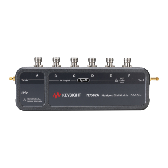
Multiport Electronic Calibration Module, DC to 9/20/26.5 GHz
Brand:
Keysight
| Category:
Control Unit
| Size: 2 MB
Table of Contents
Warranty
2
Certification
3
Safety Information
4
Safety Considerations
4
Safety Symbols
5
Regulatory Markings
6
South Korean Class a EMC Declaration
6
Sales and Technical Support
7
Table of Contents
9
List of Figures
11
List of Tables
13
General Information
15
Overview
16
Prerequisite Knowledge
16
Clarifying the Terminology of a Connector Interface
16
When to Calibrate
18
Models
18
Figure 1-1 Model N7562A Type-N Female
18
Options
19
Figure 1-2 Model N756Xa 3.5 MM Female
19
Table 1-1 N756Xa Modules
19
Table 1-2 N756Xa Options
20
Table 1-3 N756Xaep Options
21
Table 1-4 N756Xa Accessories Options
22
N756Xa Connection Restrictions
23
Figure 1-3 N756Xa Multiport Configuration Setup
23
Assembling Multiple N756Xa Modules for Multiport Configuration
24
Figure 1-4 N756Xa Configuration Setup
24
Figure 1-5 Installation of Mounting Bracket Assembly
25
Figure 1-6 Vertical Thru Port Connection
25
Figure 1-7 Installation of Semi-Rigid Cable Guard Assembly
26
Figure 1-8 Installation of Stand Plate
26
Figure 1-9 Connection between Three or more N756Xa Modules
27
Figure 1-10 Installation of Bracket Horizontal Assembly
28
Figure 1-11 Horizontal Thru Port Connection
28
Compatible Network Analyzers
29
Table 1-5 N756Xa Compatible Network Analyzers
29
Service and Recertification
30
Contacting Keysight
30
Preparing Ecal for Use
34
Inspecting the Ecal Kit
34
Figure 2-12 Ecal Model and Serial Numbers on the Backside of the Ecal Module
34
Record the Serial Number
35
Equipment Required but Not Supplied
35
Kit Contents
36
Table 2-6 N756Xaep Kit Contents
36
Table 2-7 N756Xa Kit Contents
36
Operating and Safety Precautions
37
ESD Damage
37
Connector Care
37
Input Power Level
38
Table 2-8 Input Power Limits
38
Operating Temperature
38
Using Ecal Software
40
Using the Ecal Software
40
System Requirements
40
Software Installation Overview
41
How to Start the SFP Launcher
42
Figure 3-13 Connect to Instrument Dialog
42
Figure 3-14 Connect to Instrument Dialog
43
Figure 3-15 Save Instrument Connection Dialog
44
Using N756Xa Series Ecal Modules for Calibration
45
Figure 3-16 Ecal Selection
46
Figure 3-17 Calibration Wizard
46
Figure 3-18 Electronic Calibration: Advanced Settings
47
Operating Ecal Module
50
Setting up a Calibration
50
Table 4-9 N756Xa Status LED Operation
50
Supported Calibration Methods
51
Figure 4-19 Non-Insertable Ecal Module
51
Adapter Removal
52
Validating a Calibration
53
Ecal Troubleshooting
55
Table 4-10 N756Xa Status LED States
55
Known Issues
56
Figure 4-20 Ecal Module Not Found Dialog
56
Figure 4-21 Error: Frequency Range Dialog
56
Use, Maintenance, and Care of the Devices
57
Electrostatic Discharge
58
Figure 5-22 ESD Protection Using Mat, Wrist Strap, and Grounded Power Cord
58
Visual Inspection
59
Look for Obvious Defects and Damage First
59
Inspect the Mating Plane Surfaces
59
Inspect Female Connectors
60
Figure 5-23 Type-N Connector Pin Depth and Mating Surfaces
60
Cleaning Connectors
61
Gaging Connectors
63
Connector Gage Accuracy
63
Figure 5-24 Typical Gage: 3.5 MM Connectors
65
Figure 5-25 Typical Gage: Type-N Connectors
66
Gaging Procedures
67
Making Connections
69
Final Connection Using a Torque Wrench
69
Figure 5-26 Wrench Positions
70
Figure 5-27 Using the Torque Wrench
71
Table 5-11 Ecal Module Torque Wrench Information
72
Handling and Storage
73
Ecal Kit Storage Box (Option 150)
74
Table 5-12 N756Xa Storage Box Part Number
74
Figure 5-28 Ecal Kit Fiberboard Storage Box
75
Specifications and Characteristics
77
Specifications: Terminology and Definitions
78
Table 6-13 Specifications and Characteristics Terminology
78
Environmental Specifications
79
Table 6-14 Environmental Specifications
79
Electrical and Characteristic Specification
80
Mechanical Characteristics
80
Pin Depth
80
Figure 6-29 Pin Depth for 3.5 MM Connectors
81
Figure 6-30 Pin Depth for Type-N Connectors
82
Typical Pin Depth Values
83
Table 6-15 Type-N 50 Connector Pin Depth Characteristics
83
Table 6-16 3.5 MM Connector Pin Depth Characteristics
83
Supplemental Mechanical Characteristics
84
Figure 6-31 N7562A Modules - Type-N Female
84
Table 6-17 N756Xa Series Mechanical Characteristics
84
Figure 6-32 N756Xa Modules - 3.5 MM Female
85
Measurement Uncertainty Calculator
86
Replaceable Parts
87
Description of this Chapter
88
Type-N (50 Ohm) Modules and Accessories
89
Table 7-18 Type-N Modules and Accessories
89
3.5 MM Modules and Accessories
93
Table 7-19 3.5 MM Modules and Accessories
93
Advertisement
Advertisement
Related Products
Keysight N7550A
Keysight N7551A
Keysight N7552
Keysight N7553A
Keysight N7554A
Keysight N7555A
Keysight N7552A
Keysight N7562A
Keysight N7564A
Keysight N5262BR12-001
Keysight Categories
Measuring Instruments
Test Equipment
Multimeter
Portable Generator
Power Supply
More Keysight Manuals
Login
Sign In
OR
Sign in with Facebook
Sign in with Google
Upload manual
Upload from disk
Upload from URL