Sign In
Upload
Manuals
Brands
Keysight Manuals
Chassis
M9502A
Keysight M9502A Manuals
Manuals and User Guides for Keysight M9502A. We have
1
Keysight M9502A manual available for free PDF download: User Manual
Keysight M9502A User Manual (142 pages)
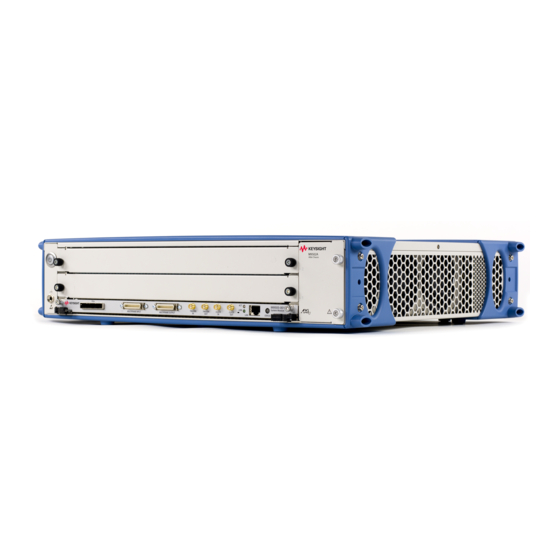
2-Slot and 5-Slot AXIe Chassis
Brand:
Keysight
| Category:
Chassis
| Size: 18 MB
Table of Contents
Table of Contents
7
Introduction
11
Axie Chassis Description
12
M9502A 2-Slot Axie Chassis at a Glance
14
M9505A 5-Slot Axie Chassis at a Glance
16
Axie Embedded System Module (ESM)
18
Axie Embedded System Module (ESM) Option U20 with USB
19
Axie Instrument Modules
20
ESD Precautions
21
Power-Up and Power-Down
22
Circuit Breaker
22
ON/STANDBY Switch
22
Power Modes
22
To Power up the Chassis
23
To Power down the Chassis
25
Chassis Firmware, IVI Driver, and IO Libraries Matrix
26
Safety-Related Specifications
27
Regulatory
27
Operating Conditions
27
Chassis Weight
28
AC Power Supply Requirements
28
Chassis Power Dissipation
28
DC Power Supply Output
28
Related Documentation
29
Product Warranty
29
Chassis Installation
32
Planning the Installation
32
Basic Chassis Verification
32
Complete Installation
32
Once Chassis Are in Place
32
Installing Modules
33
To Remove a Filler Panel Module
34
To Install a Module
34
To Remove a Module
38
Mounting the Chassis
39
Environmental and Power Considerations
39
Rackmounting the Chassis
39
To Remove the Carry Handle and Bumpers from the M9502A
40
To Remove the Carry Handles and Bumpers from the M9505A
41
Reinstalling the Bumpers and Carry Handles
43
Setting up a Host PC
44
To Install Module Soft Front Panel and Device Drivers
44
Verifying Operation with Modules Installed
45
Using the M9536A Embedded Controller LAN Ports
46
Recommendations
47
Using an External Controller
51
Using Multiple Chassis
52
How Does a Multiple Chassis System Differ from a Multiframe System
52
Navigating the Web Interface
53
Launching the Web Interface
53
Home Page
54
Menu
55
LAN Configuration Page
56
Module Configuration Page
57
ESM Pcie Upstream Connection Settings
58
New Configuration
58
E-Keying
59
Trigger Routing Page
61
Chassis Health Page
63
Configure Fan Control
64
Example of Chassis Fan Speed
66
Axie Chassis Version Information and Fan Speed
67
Using the Soft Front Panel
69
Starting the Soft Front Panel
70
SFP Screens
71
Monitor Screen
71
Configure Trigger Routing
71
Features and Functions
75
Chassis Block Diagram
76
Shelf Management Functions
78
To Monitor Fans
78
Current Speed Level
80
Dynamic Minimum Fan Level
80
Adjust Current Speed Level and Dynamic Minimum Fan Level
80
To Control Fan Speed
80
To Monitor Chassis Temperature
81
To Monitor Module Health
81
Pcie and LAN Switching (Data Transfer)
83
Data Channels Explained
83
Implementing Fabric 2
84
Maximizing Data Upload Speeds
84
Pcie, LAN or both
84
Chassis Synchronization and Triggering
85
Synchronization
86
Available Clocks
86
Selecting a Clock Bus Source
87
Using the Clocks
87
Triggering
88
Trigger Resources
89
Crosspoint Switch
90
Trig
92
Strig
93
Sync
94
Trigger out
96
Multiframe Flags
96
Multiframe SYNC
97
Multiframe Operation
99
Shared Features
99
Interconnection
100
To Connect a Multiframe Chassis
101
LVDS Local Bus
102
Electronic Keying (E-Keying)
102
E-Keying Process
104
For Module Developers
105
Module Types
106
ATCA and Axie Requirements
107
Overview
107
ATCA Requirements and Exceptions for Axie 1.0
107
Axie Extensions to Advancedtca
109
Chassis Backplane Connections
110
M9502A Backplane
110
M9505A Backplane
111
Zone 1 Connector Layout
112
Zone 1 Connector Usage
112
Zone 1 Pin Assignments
113
Zone 2 Connector Layout
114
Zone 2 Connector Usage
115
Zone 2 Pin Assignments
116
Troubleshooting and Service
119
Updating the Chassis Firmware
120
Revision String Numbering Format
120
Troubleshooting
121
Overview
121
Normal Chassis Operating Behavior
121
Chassis Hardware Troubleshooting
123
Chassis Fans
123
Power Supply Unit (PSU)
124
Embedded System Module (ESM)
124
User-Replaceable Parts
127
To Replace the Power Supply Unit
128
To Remove the PSU from the M9502A
128
To Remove the PSU from the M9505A
130
To Replace the Fan Tray
134
To Replace the Embedded System Module
134
Glossary
135
Advertisement
Advertisement
Related Products
Keysight M9506A
Keysight M9505A
Keysight M9514A
Keysight M9018A
Keysight PXIe M9018B
Keysight PXIe M9019A
Keysight PXIe M9010A
Keysight M9046A
Keysight M9521A
Keysight M9536A
Keysight Categories
Measuring Instruments
Test Equipment
Multimeter
Portable Generator
Power Supply
More Keysight Manuals
Login
Sign In
OR
Sign in with Facebook
Sign in with Google
Upload manual
Upload from disk
Upload from URL