Sign In
Upload
Manuals
Brands
Keysight Manuals
Test Equipment
InfiniiVision HD300MSO-100
Keysight InfiniiVision HD300MSO-100 Manuals
Manuals and User Guides for Keysight InfiniiVision HD300MSO-100. We have
1
Keysight InfiniiVision HD300MSO-100 manual available for free PDF download: User Manual
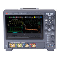
Keysight InfiniiVision HD300MSO-100 User Manual (368 pages)
Brand:
Keysight
| Category:
Test Equipment
| Size: 7 MB
Table of Contents
Print History
2
Warranty
2
Safety Notices
2
Infiniivision HD3-Series Oscilloscopes-At a Glance
3
In this Guide
5
Table of Contents
7
Getting Started
19
Inspect the Package Contents
19
Learn the Front Panel Inputs and Outputs
21
Learn the Back Panel Inputs and Outputs
22
Tilt the Oscilloscope for Easy Viewing
24
Power-On the Oscilloscope
25
Select the User Interface Language
26
Connect Probes to the Oscilloscope
26
Maximum Input Voltage at Analog Inputs
26
Do Not Float the Oscilloscope Chassis
26
Input a Waveform
27
Recall the Default Oscilloscope Setup
27
Use Autoscale
28
How Autoscale Works
28
Compensate Passive Probes
29
Learn the Front Panel Keys and Knobs
30
Front Panel Overlays for Different Languages
34
Using the Touchscreen User Interface
35
Access Features from the Menu
36
View and Change Settings with Badges
36
Quick-Select Waveforms to Display
37
Lay out Waveform Grids
37
View Waveforms in a Grid
39
Drag Markers
40
Customize the Favorites Menu
40
View Logged Messages
40
Select Draw Box or Drag Waveforms Mode
40
View Results
42
Enter Names Using Alpha-Numeric Keypad Dialogs
42
Use a USB Mouse And/Or Keyboard for Touchscreen Controls
42
Access the Built-In Online Help
43
Horizontal Controls
45
To Adjust the Horizontal Scale (Time/DIV)
46
To Adjust the Horizontal Delay (Position)
47
Panning and Zooming Single or Stopped Acquisitions
48
To Display the Zoomed Time Base
48
To Change the Horizontal Scale Coarse/Fine Adjustment Setting
50
To Position the Time Reference (Left, Center, Right, Custom)
50
Searching for Events
51
To Set up Searches
51
To Copy Search Setups
52
Navigating the Time Base
52
To Navigate Time
52
To Navigate Search Events
53
To Navigate Segments
53
Vertical Controls
55
To Turn Waveforms on or off
56
To Adjust the Vertical Scale
57
To Adjust the Vertical Position
57
To Specify Channel Coupling
57
To Specify Channel Input Impedance
58
To Specify Bandwidth Limiting
59
To Change the Vertical Scale Knob's Coarse/Fine Adjustment Setting
59
To Invert a Channel Waveform
60
Setting Analog Channel Probe Options
60
To Specify the Channel Units
61
To Specify the Probe Attenuation
61
To Specify the Probe Skew
62
To Calibrate a Probe
62
To Specify the Channel External Scaling
63
FFT Spectral Analysis
65
Searching for FFT Peaks
70
FFT Spectral Analysis
70
FFT Measurement Hints
71
FFT Units
72
FFT DC Value
72
FFT Aliasing
72
FFT Spectral Leakage
73
Math Waveforms
75
To Display Math Waveforms
75
Units for Math Waveforms
78
Arithmetic Math Functions
78
Add or Subtract
79
Multiply or Divide
79
Transforms Math Functions
80
Absolute Value
81
Ax + B
81
Base 10 Exponential
82
Common Logarithm
83
Differentiate
83
Exponential
84
Integrate
84
Natural Logarithm
86
Square Root
87
Square
88
FFT Math Functions
88
FFT Magnitude, FFT Phase
88
Filters Math Functions
90
Averaged Value
90
Band Pass Filter
91
Envelope
91
High Pass and Low Pass Filter
92
Smoothing
92
Visualizations Math Functions
93
Magnify
93
Max/Min Hold
94
Maximum/Minimum
94
Measurement Trend
94
The Analysis Record and Waveform Math
95
Reference Waveforms
99
To Save a Waveform to a Reference Waveform Location
99
To Display a Reference Waveform
100
To Scale and Position Reference Waveforms
100
To Adjust Reference Waveform Skew
101
To Display Reference Waveform Summary Information
101
To Save/Recall Reference Waveform Files To/From a USB Storage Device
101
To Connect the Digital Probes to the Device under Test
103
Digital Channels
104
Probe Cable for Digital Channels
104
Digital Channels
105
Acquiring Waveforms Using the Digital Channels
106
To Display Digital Channels Using Autoscale
106
Interpreting the Digital Waveform Display
107
To Change the Displayed Size of the Digital Channels
108
To Switch a Single Channel on or off
109
To Switch Multiple Digital Channels on or off
109
To Reposition a Digital Channel
109
To Change the Logic Threshold for Digital Channels
110
To Display Digital Channels as a Bus
110
Digital Channel Signal Fidelity: Probe Impedance and Grounding
113
Input Impedance
113
Probe Grounding
115
Best Probing Practices
116
Protocol Decode
119
Protocol Decode Options
119
Protocol Listing
120
Searching Lister Data
121
Display Settings
123
To Change the Waveform Layout
123
To Set or Clear Persistence
124
To Clear the Display
126
To Select the Grid Options
126
To Adjust the Grid Intensity
127
To Display and Edit Waveform Labels
127
To Turn the Label Display on or off
128
To Assign a Predefined Label to a Waveform
128
To Define a New Label
128
To Load a List of Labels from a Text File You Create
129
To Reset the Label Library to the Factory Default
130
To Add an Annotation
130
To Adjust Waveform Intensity
132
Triggers
136
Adjusting the Trigger Level
136
Forcing a Trigger
137
Edge Trigger
137
Pulse Width Trigger
139
Pattern Trigger
141
Hex Bus Pattern Trigger
143
OR Trigger
144
Rise/Fall Time Trigger
144
Runt Trigger
146
Setup and Hold Trigger
147
Protocol Trigger
149
Zone Qualified Trigger
149
To Select the Auto or Trig'D Trigger Mode
154
To Select the Trigger Coupling
155
To Enable or Disable Trigger Noise Rejection
157
To Enable or Disable Trigger HF Reject
157
To Disable or Reenable Trigger Hysteresis
158
To Set the Trigger Holdoff
158
External Trigger Input
159
Maximum Voltage at Oscilloscope External Trigger Input
160
12 Acquisition Control
161
Running, Stopping, and Making Single Acquisitions (Run Control)
161
Overview of Sampling
162
Sampling Theory
162
Aliasing
162
Oscilloscope Bandwidth and Sample Rate
163
Oscilloscope Rise Time
164
Oscilloscope Bandwidth Required
165
Memory Depth and Sample Rate
165
Selecting the Acquisition Mode
166
Normal Acquisition Mode
167
Peak Detect Acquisition Mode
167
Averaging Acquisition Mode
169
Selecting a Global Bandwidth Limit and Vertical Resolution
171
Acquiring to Segmented Memory
171
Navigating Segments
173
Measurements, Statistics, and Infinite Persistence with Segmented Memory
173
Segmented Memory Re-Arm Time
173
Saving Data from Segmented Memory
174
Digitizer Mode
174
13 Markers
177
To Make Marker Measurements
178
Marker Examples
181
14 Measurements
185
To Quickly Add 10 Common Measurements
186
To Make Automatic Measurements
187
To Edit Measurements
188
Measurements Summary
188
Voltage Measurements
190
Peak-Peak
191
Maximum
191
Minimum
191
Y at X
191
Amplitude
191
Top
191
Base
192
Overshoot
192
Preshoot
193
Average
194
DC Rms
194
Ac Rms
195
Ratio
196
Time Measurements
196
Period
197
Frequency
197
Counter
198
Width
198
Width
199
Burst Width
199
Duty Cycle
199
Bit Rate
199
Rise Time
199
Fall Time
200
Time at Edge
200
Delay
200
Phase
201
At Max y
202
At Min y
203
Count Measurements
203
Positive Pulse Count
203
Negative Pulse Count
203
Rising Edge Count
204
Falling Edges Count
204
Mixed Measurements
204
Area
204
Slew Rate
205
FFT Analysis Measurements
205
Channel Power
205
Occupied Bandwidth
205
Adjacent Channel Power Ratio (ACPR)
206
Total Harmonic Distortion (THD)
206
Measurement Thresholds
207
Measurement Window
209
Measurement Statistics
209
Measurement Limit Testing
211
15 Histogram
213
Waveform Histogram Set up
214
Defining the Histogram Limits Window
216
Measurement Histogram Set up
217
Histogram Data Graph
218
Histogram Data Statistics
219
16 Mask Testing
221
To Create a Mask from a "Golden" Waveform (Automask)
221
Mask Test Setup Options
223
Mask Statistics
225
To Manually Modify a Mask File
226
Building a Mask File
229
Mask Region Limit Per Pixel Column
232
How Is Mask Testing Done
232
Digital Voltmeter and Counters
235
Digital Voltmeter
235
Counters
237
18 Fault Hunter
239
More about Fault Hunter Auto Setup
242
19 Frequency Response Analysis
245
To Make Connections
245
To Set up and Run the Analysis
246
To View and Save the Analysis Results
247
20 Waveform Generator
249
To Select Generated Waveform Types and Settings
249
To Specify the Output Settings
253
To Edit Arbitrary Waveforms
254
To Add Modulation to the Waveform Generator Output
257
To Set up Amplitude Modulation (AM)
258
To Set up Frequency Modulation (FM)
259
Save/Email/Recall (Setups, Screens, Data)
261
Saving Setups, Screen Images, or Data
261
To Save Setup Files
263
To Save BMP or PNG Image Files
263
To Save CSV, ASCII XY, or bin Data Files
264
To Save Reference Waveform Files to a USB Storage Device
266
To Save Masks
266
To Save Arbitrary Waveforms
267
Emailing Setups, Screen Images, or Data
267
Recalling Setups, Masks, or Data
269
To Recall Setup Files
270
To Recall Mask Files
270
To Recall Reference Waveform Files from a USB Storage Device
270
To Recall Arbitrary Waveforms
271
Recalling Default Setups
271
Performing a Secure Erase
272
Utility Settings
273
I/O Interface Settings
273
Setting up the Oscilloscope's LAN Connection
274
To Establish a LAN Connection
275
Stand-Alone (Point-To-Point) Connection to a PC
276
File Explorer
277
USB Storage Devices
278
Setting Oscilloscope Preferences
278
To Choose "Expand About" Center or Ground
279
To Disable/Enable Transparent Backgrounds
279
To Set up the Screen Saver
279
To Set Autoscale Preferences
280
To Scale the GUI Larger or Smaller
281
Setting the Oscilloscope's Clock
281
See also • "Setting the Oscilloscope's Clock
281
Setting the Rear Panel aux out Source
282
Enabling Remote Command Logging
282
Setting Enhanced Security Options
283
Performing Service Tasks
287
To Display the User Calibration Status
287
To Perform User Calibration
288
To Perform Hardware Self Test
288
To Perform Front Panel Self Test
289
To Display Oscilloscope Information
290
To Clean the Oscilloscope
290
To Check Warranty and Extended Services Status
290
To Contact Keysight
290
To Return the Instrument
291
Configuring the (Quick Action) Menu Item
291
23 Web Interface
293
Accessing the Web Interface
294
Control Instrument
295
Remote Programming Via the Web Interface
295
Remote Programming with Keysight IO Libraries
296
Remote GUI Access Using VNC
297
Get Image
297
Save/Recall
298
Saving Files Via the Web Interface
298
Recalling Files Via the Web Interface
299
Identification Function
300
Instrument Utilities
301
Setting a Password
302
Specifications and Characteristics
305
Measurement Category / 305
305
Oscilloscope Measurement Category
305
Reference
306
Measurement Category Definitions
306
Maximum Input Voltages
306
Maximum Input Voltage at Analog Inputs
306
Maximum Input Voltage at Digital Channels
306
Environmental Conditions
307
Probes and Accessories
307
Reference
307
Loading Licenses and Displaying License Information
308
Licensed Options Available
308
Other Options Available
308
Software and Firmware Updates
308
Binary Data (.Bin) Format
309
Binary Data in MATLAB
310
Binary Header Format
310
Example Program for Reading Binary Data
312
Examples of Binary Files
312
CSV and ASCII XY Files
315
CSV and ASCII XY File Structure
315
Minimum and Maximum Values in CSV Files
316
Frequency Data in CSV Files
316
Acknowledgements
316
Product Markings and Regulatory Information
317
CAN Triggering and Protocol Decode
319
CAN/CAN FD Protocol Decode Setup
319
Loading and Displaying CAN Symbolic Data
323
CAN/CAN FD Triggering
324
Interpreting CAN/CAN FD Decode
326
Interpreting CAN Lister Data
328
Searching for CAN Data in the Lister
328
I2C Triggering and Protocol Decode
331
I2C Protocol Decode Setup
331
I2C Triggering
333
Interpreting I2C Decode
336
Interpreting I2C Lister Data
337
Searching for I2C Data in the Lister
337
LIN Triggering and Protocol Decode
339
LIN Protocol Decode Setup
339
Loading and Displaying LIN Symbolic Data
342
LIN Triggering
342
Interpreting LIN Decode
344
Interpreting LIN Lister Data
345
Searching for LIN Data in the Lister
345
SPI Triggering and Protocol Decode
347
SPI Protocol Setup
347
SPI Triggering
350
Interpreting SPI Decode
351
Interpreting SPI Lister Data
352
Searching for SPI Data in the Lister
352
UART/RS232/422/485 Protocol Decode Setup / 355
355
UART/RS232/422/485 Triggering and Protocol Decode
357
UART/RS232/422/485 Triggering
358
Interpreting UART/RS232/422/485 Decode
360
Interpreting UART/RS232/422/485 Lister Data
361
Searching for UART/RS232/422/485 Data in the Lister
361
Index
363
Advertisement
Advertisement
Related Products
Keysight InfiniiVision HD3 Series
Keysight InfiniiVision HD304MSO-01G
Keysight InfiniiVision HD302MSO-01G
Keysight InfiniiVision HD302MSO-500
Keysight InfiniiVision HD302MSO-200
Keysight InfiniiVision HD302MSO-350
Keysight InfiniiVision HD304MSO-500
Keysight InfiniiVision HD304MSO-200
Keysight InfiniiVision HD302MSO
Keysight InfiniiVision HD304MSO
Keysight Categories
Measuring Instruments
Test Equipment
Multimeter
Portable Generator
Power Supply
More Keysight Manuals
Login
Sign In
OR
Sign in with Facebook
Sign in with Google
Upload manual
Upload from disk
Upload from URL