Sign In
Upload
Manuals
Brands
Keysight Manuals
Test Equipment
InfiniiVision 1200 X Series
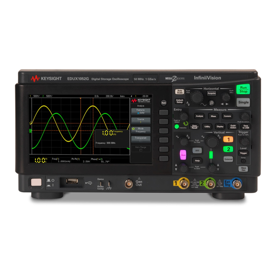
Keysight InfiniiVision 1200 X Series Manuals
Manuals and User Guides for Keysight InfiniiVision 1200 X Series. We have
2
Keysight InfiniiVision 1200 X Series manuals available for free PDF download: User Manual, Service Manual
Keysight InfiniiVision 1200 X Series User Manual (330 pages)
Brand:
Keysight
| Category:
Test Equipment
| Size: 5 MB
Table of Contents
Infiniivision 1200 X-Series and EDUX1052A/G Oscilloscopes-At a Glance
3
In this Guide
6
Table of Contents
9
1 Getting Started
21
Inspect the Package Contents
21
Power-On the Oscilloscope
22
Connect Probes to the Oscilloscope
23
Maximum Input Voltage at Analog Inputs
23
Do Not Float the Oscilloscope Chassis
23
Input a Waveform
23
Recall the Default Oscilloscope Setup
24
Use Autoscale
24
Compensate Passive Probes
25
Learn the Front Panel Controls and Connectors
26
Front Panel Overlays for Different Languages
33
Learn the Rear Panel Connectors
33
Learn the Oscilloscope Display
34
Access the Built-In Quick Help
36
Select the User Interface Language
36
2 Horizontal Controls
38
To Adjust the Horizontal (Time/DIV) Scale
38
To Adjust the Horizontal Delay (Position)
39
Panning and Zooming Single or Stopped Acquisitions
40
To Change the Horizontal Time Mode (Normal, XY, or Roll)
40
XY Time Mode
41
To Display the Zoomed Time Base
44
To Change the Horizontal Scale Knob's Coarse/Fine Adjustment Setting
45
To Position the Time Reference (Left, Center, Right)
46
3 Vertical Controls
48
To Turn Waveforms on or off (Channel or Math)
49
To Adjust the Vertical Scale
49
To Adjust the Vertical Position
49
Vertical Controls
49
To Specify Channel Coupling
50
To Specify Bandwidth Limiting
50
To Change the Vertical Scale Knob's Coarse/Fine Adjustment Setting
51
To Invert a Waveform
51
Setting Analog Channel Probe Options
51
To Specify the Channel Units
52
To Specify the Probe Attenuation
52
To Specify the Probe Skew
53
4 Analog Bus Display
57
5 FFT Spectral Analysis
57
FFT Measurement Hints
60
FFT Units
61
FFT DC Value
61
FFT Aliasing
62
FFT Spectral Leakage
63
6 Math Waveforms
66
To Display Math Waveforms
66
To Perform a Math Function on an Arithmetic Operation
67
To Adjust the Math Waveform Scale and Offset
67
Units for Math Waveforms
67
Math Operators
68
Add or Subtract
68
Multiply or Divide
69
Math Transforms
70
FFT Magnitude, FFT Phase
70
Math Filters
74
Low Pass Filter
74
7 Reference Waveforms
77
To Save a Waveform to a Reference Waveform Location
77
To Display a Reference Waveform
78
To Scale and Position Reference Waveforms
79
To Adjust Reference Waveform Skew
79
To Display Reference Waveform Information
80
To Save/Recall Reference Waveform Files To/From a USB Storage Device
80
8 Serial Bus Decode/Trigger
81
9 Display Settings
83
To Adjust Waveform Intensity
83
To Set or Clear Persistence
85
To Clear the Display
86
To Select the Grid Type
86
To Add an Annotation
87
To Adjust the Grid Intensity
87
To Freeze the Display
89
10 Labels
91
To Turn the Label Display on or off
91
To Assign a Predefined Label to a Channel
92
To Define a New Label
93
To Load a List of Labels from a Text File You Create
94
To Reset the Label Library to the Factory Default
95
11 Triggers
97
Adjusting the Trigger Level
99
Edge Trigger
99
Forcing a Trigger
99
Pulse Width Trigger
102
Pattern Trigger
104
Rise/Fall Time Trigger
106
Setup and Hold Trigger
107
Video Trigger
108
To Trigger on a Specific Line of Video
112
To Trigger on All Sync Pulses
113
To Trigger on a Specific Field of the Video Signal
114
To Trigger on All Fields of the Video Signal
115
To Trigger on Odd or Even Fields
116
Serial Trigger
118
To Select the Auto or Normal Trigger Mode
122
12 Trigger Mode/Coupling
122
To Select the Trigger Coupling
124
To Enable or Disable Trigger HF Reject
125
To Enable or Disable Trigger Noise Rejection
125
To Set the Trigger Holdoff
126
External Trigger Input
127
13 Acquisition Control
129
Running, Stopping, and Making Single Acquisitions (Run Control)
129
Overview of Sampling
130
Sampling Theory
131
Aliasing
131
Oscilloscope Bandwidth and Sample Rate
131
Oscilloscope Rise Time
133
Oscilloscope Bandwidth Required
134
Memory Depth and Sample Rate
134
Selecting the Acquisition Mode
135
Normal Acquisition Mode
136
Peak Detect Acquisition Mode
136
Averaging Acquisition Mode
138
High Resolution Acquisition Mode
140
Acquiring to Segmented Memory
141
Navigating Segments
142
Infinite Persistence with Segmented Memory
142
Segmented Memory Re-Arm Time
142
Saving Data from Segmented Memory
143
To Make Cursor Measurements
146
Cursor Examples
150
To Make Automatic Measurements
156
Measurements Summary
157
Snapshot All
159
Voltage Measurements
160
Peak-Peak
160
Maximum
160
Minimum
161
Amplitude
161
Top
161
Base
162
Overshoot
162
Preshoot
163
Average
164
DC Rms
164
Ac Rms
165
Time Measurements
167
Period
167
Frequency
168
Counter
169
Width
169
Bit Rate
169
Duty Cycle
170
Rise Time
170
Fall Time
170
Delay
170
Phase
171
At Min y
173
At Max y
173
Count Measurements
174
Positive Pulse Count
174
Negative Pulse Count
174
Rising Edge Count
175
Falling Edges Count
175
Measurement Thresholds
175
Measurement Window with Zoom Display
177
16 Mask Testing
179
To Create a Mask from a "Golden" Waveform (Automask)
179
Mask Test Setup Options
182
Mask Statistics
184
To Manually Modify a Mask File
185
Building a Mask File
188
How Is Mask Testing Done
191
17 Digital Voltmeter
193
18 Frequency Response Analysis
197
To Make Connections
197
To Set up and Run the Analysis
198
To View and Save the Analysis Results
200
19 Waveform Generator
203
To Select Generated Waveform Types and Settings
203
To Specify the Expected Output Load
206
To Add Noise to the Waveform Generator Output
207
To Use Waveform Generator Logic Presets
207
To Add Modulation to the Waveform Generator Output
208
To Set up Amplitude Modulation (AM)
209
To Set up Frequency Modulation (FM)
210
To Set up Frequency-Shift Keying Modulation (FSK)
212
To Restore Waveform Generator Defaults
213
20 Save/Recall (Setups, Screens, Data)
215
Saving Setups, Screen Images, or Data
215
To Save Setup Files
217
To Save BMP or PNG Image Files
217
To Save CSV, ASCII XY, or bin Data Files
218
Length Control
219
To Save Lister Data Files
220
To Save Reference Waveform Files to a USB Storage Device
220
To Save Masks
221
To Navigate Storage Locations
221
To Enter File Names
222
Recalling Setups, Masks, or Reference Waveforms
222
To Recall Setup Files
223
To Recall Mask Files
223
To Recall Reference Waveform Files from a USB Storage Device
224
Performing a Secure Erase
224
Recalling Default Setups
224
21 Print (Screens)
227
To Print the Oscilloscope's Display
227
To Set up Network Printer Connections
229
To Specify the Palette Option
230
To Specify the Print Options
230
I/O Interface Settings
231
Setting up the Oscilloscope's LAN Connection
232
To Establish a LAN Connection
233
Stand-Alone (Point-To-Point) Connection to a PC
234
22 Utility Settings
232
File Explorer
234
Setting Oscilloscope Preferences
236
To Choose "Expand About" Center or Ground
237
To Disable/Enable Transparent Backgrounds
237
To Load the Default Label Library
237
To Set up the Screen Saver
237
To Set Autoscale Preferences
239
Setting the Gen out Source
240
Setting the Oscilloscope's Clock
240
Enabling Remote Command Logging
241
Performing Service Tasks
243
To Perform User Calibration
243
To Perform Hardware Self Test
244
To Perform Front Panel Self Test
244
To Export Crash Log Files
244
To Display Oscilloscope Information
245
To Display the User Calibration Status
245
To Clean the Oscilloscope
245
To Check Warranty and Extended Services Status
245
To Contact Keysight
246
To Return the Instrument
246
Configuring the [Quick Action] Key
246
Utility Settings
247
Accessing the Web Interface
250
23 Web Interface
250
Control Instrument
251
Web Interface
251
Remote Front Panel
252
Remote Programming Via the Web Interface
252
Remote Programming with Keysight IO Libraries
254
Get Image
254
Save/Recall
255
Saving Files Via the Web Interface
255
Recalling Files Via the Web Interface
256
Identification Function
257
Instrument Utilities
258
Setting a Password
259
24 Reference
261
Measurement Category
261
Oscilloscope Measurement Category
261
Measurement Category Definitions
262
Maximum Input Voltages
262
Maximum Input Voltage at Analog Inputs
262
Specifications and Characteristics
261
Environmental Conditions
263
Declaration of Conformity
263
Probes and Accessories
263
Binary Data (.Bin) Format
264
Binary Data in MATLAB
265
Binary Header Format
265
Example Program for Reading Binary Data
268
Examples of Binary Files
268
Software and Firmware Updates
264
CSV and ASCII XY Files
271
CSV and ASCII XY File Structure
272
Minimum and Maximum Values in CSV Files
272
Acknowledgements
273
Product Markings and Regulatory Information
273
25 CAN Triggering and Serial Decode
275
Setup for CAN Signals
275
CAN Triggering
277
CAN Serial Decode
279
Interpreting CAN Decode
280
CAN Totalizer
281
Interpreting CAN Lister Data
282
26 I2C Triggering and Serial Decode
285
Setup for I2C Signals
285
I2C Triggering
286
I2C Serial Decode
290
Interpreting I2C Decode
291
Interpreting I2C Lister Data
292
27 LIN Triggering and Serial Decode
293
Setup for LIN Signals
293
LIN Triggering
295
LIN Serial Decode
297
Interpreting LIN Decode
299
Interpreting LIN Lister Data
300
Setup for SPI Signals
301
28 SPI Triggering and Serial Decode
301
SPI Triggering
307
SPI Serial Decode
309
Interpreting SPI Decode
311
Interpreting SPI Lister Data
312
Setup for UART/RS232 Signals
313
29 UART/RS232 Triggering and Serial Decode
313
UART/RS232 Triggering
315
UART/RS232 Serial Decode
318
Interpreting UART/RS232 Decode
320
UART/RS232 Totalizer
321
Interpreting UART/RS232 Lister Data
322
Advertisement
Keysight InfiniiVision 1200 X Series Service Manual (58 pages)
Brand:
Keysight
| Category:
Test Equipment
| Size: 1 MB
Table of Contents
In this Service Guide
3
Table of Contents
5
Figures
7
Tables
9
Characteristics and Specifications
11
Power Requirements
11
Measurement Category
12
Measurement Category Definitions
12
Maximum Input Voltages
13
Environmental Conditions
13
Specifications
14
Contact Us
14
Testing Performance
15
Overview
16
List of Test Equipment
17
Conventions
18
To Verify DC Vertical Gain Accuracy
19
Figure 1. Setting up Equipment for DC Vertical Gain Accuracy Test
22
Figure 2 Using a Blocking Capacitor to Reduce Noise
23
To Verify Bandwidth (-3 Db)
24
Figure 3 Setting up Equipment for Bandwidth (-3 Db) Verification Test
26
To Verify Time Base Accuracy
29
To Verify Trigger Sensitivity
31
Test Internal Trigger Sensitivity
32
Figure 4 Setting up Equipment for Internal Trigger Sensitivity Test
33
Keysight Infiniivision 1200 X-Series and EDUX1052A/G Oscilloscopes Performance Test Record
36
Calibrating and Adjusting
39
User Calibration
40
To Perform User Cal
40
User Cal Status
40
Troubleshooting
41
Solving General Problems with the Oscilloscope
42
If There Is no Display
42
If There Is no Trace Display
42
If the Trace Display Is Unusual or Unexpected
42
If You Cannot See a Channel
43
Verifying Basic Operation
44
To Power-On the Oscilloscope
44
To Perform Hardware Self Test
44
To Perform Front Panel Self Test
45
To Verify Default Setup
45
Figure 5 Default Setup Screen
46
To Perform an Auto Scale on the Probe Comp Signal
47
To Compensate Passive Probes
48
Figure 6 Example Pulses
48
Replacing Assemblies
49
Replaceable Parts
51
Safety Notices
53
Warnings
54
To Clean the Instrument
55
Safety Symbols
56
Advertisement
Related Products
Keysight 1000B Series
Keysight 11636A
Keysight 11683A
Keysight 16092A
Keysight 16442B
Keysight 1000A Series
Keysight 1180CZ
Keysight 16048E
Keysight 11683AZ-K01
Keysight 11683AZ-K02
Keysight Categories
Measuring Instruments
Test Equipment
Multimeter
Portable Generator
Power Supply
More Keysight Manuals
Login
Sign In
OR
Sign in with Facebook
Sign in with Google
Upload manual
Upload from disk
Upload from URL