Sign In
Upload
Manuals
Brands
Keysight Manuals
Data Loggers
AP1200A
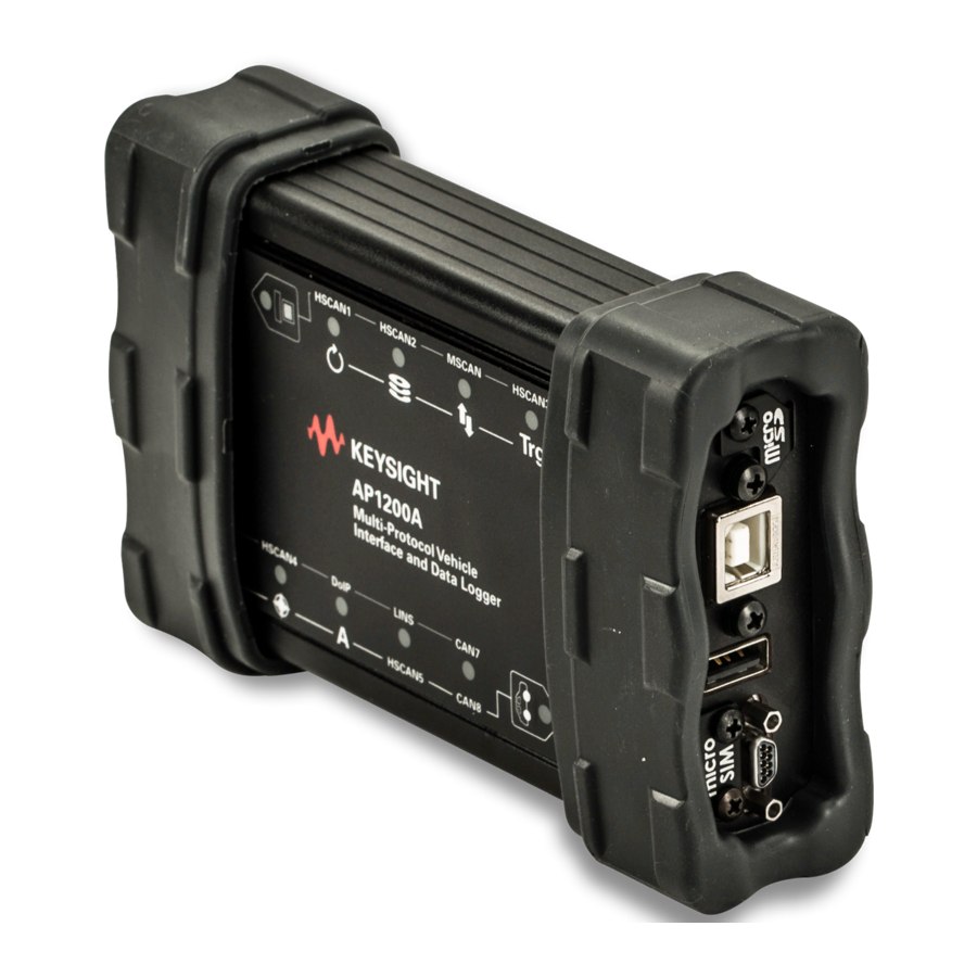
Keysight AP1200A Manuals
Manuals and User Guides for Keysight AP1200A. We have
1
Keysight AP1200A manual available for free PDF download: User Manual
Keysight AP1200A User Manual (97 pages)
Multi-Protocol Vehicle Network Interface
Brand:
Keysight
| Category:
Data Loggers
| Size: 5 MB
Table of Contents
Table of Contents
3
1 Product Inspection
12
Check the Product
12
Package Contents
13
Figure 1-1 AP1200A Package Contents
13
Visual Inspection
15
2 Introduction and Overview
18
Introduction
18
Operational Overview
19
Vehicle Network Interfacing
19
Data Acquisition and Standalone Logging
19
Simulation and Scripting
19
Summary of Key Features
20
Construction, Controls, and Cabling
20
Power and Performance
20
Network Interfaces and Features
21
Logging and Simulation
21
PC Interface and SD Card Support
22
Advanced Features
22
Hardware and Software Requirements
23
3 Hardware Overview
26
Overview
26
Case and Overall Design
27
Temperature Specification
27
Figure 3-1 AP1200A Top View
27
Figure 3-2 AP1200A Bottom View
28
Left Side Interfaces and Connectors
29
HD-26 Network Interface Connector
29
Red and Green Status Leds
29
Figure 3-3 AP1200A Left Side View
29
Right Side Interfaces and Connectors
30
USB "B" Connector
30
Μdb-9 (Micro DB-9) Connector
30
USB Host Port
30
Figure 3-4 AP1200A Right Side View
30
Microsd Slot and Cover
31
Micro-SIM Slot and Cover
31
Membrane LED Display and Keypad
32
Keypad Buttons and Leds
32
Figure 3-5 AP1200A Membrane LED Display and Keypad
32
Network/Logger Status RGB Leds
34
Figure 3-6 AP1200A Membrane LED Display and Keypad Showing Active Leds
35
Computer Set" LED Status Indicators
36
Car Set" LED Status Indicators
37
Table 3-3 Top Membrane Car Set LED Meanings
37
Standard Cables and Cable Options
38
USB "A/B" Cable
38
Figure 3-7 USB "A/B" Cable
38
Μdb-9 (Micro DB-9) to DB-9 Cable
39
Figure 3-8 Μdb-9 (Micro DB-9) to DB-9 Cable
39
Figure 3-9 Close-Up of Μdb-9 Connector
39
AP1200A-J45 Ethernet Cable Adapter
40
Figure 3-10 AP1200A Ethernet Cable Adapter
40
Figure 3-11 DB-25 Connector
40
Figure 3-12 DB-9 Connector
41
Figure 3-13 RJ-45 Socket
41
AP1200A-DB9 DB-26HD Cable F to 12X DB-9M + 1X RJ-45 + 2X Banana Plugs (for Benchtop Use)
42
Figure 3-14 DB-26HD Cable F to 12X DB-9M + 1X RJ-45 + 2X Banana Plugs
42
Optional OBD Cables
43
Figure 3-15 DB-25F to OBD-II
43
Figure 3-16 AP1200A OBD Cable with Doip Support
44
Figure 3-17 DB-26HD to OBD X2
45
4 Hardware and Software Setup
47
Overview
48
Vspy and Driver Installation and Setup
49
Hardware Connection Diagrams
50
Basic Hardware Connection Diagram
50
Figure 4-1 Basic AP1200A Hardware Connection Diagram
50
DB-25F to OBD-II (AP1200A-MUL)
51
Figure 4-2 AP1200A Hardware Connection Diagram with OBD-II
51
OBD Cable with Doip Support, HD26F to DB25M, DB9M to OBDII (AP1200A-DIP)
52
Figure 4-3 AP1200A Hardware Connection Diagram with AP1200A OBD Cable with Doip Support
52
Vehicle Network and Power Connections
53
HD-26 and OBD Cable Connections to AP1200A
53
Figure 4-4 Connecting the HD-26 Cable Connector to the
53
Figure 4-5 Attaching the DB-25 Connector of an OBD Cable to the
54
Μdb-9 to DB-9 Cable Connection to AP1200A
55
Figure 4-6 Connecting the Μdb-9 Cable Connector to the
55
PC Connection
56
Figure 4-7 Connecting the USB Cable to the AP1200A
56
5 Device Configuration Overview
58
6 Core Feature Operation Overview
60
Interfacing to Automotive Ethernet (Broadr-Reach / 100BASE-T1)
61
Figure 6-1 AP1200A Connection Diagram for Automotive Ethernet Using APM0100E Media Converter
61
7 Advanced Features
63
Overview
64
Neovi API
64
USB Host
64
8 Reference for Connector Pinouts and Cable Signal Mappings
65
Overview
66
AP1200A-J45 Connector Pinouts
67
HD-26 Connector Pinout
67
Table 8-1 AP1200A HD-26 Connector Pinout
67
Μdb-9 Connector Pinout
69
Table 8-2 AP1200A Μdb-9 Connector Pinout
69
AP1200A-J45 Ethernet Cable Adapter Connector Pinouts and Signal Mapping
70
DB-25 Connector Pinout
70
DB-9 Connector Pinout
71
Table 8-3 AP1200A Ethernet Cable Adapter DB-25 Connector
71
Table 8-4 AP1200A Ethernet Cable Adapter DB-9 Connector
71
RJ-45 Connector Pinout
72
Table 8-5 AP1200A Ethernet Cable Adapter RJ-45 Connector
72
Cable Signal Mapping
73
AP1200A-DB9 DB-26HD Cable F to 12X DB-9M + 1X RJ-45 + 2X Banana Plugs (for Benchtop Use)
75
HS CAN, MS CAN and Switchable SW CAN
75
Lin
76
Table 8-8 LIN
76
Banana Jacks
77
AP1200A-MUL DB-25F to OBD-II Cable Connector Pinouts and Signal Mapping
78
DB-25 Connector Pinout
78
Table 8-11 DB-25 Connector Pinout
78
OBD-II / J1962 Connector Pinout
79
Cable Signal Mapping
80
Table 8-12 OBD-II / J1962 Connector Pinout
80
Table 8-13 AP1200A-MUL Cable Signal Mapping
80
AP1200A-DIP OBD Cable with Doip Support, HD26F to DB25M, DB9M to OBDII Cable Connector Pinouts and Signal Mapping
82
DB-25 Connector Pinout
82
DB-9 Connector Pinout
83
OBD-II / J1962 Connector Pinout
84
Cable Signal Mapping
85
Table 8-17 AP1200A OBD Cable with Doip Support Signal Mapping
86
Table 8-18 AP1200A-GMB OBD Cable OBD X2
88
Table A-1 Abbreviation and Definition
91
Advertisement
Advertisement
Related Products
Keysight APM0100E
Keysight APS-M8400
Keysight APS-ONE-100
Keysight APS-M1010
Keysight APM1000ET
Keysight AP5041A G3
Keysight AP5042A G3
Keysight Agilent X-Series
Keysight AC6801A
Keysight AC6802B
Keysight Categories
Measuring Instruments
Test Equipment
Multimeter
Portable Generator
Power Supply
More Keysight Manuals
Login
Sign In
OR
Sign in with Facebook
Sign in with Google
Upload manual
Upload from disk
Upload from URL