Table of Contents
Advertisement
Quick Links
Advertisement
Table of Contents

Related Manuals for Keysight AP1200A


Summary of Contents for Keysight AP1200A
- Page 1 Keysight AP1200A Multi-Protocol Vehicle Network Interface User Guide...
- Page 2 FAR 27.401 or DFAR could result in personal injury or death. 227.7103-5 (c), as applicable in any Do not proceed beyond a WARNING technical data. notice until the indicated conditions are fully understood and met. Keysight AP1200A Multi-Protocol Vehicle Network Interface User Guide...
-
Page 3: Table Of Contents
......... .30 Keysight AP1200A Multi-Protocol Vehicle Network Interface User Guide... - Page 4 ..... . . 40 AP1200A-DB9 DB-26HD cable F to 12x DB-9M + 1x RJ-45 + 2x Banana Plugs (for benchtop use) .
- Page 5 ........73 AP1200A-DB9 DB-26HD cable F to 12x DB-9M + 1x RJ-45 + 2x Banana Plugs (for benchtop use) .
- Page 6 ........94 Keysight AP1200A Multi-Protocol Vehicle Network Interface User Guide...
- Page 7 ..32 Figure 3-6 AP1200A Membrane LED Display and Keypad Showing Active LEDs .......35 Figure 3-7 USB “A/B”...
- Page 8 Figure 8-1 AP1200A HD-26 Connector Pin Numbering ..68 Figure 8-2 AP1200A µDB-9 Connector Pin Numbering ..69 Keysight AP1200A Multi-Protocol Vehicle Network Interface User Guide...
- Page 9 ........83 Table 8-16 AP1200A OBD Cable with DoIP Support OBD-II / J1962 Connector Pinout .
- Page 10 THIS PAGE HAS BEEN INTENTIONALLY LEFT BLANK. Keysight AP1200A Multi-Protocol Vehicle Network Interface User Guide...
- Page 11 Keysight AP1200A Multi-Protocol Vehicle Network Interface User Guide Product Inspection Check the Product...
-
Page 12: Product Inspection
Product Inspection Check the Product Upon receiving the AP1200A Multi-Protocol Vehicle Network Interface from Keysight Technologies, perform the following product inspection: – Inspect the outer shipping container, foam-lined instrument case, and product for damage. – Retain the outer cardboard shipping container until you have inspected the contents of the shipment for completeness, and you have checked the product mechanically and electrically. -
Page 13: Package Contents
Product Inspection Package Contents Standard Items: AP1200A 32 GB Micro SD Card DB-9F to DB-9M USB 2.0 (A/B) Cable Cable Adapter AP1200A-J45 AP1200A-DB9 Optional Items: AP1200A-DIP AP1200A-MUL AP1200A-GMP Figure 1-1 AP1200A Package Contents Keysight AP1200A Multi-Protocol Vehicle Network Interface User Guide... - Page 14 – One µDB-9F to DB-9M Cable Adapter – AP1200A-J45 Ethernet adapter cable, DB-26F- DB-25M, DB9(M)- RJ-45 – AP1200A-DB9 DB-26HD cable F to 12x DB-9M + 1x RJ-45 + 2x Banana Plugs (for benchtop use) You will also receive a “Startup Guide” card to help you get going quickly with your device.
-
Page 15: Visual Inspection
AP00000A-SPY Vehicle Spy or use a limited Vehicle Spy Trial, available from Keysight's partner, Intrepid Control Systems here. It is also possible to control the AP1200A from within other software using one of the APIs that the device supports Visual Inspection Be sure to inspect all instrument cables, Ethernet cables, and devices carefully before making a connection. - Page 16 Product Inspection THIS PAGE HAS BEEN INTENTIONALLY LEFT BLANK. Keysight AP1200A Multi-Protocol Vehicle Network Interface User Guide...
- Page 17 Keysight AP1200A Multi-Protocol Vehicle Network Interface User Guide Introduction and Overview Introduction Operational Overview Summary of Key Features Hardware and Software Requirements...
-
Page 18: Introduction And Overview
Introduction The AP1200A is a general-purpose interface tool, providing access to multiple channels of CAN, LIN, and other vehicle networks. The AP1200A can be used for standalone logging based on precise specifications, to monitor and transmit on networks, and create custom simulations for network analysis and troubleshooting. -
Page 19: Operational Overview
USB without the need to remove the card. Simulation and Scripting The AP1200A not only allows you to receive data from vehicle networks but also to transmit on them. Using VSpy or other software, you can define transmit messages with custom data and send them manually or on a schedule of your choosing. -
Page 20: Summary Of Key Features
With the AP1200A, Keysight fits a lot of power and functionality into a tough little package. To give you an idea of how much you can do with the AP1200A, the following details a summary of the device's most important design, construction, operational, and performance features. -
Page 21: Network Interfaces And Features
USB power – Low power consumption Network Interfaces and Features The following details the network interfaces and features of the AP1200A: – 6 dedicated DW CAN channels (ISO 11898-2): 5 Dual Wire HS CAN, 1 Dual Wire MS CAN –... -
Page 22: Pc Interface And Sd Card Support
PC Interface and SD Card Support The following details the PC interface and SD card support of the AP1200A: – High-speed isolated USB connection protects the PC from potential damage – Support for microSD cards up to 128 GB in size –... -
Page 23: Hardware And Software Requirements
The setup program for VSpy will also install the necessary drivers for your AP1200A. If you do not have a VSpy license, you can use the VSpy trial version for basic network interfacing and driver setup. - Page 24 Introduction and Overview THIS PAGE HAS BEEN INTENTIONALLY LEFT BLANK. Keysight AP1200A Multi-Protocol Vehicle Network Interface User Guide...
- Page 25 Keysight AP1200A Multi-Protocol Vehicle Network Interface User Guide Hardware Overview Overview Case and Overall Design Left Side Interfaces and Connectors Right Side Interfaces and Connectors Membrane LED Display and Keypad Standard Cables and Cable Options...
-
Page 26: Hardware Overview
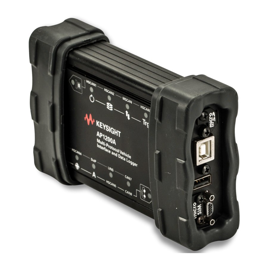
Hardware Overview Overview The design of the AP1200A is with all of its connectors located on its sides, making the device easier to use in cramped quarters. There is the left side and right side of the unit, as oriented when facing the device with its top label text. -
Page 27: Case And Overall Design
Keysight recommends that you leave them in place. Figure 3-1 AP1200A Top View Temperature Specification The AP1200A is operational in a temperature range from -5 °C to 60 °C. Keysight AP1200A Multi-Protocol Vehicle Network Interface User Guide... -
Page 28: Figure 3-2 Ap1200A Bottom View
Hardware Overview The bottom of the AP1200A contains useful reference information, including the device serial number, pinouts of its HD-26, and µDB-9 connectors, as shown in Figure 3-2. Pinouts for all AP1200A connectors and cables are in Chapter 8, "Reference for Connector Pinouts and Cable Signal Mappings". -
Page 29: Left Side Interfaces And Connectors
Red and Green Status LEDs You can determine the status of the AP1200A by observing the blink pattern of these two LEDs. The patterns here will be identical to those seen in the keypad button LEDs on the top membrane panel detailed in “Membrane LED Display and... -
Page 30: Right Side Interfaces And Connectors
DB-9 commonly used in the automotive industry. USB Host Port The USB “A” connector allows the AP1200A to act as a USB host so that other devices can plug into it. Refer to “USB Host”... -
Page 31: Microsd Slot And Cover
Slot and Cover This slot holds the microSD card that stores data logged or captured by the AP1200A. It is protected by a metal cover that prevents accidental ejection of the card and protects the slot from dirt and debris. -
Page 32: Membrane Led Display And Keypad
AP1200A. Keypad Buttons and LEDs There are two keypad buttons on the AP1200A’s top membrane as follows: – One with a white computer icon located near the top left – One with a white car icon located near the bottom right... - Page 33 3-6. – Car Icon Button (Bottom Right): When pressed, it activates the “car set” of LED meanings: each RGB LED shows information about a network or AP1200A function based on the white icon or label below it. The buttons themselves also contain red and green LEDs, which flash in the same pattern as the red and green LEDs on the left side of the device see “Left Side...
-
Page 34: Network/Logger Status Rgb Leds
– Green+Blue+Red (White): The device is transmitting, receiving, and detecting errors on this channel. Figure 3-6 shows the top membrane of the AP1200A in active use, with the computer set of status indicators active, meaning that transmissions are occurring on five channels and errors on one. -
Page 35: Figure 3-6 Ap1200A Membrane Led Display And Keypad Showing Active Leds
The other LEDs thus mean that the AP1200A is active and transmitting on the HSCAN1, HSCAN2, MSCAN, HSCAN3, and HSCAN4 channels (in use all these flash a few times per second.) The LED for HSCAN4 is yellowish;... -
Page 36: Computer Set" Led Status Indicators
“Computer Set” LED Status Indicators Table 3-2 lists the computer labels on the AP1200A membrane interface and describes the meaning of the LED associated with each when the computer set is selected (top left keypad button flashing). The LEDs are listed from top to bottom, left to right, as seen looking at the membrane in its usual orientation. -
Page 37: Car Set" Led Status Indicators
“Car Set” LED Status Indicators Table 3-3 lists the car labels/icons on the AP1200A membrane interface and describes the meaning of the LEDs for each when the car set is selected (bottom right keypad button flashing). Again the LEDs are listed from top to bottom, left to right. -
Page 38: Standard Cables And Cable Options
PCs or other hosts to USB devices that do not have integrated cables. The detachable cable makes the AP1200A easier to transport compared to a built-in cable. You can easily replace the cable if it is ever damaged. Figure 3-7 USB “A/B”... -
Page 39: Μdb-9 (Micro Db-9) To Db-9 Cable
Hardware Overview µDB-9 (Micro DB-9) to DB-9 Cable The µDB-9 connector allows the AP1200A to be more compact. This is a "straight-through" cable that converts the smaller connector to the regular DB-9 used in automotive applications. The cable is as shown in... -
Page 40: Ap1200A-J45 Ethernet Cable Adapter
Hardware Overview AP1200A-J45 Ethernet Cable Adapter This special cable splits the HD-26 connector on the left side of the AP1200A to three connectors used to communicate with vehicle networks. This cable allows the AP1200A to connect to vehicle networks and receive its primary power input. -
Page 41: Figure 3-12 Db-9 Connector
Ethernet cable for Automotive Ethernet and DoIP applications. Figure 3-13 RJ-45 Socket For details on pinouts, see “AP1200A-J45 Ethernet Cable Adapter Connector Pinouts and Signal Mapping” on page 70. Keysight AP1200A Multi-Protocol Vehicle Network Interface User Guide... -
Page 42: Ap1200A-Db9 Db-26Hd Cable F To 12X Db-9M + 1X Rj-45 + 2X Banana Plugs (For Benchtop Use)
Hardware Overview AP1200A-DB9 DB-26HD cable F to 12x DB-9M + 1x RJ-45 + 2x Banana Plugs (for benchtop use) This cable breaks out the DB-26HD Female connector on the AP1200A to individual DB-9M connectors for multiple 8 x CAN and 4 x LIN channels, plus an additional RJ-45 connector for DoIP and two banana plugs for power. -
Page 43: Optional Obd Cables
The AP1200A comes optionally with OBD cables, which interface the device to a vehicle or bench OBD port. “Hardware Connection Diagrams” on page 50 for connection diagrams that show how to connect the cables to the AP1200A and your network or bench. AP1200A-MUL DB-25F to OBD-II This cable in Figure 3-15 has a standard black OBD-II connector and is suitable for use with the vehicles of most OEMs. -
Page 44: Figure 3-16 Ap1200A Obd Cable With Doip Support
Hardware Overview AP1200A-DIP OBD Cable with DoIP support, HD26Fto DB25M, DB9M to OBDII This special cable attaches to the AP1200A's HD-26 connector in place of the regular AP1200A Ethernet Cable Adapter. Figure 3-16 shows the DB-25, DB-9, and OBD-II connectors wired for use with DoIP. Suitable for gatewaying all traffic over pins 6 and 14 exclusively, or for use with DoIP. -
Page 45: Figure 3-17 Db-26Hd To Obd X2
Hardware Overview AP1200A-GMB DB-26HD to OBD x2 This cable adapts the AP1200A to two of the following SAE J1962 connectors: – One for the DLC on Global B vehicles – One for a proprietary harness Figure 3-17 DB-26HD to OBD x2 For details on pinouts, see “AP1200A-GMB DB-26HD to OBD x2”... - Page 46 Hardware Overview THIS PAGE HAS BEEN INTENTIONALLY LEFT BLANK. Keysight AP1200A Multi-Protocol Vehicle Network Interface User Guide...
-
Page 47: Hardware And Software Setup
Keysight AP1200A Multi-Protocol Vehicle Network Interface User Guide Hardware and Software Setup Overview VSpy and Driver Installation and Setup Hardware Connection Diagrams Vehicle Network and Power Connections PC Connection... -
Page 48: Overview
Hardware and Software Setup Overview This chapter details the steps necessary to set up the AP1200A to work with a vehicle network. Steps provided include how to install the required software and drivers, connect cables between the AP1200A and the network, and link the unit to a PC. -
Page 49: Vspy And Driver Installation And Setup
Keysight recommends the full-licensed version of VSpy so that you get the most from your AP1200A. You can get the limited trial version of VSpy with the installer available here. -
Page 50: Hardware Connection Diagrams
Basic Hardware Connection Diagram Figure 4-1 shows the basic hardware configuration of the AP1200A, with the USB cable connecting the device to the PC, and the AP1200A Ethernet Cable Adapter and µDB-9 to DB-9 cables linking it to vehicle networks. DB-25 AP1200A USB “A/B”... -
Page 51: Db-25F To Obd-Ii (Ap1200A-Mul)
DB-25F to OBD-II (AP1200A-MUL). OBD-II (AP1200A-MUL) Cable USB “A/B” AP1200A DB-25 Cable Vehicle Networks DB-9 HD-26 µDB-9 (Micro DB-9) RJ-45 DB-9 Figure 4-2 AP1200A Hardware Connection Diagram with OBD-II (AP1200A-MUL) Cable Keysight AP1200A Multi-Protocol Vehicle Network Interface User Guide... -
Page 52: Obd Cable With Doip Support, Hd26F To Db25M, Db9M To Obdii (Ap1200A-Dip)
OBD Cable with DoIP support, HD26F to DB25M, DB9M to OBDII (AP1200A-DIP) Figure 4-3 shows the special OBD Cable with DoIP support, HD26F to DB25M, DB9M to OBDII (AP1200A-DIP) that replaces the AP1200A Ethernet Cable Adapter. DB-25 AP1200A USB “A/B” Cable... -
Page 53: Vehicle Network And Power Connections
The two connectors on the AP1200A attach the device to vehicle networks. The HD-26 connector on the left side of the device provides primary power input to the AP1200A and also carries most of the network channels. The OBD cable is attached to the HD-26 connector, either directly or indirectly. The µDB-9 connector on the right side of the device carries LIN and miscellaneous I/O channels, which you may or may not need depending on your application. -
Page 54: Figure 4-5 Attaching The Db-25 Connector Of An Obd Cable To The
As soon as you connect the device supplying power to the cable attached to the AP1200A, the device should boot up. You will recognize this by green LEDs beginning to flash in a quick and regular pattern on both the side of the device next to the HD-26 connection and in the upper left corner of the top membrane interface. -
Page 55: Μdb-9 To Db-9 Cable Connection To Ap1200A
Hardware and Software Setup µDB-9 to DB-9 Cable Connection to AP1200A Continue with the µDB-9 connector on the right side of the AP1200A, using the special µDB-9 to DB-9 cable that comes with the device. This connection carries LIN and miscellaneous I/O channels for networks that require them; if they are not relevant to you, skip the following steps. -
Page 56: Pc Connection
USB 2.0 (or higher) port on the computer, or indirectly through a USB hub. The AP1200A can draw up to the USB standard maximum of 500 mA through its USB connection. All computers should be able to supply this amount of current. - Page 57 Keysight AP1200A Multi-Protocol Vehicle Network Interface User Guide Device Configuration Overview...
-
Page 58: Device Configuration Overview
Device Configuration Overview The AP1200A ships from the factory ready to use with its default settings. However, you can also customize its operation to your exact needs by adjusting dozens of parameters that control its internal hardware and firmware. In this... - Page 59 Keysight AP1200A Multi-Protocol Vehicle Network Interface User Guide Core Feature Operation Overview Interfacing to Automotive Ethernet (BroadR-Reach / 100BASE-T1)
-
Page 60: Core Feature Operation Overview
Core Feature Operation Overview Now that we have completed installing and configuring our hardware and software, we are ready to use the AP1200A. This chapter details some of the many applications of the AP1200A. Refer to “Core Feature Operation” here... -
Page 61: Interfacing To Automotive Ethernet (Broadr-Reach / 100Base-T1)
Ethernet cable. Then, connect the BroadR-Reach ECU or network to the APM0100E's Molex Mini50 connector on the other side of the converter. Power provided for the APM0100E is via the USB host slot on the AP1200A. This feature allows the AP1200A to power the APM0100E on or off as needed. - Page 62 Core Feature Operation THIS PAGE HAS BEEN INTENTIONALLY LEFT BLANK. Keysight AP1200A Multi-Protocol Vehicle Network Interface User Guide...
-
Page 63: Advanced Features
Keysight AP1200A Multi-Protocol Vehicle Network Interface User Guide Advanced Features Overview neoVI API USB Host... -
Page 64: Overview
The chapter provides additional information on some of the AP1200A's new and advanced features. neoVI API The AP1200A comes with support for a full API that allows you to control the device from other software packages or custom-written software. For instructions on using the API, consult the documentation here. -
Page 65: Reference For Connector Pinouts And Cable Signal Mappings
Overview AP1200A-J45 Connector Pinouts AP1200A-J45 Ethernet Cable Adapter Connector Pinouts and Signal Mapping AP1200A-DB9 DB-26HD cable F to 12x DB-9M + 1x RJ-45 + 2x Banana Plugs (for benchtop use) AP1200A-MUL DB-25F to OBD-II Cable Connector Pinouts and Signal Mapping... -
Page 66: Overview
Overview This chapter contains the complete information on pinouts for the connectors and the network interface cables on the AP1200A. Provided are the following tables that show the mappings of signals between the pin numbers on the connectors of each network cable. -
Page 67: Ap1200A-J45 Connector Pinouts
Reference for Connector Pinouts and Cable Signal Mappings AP1200A-J45 Connector Pinouts The following details the pinouts for the connectors on the AP1200A. HD-26 Connector Pinout Table 8-1 lists the pin assignments for the HD-26 connector, with pin numbering for the connector, as shown in Figure 8-1. - Page 68 HS CAN 7 H / LSFT CAN 2 H / SW CAN Low Speed Fault Tolerant CAN channel 2, high / Single Wire CAN channel 1 Figure 8-1 AP1200A HD-26 Connector Pin Numbering Keysight AP1200A Multi-Protocol Vehicle Network Interface User Guide...
-
Page 69: Μdb-9 Connector Pinout
Enhanced miscellaneous I/O channel 1 (analog or digital with PWM and 0-40 V EMISC 1 support) Enhanced miscellaneous I/O channel 2 (analog or digital with PWM and 0-40 V EMISC 2 support) Figure 8-2 AP1200A µDB-9 Connector Pin Numbering Keysight AP1200A Multi-Protocol Vehicle Network Interface User Guide... -
Page 70: Ap1200A-J45 Ethernet Cable Adapter Connector Pinouts And Signal Mapping
AP1200A-J45 Ethernet Cable Adapter Connector Pinouts and Signal Mapping The primary cable for connecting the AP1200A to vehicle networks has four connectors: HD- 26, DB-25, DB-9, and RJ-45. The HD-26 connector mates to the HD-26 on the AP1200A and uses the same pinout as shown in Table 8-1;... -
Page 71: Db-9 Connector Pinout
DB-9 connector on this cable. Table 8-4 AP1200A Ethernet Cable Adapter DB-9 Connector Pinout Name Description Number LIN 1 LIN channel 1 LIN 2 LIN channel 2 Keysight AP1200A Multi-Protocol Vehicle Network Interface User Guide... -
Page 72: Rj-45 Connector Pinout
ETH TX+ Ethernet transmit channel, positive ETH TX- Ethernet transmit channel, negative ETH RX+ Ethernet receive channel, positive No connection No connection ETH RX- Ethernet receive channel, negative No connection No connection Keysight AP1200A Multi-Protocol Vehicle Network Interface User Guide... -
Page 73: Cable Signal Mapping
Reference for Connector Pinouts and Cable Signal Mappings Cable Signal Mapping Table 8-6 shows the mapping of signals for the AP1200A Ethernet Cable Adapter, by pin order on the HD-26 that connects to the AP1200A. Table 8-6 AP1200A Ethernet Cable Adapter Signal Mapping... - Page 74 HS CAN 7 H / High Speed CAN channel 7, high / LSFT CAN 2 H / Low Speed Fault Tolerant CAN channel 2, high / SW CAN Single Wire CAN channel 1 Keysight AP1200A Multi-Protocol Vehicle Network Interface User Guide...
-
Page 75: Ap1200A-Db9 Db-26Hd Cable F To 12X Db-9M + 1X Rj-45 + 2X Banana Plugs (For Benchtop Use)
AP1200A-DB9 DB-26HD cable F to 12x DB-9M + 1x RJ-45 + 2x Banana Plugs (for benchtop use) This cable breaks out the DB-26HD Female connector on the AP1200A VNET to individual DB-9M connectors for multiple CAN and LIN channels, plus an additional RJ-45 connector for DoIP and two banana plugs for power. -
Page 76: Lin
Table 8-8 HD-26F DB-9M Signal DB-9M Signal Description LIN Data GND/PWR Pin Number LIN 1 LIN channel 1 LIN 2 LIN channel 2 LIN 3 LIN channel 3 LIN 4 LIN channel 4 Keysight AP1200A Multi-Protocol Vehicle Network Interface User Guide... -
Page 77: Banana Jacks
Ethernet receive channel, positive ETH RX - Ethernet receive channel, negative Banana Jacks Table 8-10 shows the connector pinouts and plugs for banana jacks. Table 8-10 Banana Jacks HD-26F Pin Number Plugs PWR+ GND- Keysight AP1200A Multi-Protocol Vehicle Network Interface User Guide... -
Page 78: Ap1200A-Mul Db-25F To Obd-Ii Cable Connector Pinouts And Signal Mapping
Reference for Connector Pinouts and Cable Signal Mappings AP1200A-MUL DB-25F to OBD-II Cable Connector Pinouts and Signal Mapping These two cables have the same pinouts and signal mappings, as they differ only in the physical construction of the OBD-II connector. -
Page 79: Obd-Ii / J1962 Connector Pinout
Chassis Ground Signal GND Signal Ground CAN H High Speed CAN channel, high ISO9141/K ISO 9141-2 K-Line Discretionary Discretionary Discretionary Discretionary J1850 - J1850 line, negative Discretionary Discretionary Discretionary Discretionary Discretionary Discretionary Keysight AP1200A Multi-Protocol Vehicle Network Interface User Guide... -
Page 80: Cable Signal Mapping
AP1200A. Cable Signal Mapping Table 8-13 shows the mapping of signals for the AP1200A-MUL. The signal names for both connectors are shown and the table is based on the OBD-II connector's pin order. Table 8-13... - Page 81 Table 8-13 AP1200A-MUL Cable Signal Mapping OBD-II Pin Number OBD-II Signal DB-25 Signal DB-25 Pin Number Discretionary HS CAN 2 L CAN L HS CAN 1 L ISO L ISO L VBATT VBATT Keysight AP1200A Multi-Protocol Vehicle Network Interface User Guide...
-
Page 82: Ap1200A-Dip Obd Cable With Doip Support, Hd26F To Db25M, Db9M To Obdii Cable Connector Pinouts And Signal Mapping
This special OBD cable replaces the AP1200A Ethernet Cable Adapter and contains HD-26, DB- 25, DB-9 and OBD-II connectors. The HD-26 connector mates to the HD-26 on the AP1200A and uses the same pinout shown in Table 8-1; the other connectors are described as follows, along with a signal mapping table. -
Page 83: Db-9 Connector Pinout
V BATT DC Input Power DB-9 Connector Pinout Table 8-15 contains the pinout for the DB-9 connector on this cable. Table 8-15 AP1200A OBD Cable with DoIP Support DB-9 Connector Pinout Pin Number Name Description LIN 1 LIN channel 1... -
Page 84: Obd-Ii / J1962 Connector Pinout
Reference for Connector Pinouts and Cable Signal Mappings Table 8-15 AP1200A OBD Cable with DoIP Support DB-9 Connector Pinout Pin Number Name Description No connection No connection No connection No connection OBD-II / J1962 Connector Pinout Table 8-16 shows the pinout for the OBD-II / J1962 connector on the cable. -
Page 85: Cable Signal Mapping
Cable Signal Mapping Table 8-17 shows the mapping of signals for the AP1200A OBD Cable with DoIP Support, ordered by pin number on the HD-26 that connects to the AP1200A. Table 8-17 AP1200A OBD Cable with DoIP Support Signal Mapping HD-26 ... -
Page 86: Table 8-17 Ap1200A Obd Cable With Doip Support Signal Mapping
Reference for Connector Pinouts and Cable Signal Mappings Table 8-17 AP1200A OBD Cable with DoIP Support Signal Mapping HD-26 DB-25 DB-9 OBD-II Signal Name Signal Description Pin Number Pin Number Pin Number Pin Number HS CAN 2 H High Speed CAN channel 2, high... - Page 87 Reference for Connector Pinouts and Cable Signal Mappings AP1200A-GMB DB-26HD to OBD x2 The following lists the pinout for DB-26HD to OBD x2 (AP1200A-GMB) cable. OBD Cable OBD x2 (AP1200A-GMB) Table 8-18 lists the pinout for DB-26HD to OBD x2 (AP1200A-GMB) cable.
-
Page 88: Table 8-18 Ap1200A-Gmb Obd Cable Obd X2
HS CAN 7 H / High Speed CAN channel 7, high / LSFT CAN 2 H / Low Speed Fault Tolerant CAN channel 2, high / SW CAN 1 Single Wire CAN channel 1 Keysight AP1200A Multi-Protocol Vehicle Network Interface User Guide... - Page 89 Keysight AP1200A Multi-Protocol Vehicle Network Interface User Guide Appendix List of Abbreviations...
- Page 90 Low-Speed Fault-Tolerant CAN Microphone MISC Miscellaneous MS CAN Medium Speed Controller Area Network OBD-II On-board Diagnostics Original Equipment Manufacturer Pulse with Modulation SMSC LAN9500 Hi Speed USB 2.0 to 10/100 Ethernet Controller Keysight AP1200A Multi-Protocol Vehicle Network Interface User Guide...
-
Page 91: Table A-1 Abbreviation And Definition
Appendix Table A-1 Abbreviation and Definition Abbreviation Definition SW CAN Single Wire Controller Area Network Intrepid Control Systems Driver VSpy Vehicle Spy Measurement and Calibration Protocol Keysight AP1200A Multi-Protocol Vehicle Network Interface User Guide... - Page 92 Appendix THIS PAGE HAS BEEN INTENTIONALLY LEFT BLANK. Keysight AP1200A Multi-Protocol Vehicle Network Interface User Guide...
- Page 93 Keysight AP1200A Multi-Protocol Vehicle Network Interface User Guide Appendix Service and Support...
- Page 94 800 810 0189 0120 (421) 345 1 800 375 8100 Hong Kong Korea Taiwan 800 938 693 080 769 0800 0800 047 866 Other Asian Countries: (65) 6375 8100 www.keysight.com/find/contactus Keysight AP1200A Multi-Protocol Vehicle Network Interface User Guide...
- Page 95 Switzerland 0805 980 333 0800 80 53 53 +32 800 58580 *0.125 €/minute United Kingdom Netherlands Germany 0800 0260 637 0800 0233 200 0800 6270 999 Other Unlisted Countries: www.keysight.com/find/contactus Keysight AP1200A Multi-Protocol Vehicle Network Interface User Guide...
- Page 96 Appendix THIS PAGE HAS BEEN INTENTIONALLY LEFT BLANK. Keysight AP1200A Multi-Protocol Vehicle Network Interface User Guide...
- Page 97 This information is subject to change without notice. Always refer to the English version at the Keysight website for the latest revision. © Keysight Technologies 2020 September 2020 www.keysight.com...
Need help?
Do you have a question about the AP1200A and is the answer not in the manual?
Questions and answers